Enhanced transmission through sub-wavelength apertures by using
metamaterials
Chapter · January 2011 DOI: 10.1142/9789814355193_0016 CITATIONS 0 READS 51 7 authors, including:Some of the authors of this publication are also working on these related projects: MetasurfacesView project
Sharp Bends in waveguideView project Filiberto Bilotti
Università Degli Studi Roma Tre 314 PUBLICATIONS 3,613 CITATIONS SEE PROFILE Luca Scorrano Elettronica S.p.A. 29 PUBLICATIONS 87 CITATIONS SEE PROFILE
Kamil Boratay Alici
TUBITAK Space Technologies Research Institute 48 PUBLICATIONS 1,479 CITATIONS SEE PROFILE Koray Aydin Northwestern University 131 PUBLICATIONS 5,880 CITATIONS SEE PROFILE
All content following this page was uploaded by Koray Aydin on 29 March 2017.
1
ENHANCED TRANSMISSION THROUGH SUB-WAVELENGTH APERTURES BY USING METAMATERIALS
Filiberto Bilotti1, Luca Scorrano1, Kamil B. Alici2, Koray Aydin3, Ozgur A. Cakmak2, Ekmel Ozbay2, and Lucio Vegni1
1Department of Applied Electronics, University ROMA TRE Via della Vasca Navale, 84 I-00146 Rome, Italy
E-mail: [email protected] 2
Nanotechnology Research Centre, Bilkent University 06800 Bilkent-Ankara, Turkey
3 Thomas J. Watson Laboratories of Applied Physics, California Institute of Technology, Pasadena, CA, USA
In this Chapter, the role of complex artificial structures in enhancing the power transmission through sub-wavelength apertures is discussed. Such devices are aimed at exciting highly localized resonances in order to increase the aperture equivalent magnetic and electric dipole moments. Some examples, based on epsilon-near-zero metamaterials (ENZ), frequency selective surfaces (FSSs) and split-ring resonators (SRRs) at microwaves, and silver nano-particle pairs at terahertz scale, are presented. Such structures may find applications in different fields, such as high-resolution spatial filters, ultra-diffractive imaging systems, high-capacity optical memories, enhanced light throughput tips for nears-field scanning optical microscopes, etc.
1. Introduction
Power transmission through an electrically small aperture in a flat, indefinite, perfect conducting screen with negligible thickness has been deeply investigated since 40s by Bethe [1]. According to Bethe’s theory, if the aperture is sub-wavelength, the ratio of the transmitted power to
the whole incident power on the hole (T0 ) is extremely small and it
results proportional to the fourth power of the linear electrical dimension of the aperture: 2 0 ∼ a T λ (1)
being T0 the power transmission, a the linear geometrical dimension of
the aperture and λ the wavelength of the impinging radiation. This result is achieved by neglecting the retardation effects due to the finite thickness of the screen and the higher-order multi-pole moments. In this case, the transmission can be modelled as due to both an equivalent magnetic dipole moment pm parallel to the screen and an equivalent electric dipole moment pe normal to the screen, respectively, given by:
3 0 3 0 ( / 3 ) (2 / 3 ) = − = − e m p a E p a H π π (2)
being E0,H0 the amplitudes of the normal electric and the tangential magnetic fields at the aperture.
Other models have been developed to generalize Bethe’s result that has been proven to be valid only for radii smaller than 0.2 λ (see [2]). In [3], for instance, a uniform field model has been developed, assuming a constant magnetic current density in the hole and deriving analytical expressions for the normalized cross section (which is defined as the ratio of the total transmitted power to the total incident power over the aperture area) also for the case a>0.2λ. However, assuming to be in the limit a≪λ, expression (2) are fully verified and, in principle, it can be assumed that, in order to enhance the power transmission, it is enough to increase pe,pm.
Power transmission enhancement through electrically small apertures, has recently received a growing interest by the scientific community due to the successful experimental demonstration at optical frequencies by Ebbesen’s group in 1999 [3], successively explained in terms of the excitation of leaky modes by Oliner, Jackson and their co-workers in 2003 [4]. This phenomenon has been widely studied by using both sub-wavelength periodic hole arrays [6-9] and structures with a single aperture [10-16] and many different approaches have been proposed such
as corrugating the metal surface with periodic grooves [9], filling the hole with a material of high dielectric permittivity [10,11], using different aperture shapes [12,13] or by placing artificially designed metamaterial covers in front of the aperture [14-16].
In this Chapter we review our recent efforts to design proper metamaterial structures aimed at enhancing the transmission through single sub-wavelength apertures at both microwave and optical frequencies.
2. Power transmission enhancement through small apertures: the metamaterial-based approach
To the authors’ best knowledge, the first theoretical setup based on metamaterials (MTMs) scaling down to microwave frequencies the phenomenon of the extraordinary transmission (also known as EOT, Extraordinary Optical Transmission) has been presented in [14], relying, on the excitation of superficial leaky modes. The idea was to cover the entrance face of a metallic screen by a slab having an extremely low relative permittivity (ENZ medium) or permeability (MNZ medium), depending on the polarization of the incident field (TM or TE, respectively). By reciprocity, an identical slab is placed on the exit face. In [14] it is demonstrated that the slab, provided that its thickness is wisely chosen, may support leaky-modes which are able to couple energy from the field impinging on the structure and enhance the transmission through the aperture.
However, the leaky modes that have to be excited turn out to be highly directive modes, characterized by a small valued imaginary part of the wave-number. This implies on one hand the need of materials with extreme-valued constitutive parameters [17] and, on the other hand, the large dimensions of the cover (in terms of both thickness and transverse size), limiting, thus, the range of possible practical applications.
The structures reviewed in the following Sections are aimed at reducing both the overall size of the cover and the complexity of the equivalent real-life structures, through to the use of different physical phenomena.
3. Design of real-life structures at microwaves: FSS-based devices
In order to design a complex surface suitable for a practical implementation and capable to enhance both the tangential magnetic on the hole, a possible strategy is to use frequency selective surfaces (FSS) [18], which have been proven to be a valid alternative to bulk MTMs in many practical cases [19].
z=0 0,k0 η η0, k0 z= −d FSS1 Z Γ
Fig. 1. Sketch of an FSS-based setup (the disk shape of the FSS unit cell is used as an example) and the equivalent circuit representation. In the circuit representation, the FSS is modelled through its complex surface impedance and the hole contribution has been neglected, due to its sub-wavelength dimensions.
Aiming at enhancing the power transmission through the sub-wavelength aperture, the FSS surface impedance ZFSS should be designed
in such a way to increase the tangential magnetic field amplitude on the screen. The value of the equivalent shunt impedance of the FSS is then derived as follows (the sketch of the proposed setup is reported in Fig. 1, along with its transmission line – TL – equivalent model). It is worth noticing that, in principle, the aperture should be represented through its equivalent shunt inductance. However, the evaluation of this quantity is not a straightforward task: apart from the aperture shape, it depends on both the polarization of the impinging field and the transverse size of the screen (the calculations are generally done for bounded structures, i.e. waveguides, see [20]). However, assuming the metallic screen transverse size being much larger than the aperture surface and the hole diameter much smaller than the wavelength of the impinging field, the equivalent
inductive term representing the aperture becomes negligible and, then, the TL representation of Fig. 1 can be successfully employed to obtain the values of the design parameters.
Let us consider a monochromatic TE(z) plane wave excitation (the TM case can be easily obtained by duality) in the form:
( ) ( ) 0 0 0 ˆ ( − + + ) − = + = ∇ × E H E y z z j k y j k z d j k z d TE TE TE TE x E e R e e j k Z (3) where k0=ω ε µ0 0 , ky =k0sinθi, 2 2 0 = − z y
k k k . From the equivalent
circuit representation shown in Fig.1, the tangential magnetic field on the perfectly conducting screen can be easily obtained as:
2 0 0 0 0 0 0 2 ˆ cos( ) ( ) sin( ) − = = ⋅ ⋅ + + H y j k y TE z y z FSS z FSS z z FSS z E e k y k Z Z k Z k d j k Z k Z k d (4)
By imposing the denominator of (4) to vanish on the screen, the following design formula is then derived:
(
0/)
0sin( )[ cos( ) sin( )]= − +
TE
FSS z z z z
Z k k Z k d j k d k d (5) The real part of (5) is always negative, in contrast with the required passivity of the FSS. This implies that the denominator cannot vanish exactly. However, assuming the spacing between the FSS and the screen to be electrically small (k d ≪ ), a first order Taylor expansion of (5) z 1 gives: 0 0 0 0 ( ) = − + ≃− TE FSS z Z d j k d k Z jk Z d (6) Analogously, for an incident TM(z) plane wave the following design formula can be obtained:
(
/ 0)
0sin( )[ cos( ) sin( )]= − +
TM
FSS z z z z
Z k k Z k d j k d k d (7) By a first order Taylor expansion, expression (7) becomes:
(
2)
0 / 0 − ≃ TM FSS z Z jZ k k d (8)Using either (6) or (8), it is possible to design, for a given distance d between the FSS and the screen and frequency f0, the needed value of
ZFSS to increase the amplitude of the tangential magnetic field on the
aperture plane. An example is reported in Fig 2, showing the enhancement of the tangential magnetic field amplitude on the screen, normalized to the case of absence of the FSS.
Fig. 2. Amplitude in [dB] of the tangential magnetic field on the metallic screen (normalized to the case of absence of the FSS) as a function of the complex values of the shunt impedance of the FSS for a design frequency f0 = 15 GHz and d = 0.25 mm. The enhancement peak of Hy is obtained for ZFSS = -2.98-j 33.39 Ω.
In a real-life application employing a passive FSS, the negative, yet small, value of the real part of ZFSS has to be neglected, affecting, thus,
the enhancement performance of the setup. However, even if the real part of the surface impedance is completely neglected, the amplitude of the tangential magnetic field is highly enhanced (around 10 dB with respect to the case of the screen alone without the FSS), as reported in Fig. 3.
A simple implementation can be based on the patterned squared loop metallic surface represented in Fig. 4, designed to exhibit the required reactive value of ZFSS at f0 = 15 GHz. This is, obviously, an example
setup, designed to verify the reliability of the proposed approach. The angular bandwidth of this configuration is, in fact, mainly limited by the FSS unit-cell shape, being the distance d electrically small. Further
improvements are expected using more complex designs of the base element shape and a triangular lattice with circular shaped element of smaller size [18].
(B)
Fig. 3. Tolerances to a mismatch of the real part moving from the exact design value, 100% Re{ZFSS}, to its complete neglection, 0% Re{ZFSS}, calculated by the equivalent TL model of Fig.1.
d l
p
r
g
Fig. 4. FSS-based layout. The squared-unit-cell FSS sheet has transverse dimensions 17 mm x 17 mm. The thickness of the copper metallization is t = 0.07 mm. The distance FSS-screen is d = 0.25 mm. The center-center distance between two inner elements for both x and y directions is p = 4 mm. The radius of the hole is r = 0.4 mm. The inner gap g = 0.4 mm. The element side l = 2.9 mm.
The structure shown in Fig. 4 has been simulated through CST Studio Suite [21] inside a parallel-plate waveguide, bounded by two perfect magnetic boundaries on the right/left sides in order to excite the TEM(z) fundamental mode. In the inset of Fig. 5 the variation of the magnetic field amplitude at the design frequency along the propagation direction passing through the hole, is reported. The expected strong magnetic field resonance is visible between the FSS and the metallic screen, where the hole is placed. The power transmission enhancement is close to 20 dB.
12 13 14 15 16 17 18 -30 -20 -10 0 10 20 30 N o rm a liz e d P o w e r T ra n s m is s io n [ d B ] Frequency [GHz] With FSSs cover Without FSSs cover -30 0 30 0 70 140 Ma g n e ti c f ie ld a mp lit u d e [ A /m] z [mm] [m A /m ]
Fig. 5. Power transmission enhancement for the structure depicted in Fig. 4 normalized to the case of absence of the FSS structure at the design frequency. (up inset) Amplitude of the tangential magnetic field along the normal axis to the hole at 15 GHz in the case of a TEM(z) impinging wave. The hole plane is placed at z = 0 mm. The magnetic field amplitude in z = 0 mm without the FSS cover is 5 mA/m.
Finally, it is also expected that, pairing two identical structures on both sides of the screen would result, by reciprocity [14], in a significant further increase of the power transmission, the corresponding results are reported in Fig. 6(B). Interestingly, the second resonant sheet introduces a split in the enhancement peak, due to the coupling between the two equivalent resonating circuits, placed at the entrance and exit sides of the
hole. As the coupling is weak, being the radius of the hole electrically small, the frequency shift results slightly pronounced.
(A) 13 14 15 16 17 -30 -20 -10 0 10 20 30 40 Single FSS Double FSS Without FSS N o rm a liz e d P o w e r T ra n s m is s io n [ d B ] Frequency [GHz] (B) Fig. 6. (A) Geometrical sketch of the symmetrical structure consisting of two identical FSS sheets placed at both sides of the perforated metallic screen. (B) Comparison between the power transmission enhancement of the structure depicted in Fig. 4 and the one of Fig. 6(A).
Finally, the effect of using multiple FSS sheets, placed on one side of the screen only, is briefly reviewed. Let us consider, for instance, the case of two FSS sheets, placed at a distance d1 and d1+d2 from the
metallic plate where the hole is placed. The equivalent TL model for this structure is depicted in Fig. 7.
Assuming a TE(z) polarized electromagnetic field propagating through the structure (the TM case is be obtained, again, by duality) and both d1 and d2 electrically small, by imposing the denominator of the
magnetic field amplitude to vanish at z = 0, a solution for ZFSS1 is:
1 1 2 2 1 0 0 2 2 2 1 0 0 1 1 ( )( 2 ) , 1 (2 ) + + = − − + ≪ ≪ z TE TE z FSS FSS TE z FSS z k d d d j k d Z jk Z Z k d Z k d j Z k d (9)
Introducing, without any loss in generality, two additional conditions:
2 1 2
Re{ TE }=0 , =
FSS
the imaginary and real parts of ZFSS1 can be, then, evaluated as a function
of the imaginary part of ZFSS2 (see Fig. 8).
z=0 FSS2 Z 0, k0 η η0, k0 1 z= −d FSS1 Z 0, k0 η 1 2 z= − −d d
Fig. 7. TL circuit representation of a setup based on a pair of FSSs placed on the left side of the screen. Each FSS sheet is modeled through its surface impedance and the contribution of the hole is again neglected, due to its sub-wavelength dimensions.
Fig. 8. Real and imaginary parts of 1 TE FSS
Z t as a function of he imaginary part of
2 TE FSS
Z under the assumptions (8). The distances are d1 = d2 = 0.25 mm and the design frequency is 15 GHz.
The final result is that, if the distances of the FSS screens from the metallic plate are electrically small, it is possible to obtain two simple solutions, one purely capacitive, the other purely inductive:
2 0 0 1 0 0 1 , 2 2 = − = TE TE FSS FSS Z j k d Z Z j k d Z (11)
This last setup shows better angular performance and tolerance to a mismatch of the real part of the surface impedance if compared to the one in which a single capacitive FSS is used: kz does not appear, in fact,
in (11) and, after a first order expansion of the exact solutions, both
Re{ZFSS2} and Re{ZFSS1} vanish identically. This result leads to more
complex layouts, improving the performances of the structures shown in Figs. 4 and 6(A).
4. Design of real-life structures at microwaves: magnetic resonators based devices
Even though the previously presented results have shown how it is possible to enhance the power transmission through sub-wavelength apertures at microwave frequencies, without employing near-zero metamaterials, through the use of thin patterned metallic surfaces, the transverse size of these covers is still electrically large compared to the free-space wavelength. In order to design a device whose size is comparable with the size of the hole, and consequently suitable for practical applications, a different physical mechanism, rather than the excitation of leaky waves, is needed. However, the physical mechanism should be, also in this case, such that the amplitudes of Bethe’s equivalent electric and/or magnetic dipole moments [1], which are responsible for the enhanced transmission, are increased.
The idea is then to excite a resonance within or very close to the aperture. This way, the transmission enhancement is only due to the resonance at the aperture and there is no need to make use of an electrically large coupling structure (either cover or corrugations). One possibility to excite a compact resonance across the aperture is to employ the conjugate matched bi-layers shown in Fig. 9.
As already mentioned in [23], under the following conditions:
1 2 1 2 1 2 = ε = − ε µ = − µ d d (12)
the ENG-MNG pair has several interesting properties, such as transparency, complete tunnelling and resonance, arising if the slabs do have the same thickness and same but oppositely signed values of permittivity and permeability.
d d y x z E H θ MNG ENG PEC µ1,ε1 µ2,ε2 r
Fig. 9 Geometry of the problem: a sub-wavelength aperture in a perfectly electric conducting thin screen covered by a pair of isotropic and homogeneous SNG slabs.
If the conditions (12) are met, a resonance is expected to occur at the interface between the two slabs. It is worth noticing, anyway, that the structure of Fig. 9 significantly differs from the ENG-MNG pair presented in [23], due to the presence of the perfect electric screen. Though the screen alters some features of the ENG-MNG pair, the working principle of the ENG-MNG pair is used as the starting point for the design of a resonant structure, aimed to enhance the transmission through a sub-wavelength aperture.
The design frequency is set at 3 GHz and at this frequency the two materials are designed to be conjugate matched (i.e. same thickness and same values but opposite signs of the constitutive parameters obtained by modelling each material by a suitable Lorentz dispersion model). At 3
GHz the free space wavelength is 10 cm, while the circular aperture has a
diameter of 2 mm (1/50 of the wavelength) and the transverse extension of the cover of 5 mm × 5 mm (1/20 × 1/20 of the wavelength). The structure is illuminated by a plane wave, impinging normally on the screen.
-100 -80 -60 -40 -20 0 20 40 60 80 100 0 20 40 60 80
Distance along the propagation axis z [mm]
A m p lit u d e o f th e t ra n sv e rs e H f ie ld [ A /m ] -100 -80 -60 -40 -20 0 20 40 60 80 100 0 500 1000 1500 2000 2500 3000 3500
Distance along the propagation axis z [mm]
A m p lit u d e o f th e t ra n s v e rs e E f ie ld [ V /m ] (a) (b)
Fig. 10. Amplitude of the transverse electric (a) and magnetic (b) fields along the propagation axis z at the resonant frequency f = 3 GHz. The conducting screen is placed at z=0.
Fig. 10 shows the enhancement of the tangential electric and magnetic field amplitudes on the screen at the design frequency along the axis of the circular aperture. In Fig. 11 the power transmission enhancement obtained through the structure of Fig. 9 is reported.
2,50 2,75 3,00 3,25 3,50 0 10 20 30 40 Frequency [GHz] P o w e r T ra n s m is s io n [ d B ]
with double SNG cover without double SNG cover
Fig. 11. Comparison of the power transmission through a circular aperture in the case of presence and absence of the double SNG cover. The impinging wave is TEM with respect to the normal of the screen. Each cover is 4 mm thick and the transverse extension is the same as for the metallic screen (5 x 5 mm). The design frequency is 3 GHz and the radius of the circular aperture is r = 1 mm.
This result is rather interesting, since the power transmission is obtained with cover dimensions comparable to the ones of the aperture. In addition, the proposed layout is rather robust against the variation of the cover dimensions, the angle of incidence and the polarization of the impinging field. Such features, in fact, come straightforwardly from the electromagnetic behaviour of the conjugate matched metamaterial bi-layer [23].
However, when going to the practical implementation of this structure, the materials would consist of proper arrangements of inclusions and, thus, their electromagnetic behaviour would be rather far from the ideal one. The term ‘ideal’ refers here to materials whose constitutive parameters are described by lossy (either Drude or Lorentz) dispersion models. For instance, the material with a negative real part of the permittivity may be implemented using a wire [24] or a parallel-plate medium [17], while the one with a negative real part of the permeability using a split-ring [25] or other magnetic resonators [26–28]. The main issue is that the interface between the two materials, can’t be clearly defined as in the case of ideal materials and, thus, tuning all of the geometrical parameters in order to get the resonance, even at the simulation level, turns out to be a challenging task.
This implies that the principle layout of Fig. 9 has to be modified by removing one of the two single-negative (SNG) metamaterials, trying not to affect the final performances of the structure, as well. This can be done thanks to the presence of the perfect electric conductor between the two metamaterial slabs. The screen forces the tangential electric field to vanish on the screen, while the tangential magnetic field has its maximum. Since the tangential electric (magnetic) field is related to the derivative of the tangential magnetic (electric) field, we have:
0 , 0 y x screen screen H E z z ∂ ∂ ≠ ∂ ≃ ∂ (13)
Even if conditions (13) should be met only on the metallic screen, due to the electrically small dimensions of the aperture, they are assumed to be met also inside the aperture at the interface between the two SNG metamaterials. In addition, due to the continuity of the tangential
components of the electric and magnetic fields at the interface between the two SNG materials at the aperture, the relations in Table 1 must hold. Table 1 Boundary conditions at the interface between the two SNG slabs at the hole aperture. The longitudinal wave-numbers kzi, i=1,2 are defined as 2 2 2
zi i i y
k = ω µ ε −k , while for the transverse wave-number ky the following condition holds: ky2<ω2µ0ε0.
1 2 1 1 1 1 z z x x ap ap y TEM TE TM E E z z H z µ µ ε ∂ = ∂ ∂ ∂ ∂ ∂ 2 1 y ap H z ε ∂ = ∂ 1 2 1 2 1 1 1 x x ap ap y z ap E E z z H k z µ µ µ ∂ = ∂ ∂ ∂ ∂ ∂ 2 2 2 y z ap H k z µ ∂ = ∂ 1 2 2 2 1 2 1 1 y y z ap z ap x ap E E k z k z H z ε ε ε ∂ ∂ = ∂ ∂ ∂ ∂ 2 1 x ap H z ε ∂ = ∂ ap
The conclusion is that the key-role is played by the permeabilities of the two slabs. Therefore, the layout can be dramatically simplified by considering only the presence of the MNG material and vacuum on the other side.
Table 1 helps us also to predict the performances against the angle of incidence for both TE and TM polarizations in the case of the single MNG cover. In the case of TEM and TE waves, only the change in the sign of the permeabilities plays a role in the excitation of the interface resonance. In the case of the TM polarization, instead, the permittivities play also a role. This means that the absence of the ENG cover on the other side of the screen might affect the performances of this layout. Anyway, at a close look of the boundary condition in the case of the TM polarization: (1) (2) 1 2 2 2 2 2 1 1 2 2 y y y ap y ap E E z z k k ∂ ∂ = ∂ ∂ − − ε ε ω µ ε ω µ ε (16)
it is evident that if the medium on the other side of the screen has
µ µ µ ε ε ε = ≥ = = 2 1 0 0 1 2 (17) the slopes of the tangential electric fields at both sides of the aperture are still oppositely signed and, thus, a resonance still occurs. Of course, when we move from normal incidence towards grazing incidence, the
transverse wave-number ky increases and the resonance is ever less
pronounced.
More interestingly, the layout of Fig. 9 (neglecting the contribution of the ENG slab) can be now easily implemented through a proper arrangement of real-life inclusions exhibiting a Lorentz-like permeability dispersion. In Fig. 12 the layout employing a linear array of split-ring resonators is shown. The array of inclusions has been optimized to exhibit the same reflection/transmission properties as an ideal metamaterial sample with dimensions 6.5 mm ×6.5 mm × 6.5 mm characterized by a Lorentz-like dispersion and exhibiting a negative permeability equal to -1 at the design frequency of 3 GHz. Since the volume of the sample is electrically small, it is not easy to derive its actual effective parameters.
Fig. 12. (a) Single MNG cover made of a linear array of 19 squared SRRs. The SRR dimensions are the following: ℓ = 6.475 mm, w = 0.185 mm, g = 0.37 mm, s = 0.185 mm, d = 0.46 mm. The separation between two adjacent SRRs is 0.37 mm. (b)
However, the application-oriented approach proposed in [29] has been used. This approach does not return the actual parameters but operative quantities, which are useful to design the inclusions and their
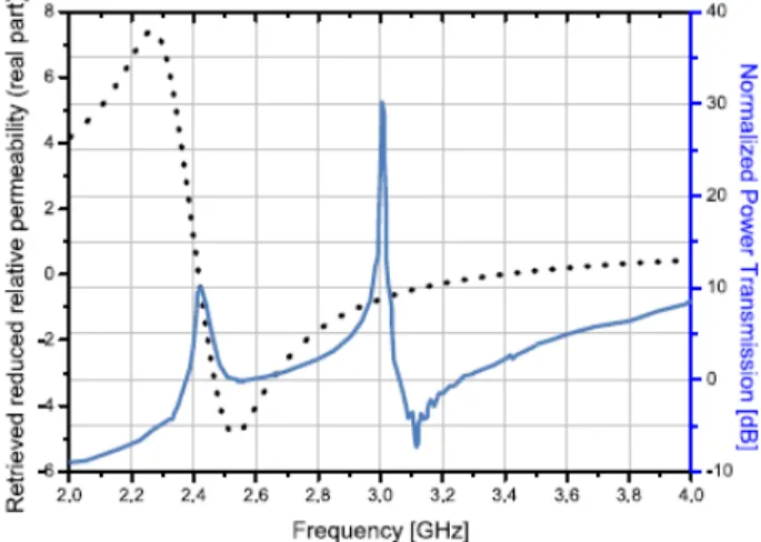
arrangement to get the same reflection/transmission properties of an ideal metamaterial sample for a given polarization and for given sample dimensions. In the case of the sample depicted in Fig. 13, such operative quantities, usually known as Reduced Effective Parameters, have been retrieved for the TEM(z) polarization with the magnetic field aligned along the axis of the rings and for those particular sample dimensions. The reduced permeability of the inclusion arrangement of Fig. 12 is depicted in Fig. 13 where the power transmission is also shown.
As expected, a significant enhancement of the power transmission is obtained at the design frequency: at this very frequency the retrieved reduced permeability equals -1.
The interesting result reported in Fig. 13 suggests an alternative approach, based on a completely different physical phenomenon, in order to get the power transmission through a sub-wavelength aperture.
Fig. 13. Solid line: Simulated power transmission through the aperture as a function of frequency. The plot is normalized to the value of the power transmission at the design frequency (3 GHz) of the structure without any cover. Dotted line: Retrieved reduced relative permeability function (real part) of the inclusion arrangement depicted in Fig. 12. The simulation is performed with the following geometrical parameters: screen extension (10 cm × 10 cm), hole radius (1 mm).
From Fig. 13, in fact, it can be seen that the power transmission is obtained with different values at two different frequencies: one corresponding to an effective reduced permeability equal to -1 and one
corresponding to the resonance of the permeability function, and, thus, to the collective resonance of the split-ring resonators. Therefore, by using an arrangement of magnetic inclusions, it is possible in principle to increase the power transmission through sub-wavelength apertures by using two different resonant approaches. The second resonant peak, i.e. the one due to the resonance of the split-ring resonators, can be easily verified in a real-life fabricated setup. The resonance of the split-rings, in fact, is a phenomenon which can be obtained just by a proper choice of the dimensions of the rings, while the plasmonic like resonance, existing at the virtual interface between the arrangement of split-rings with reduced permeability equal to -1 and the vacuum on the other side of the screen, exhibits more practical issues. In the latter case, the main problems are related to the nature of the virtual interface and to the high sensitivity of the layout to the geometrical dimensions. Due to the aforementioned reasons, the layout based on the proper resonance of the split-rings has been the first to be verified experimentally. In [30] it has been shown how it is possible to use even only one split-ring placed in front of the hole to get the expected enhancement of the transmission. In particular, both of the configurations depicted in Fig. 14 have been tested.
(A) (B)
Fig. 14. Single SRR based setup. In (A) the split is placed along the axis normal to the screen in (B) is placed parallel to the screen. Refer to [30] for the dimensions of the split-rings, the substrate materials, and the details of the experiment.
The configuration of Fig. 14(A) gives better results in terms of power transmission enhancement, because the impinging field is able to excite a strong magnetic dipole moment parallel to the screen as well as a strong electric dipole moment perpendicular to the screen. According to Bethe [1], such dipole moments are responsible for the power transmission and, thus, increasing their amplitude would result also in an increased field intensity on the other side of the metallic screen. Differently from the configuration in Fig. 14 (A), the one depicted in Fig. 14(B) is less efficient since the strong electric dipole moment excited by the impinging field in the split-ring is parallel to the metallic screen and, thus, its contribution is cancelled by its out-of-phase image.
Finally, in Fig. 15 the experimental curves of the power transmission is shown for the two configurations depicted in Fig. 14 (A) and Fig. 14 (B) in the case of a circular split-ring resonating around 3.8 GHz.
Fig. 15. Experimental curves of the power transmission in the cases of the two configurations depicted in Fig. 15. The plots are normalized to the value of the power transmission of the screen with the hole without the split-ring at the design frequency (3.8 GHz). These experimental data come from [31]. Refer to [31] for the dimensions of the split-rings, the substrate materials, and the details of the experiment.
5. Magnetic resonators at Teraertz scale
Unfortunately, the resonant approach based on split-ring resonators at microwaves cannot be straightforwardly applied at the near-infrared
(NIR) and visible frequencies, where many interesting applications are found. A saturation of the operation frequency of metallic resonating inclusions is in fact expected, due to the electron kinetic inductance [31-33].
Magnetic inclusions, which can be successfully used to excite a strong magnetic dipole moment on the aperture, has been recently proposed in [34-36]. In the following, the structure presented in [35], consisting of a gold pillar pair, will be used to enhance the power transmission through a sub-wavelength aperture. The anti-symmetric resonance exhibited by this configuration is able to rise a strong magnetic dipole moment if excited by a TM polarized field with respect to the pillar axis. Placing this magnetic inclusion across or close to a sub-wavelength hole drilled in a silver slab, the power transmission trough the screen would be enhanced in the same fashion as in the SRR case demonstrated in [30].
In addition, the screen is required to be as thin as possible in order to reduce the effect of the material absorption inside the circular aperture. In accordance to the actual fabrication techniques, and differently from [35], a silver layer with hd =50nm thickness is used. In the present case, the pillar pair is also made of silver, modelled through the experimental Drude model retrieved in [38,39]:
2 Au 2 [ ] ∞ = − − p c i ω ε ε ω ν ω (17) where νc = 9 1012 Hz, 15 2 2 10 = p
ω π rad/sec and ε∞ =1. The geometrical layout of the structure is reported in Fig. 16. Such a structure has been excited by a TM plane-wave, having the magnetic field vector normal to the axes of the pillars, impinging on the screen from the pillar side. The excitation of the anti-symmetric mode at the hole plane significantly enhance the tangential magnetic field on the aperture, as shown in Fig. 17(A).
The power transmission curve reported in Fig. 17(B) shows that the power transmission enhancement is obtained exactly at the resonance frequency of the pillar pair ( f0 =300THz) and it is 2.5 times larger than in the case of absence of the pillar pair for a screen transverse size of 700
the pillar dimensions or introducing a dielectric layer between the screen and the pillars. In addition, a dynamic tunability may be envisaged by using thin layers of liquid crystals, as already shown for other metamaterial setups [40]. hg hhdg hd rh ru rb d h l l H E k z x y
Fig. 16. Layout of a silver-nanoparticles based setup. The perforated silver screen is supposed to be deposited on a glass substrate, with thickness hg=10nm. On the other side of the glass substrate, which is the entrance face for the radiation, we put a pillar pair with the following dimensions h=90nm,rb=90nm,ru=85nm,d=225nm. At the expected resonance frequency f0≃300THz of the pillar pair in the anti-symmetric mode, the operating wavelength is λ0≃1 mµ , and, thus, the hole radius rh=25nm is reasonably sub-wavelength (≃λ0/ 40). -500 -400 -300 -200 -100 0 100 200 300 400 500 0.0 0.5 1.0 1.5 2.0 2.5 3.0 3.5 4.0 4.5 5.0 5.5 M a g n e ti c F ie ld A m p lit u d e [ A /m ]x 1 0 5 Position [nm] 250 300 350 0.00 0.05 0.10 0.15 0.20 T ra n s m it ta n c e Frequency [THz] With pillars Without pillars (A) (B)
Fig. 17. (A) Magnetic field amplitude along the axis of the circular aperture (placed at z = 0). The pillar pair is in the negative region. (B) Transmittance for TM illumination of a 700 nm x 700 nm screen. The residual transmittance in the case without the pillars is due to the low conductivity of silver at the considered frequencies.
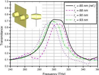
Finally, it is also expected that, by reciprocity, when placing another resonant pair of pillars on the exit face of the screen, the transmission should increase by a factor of four. This hypothesis has also been verified through numerical simulations. In Fig. 18 (solid line), the transmittance is in fact around 10 times higher than in the case of absence of the two pillar pairs. Moreover, the pillar couple on the exit face of the screen introduces a second resonant frequency that, coupling to the one of the first pair, results in broader transmission bandwidth. In order to test the sensitivity of the structure to possible variations of the dimensions due to fabrication tolerances, in Fig. 18 we also report the transmittance for different values of the upper base radius of the silver pillars. These results confirm the robustness of the design.
240 260 280 300 320 340 360 0.0 0.1 0.2 0.3 0.4 0.5 0.6 0.7 0.8 0.9 1.0 T ra n s m it ta n c e Frequency [THz] ru = 85 nm (ref.) r u = 88 nm ru = 90 nm r u = 93 nm
Fig. 18. Transmittance for TM illumination of a 700 nm x 700 nm silver screen with two pillar pairs placed symmetrically on both entrance and exit faces. The solid line refers to the case with the same geometrical dimensions of the pillars as in the previous setups. The dashed and dotted lines, instead, present the variation of the transmittance by changing the radius of the upper base of the pillars (the case ru = 90 nm corresponds to cylindrical pillars).
6. Conclusions
Different resonant approaches for power transmission enhancement trough sub-wavelength apertures at both microwave and optical frequencies have been presented.
From the FSS cover to the silver nano-particles, a set of suitable structures, characterized by a decreasing overall space occupancy and complexity and increasing performances, have been shown.
The FSS approach is successful in enabling the design of a real-life structure whose behaviour is equivalent to an ideal homogeneous metamaterial slab. A design formula for the FSS surface impedance has been derived for both TE and TM polarizations of the impinging field, using a TL circuit equivalent model. The given analytical models have been validated through proper full-wave. Finally, the possibility of using a proper combination of both inductive and capacitive FSSs, placed at one side of the screen, has been investigated, leading to the result that, if the overall thickness of the structure is electrically small, the tolerances to the incidence angle of the impinging radiation and to the real part of the surface impedance can be, in principle, significantly improved.
The SRR-based setup owns, instead, the important advantage of being more compact compared to the FSS-based setup being not based on the excitation of leaky modes. Two working frequencies have been found: one due to the proper resonance of the SRR array, the other due to the satisfaction of the conjugate matched pair condition.
We have shown that the same approach can be also extended at visible frequencies by employing plasmonic pillar pairs working in the anti-resonant mode. Finally, it has been shown that by using a symmetric setup consisting of two identical pillar pairs placed at both faces of the screen it is possible to further increase the transmittance (up to 10 times) and broaden the frequency bandwidth.
Such structures may find applications in different fields, such as high-resolution spatial filters, ultra-diffractive imaging systems, high-capacity optical memories, improved light throughput NSOM tips, etc.
References
1. H.A. Bethe, Phys. Rev. Vol. 66, 163-182 (1944).
2. F. J. Garcia de Abajo, “Light transmission through a single cylindrical hole in a metallic film,” Opt. Express 10, 1475-1484 (2002)
3. Che-Wei Chang, A.K. Sarychev, and V.M. Shalaev, Laser Phys. Lett. , No. 7, pp. 351-355 (2005)
4. D.E. Grupp, Henri J. Lezec, T. Thio, and T. W. Ebbesen, Advanced Materials Vol. 11, pp. 860-862 (1999)
5. A.A. Oliner and D.R. Jackson, in Proceedings of the IEEE AP-S Symposium & URSI Meeting, pp. 1091-1094 (2003)
6. L. Martín-Moreno, F. J. García-Vidal, H. J. Lezec, K. M. Pellerin, T. Thio, J. B. Pendry, and T. W. Ebbesen, Phys. Rev. Lett. 86, 1114 (2001).
7. W. L. Barnes, W. A. Murray, J. Dintinger, E. Devaux, and T. W. Ebbesen., Phys. Rev. Lett. 92, 107401 (2004).
8. R. Gordon, A. G. Brolo, A. McKinnon, A. Rajora, B. Leathem, and K. L. Kavanagh, Phys. Rev. Lett. 92, 037401 (2004).
9. H. J. Lezec, A. Degiron, E. Devaux, R. A. Linke, L. Martin-Moreno, F. J. Garcia-Vidal, and T. W. Ebbesen, Science 297, 820 (2002).
10. F. J. Garcia de Abajo, Opt. Express 10, 1475 (2002). 11. K. J. Webb and J. Li, Phys. Rev. B 73, 033401 (2006).
12. A. Degiron, H.J. Lezec, N. Yamamoto, and T.W. Ebbesen, Opt. Commun. 239, 61 (2004).
13. F. J. García-Vidal, Esteban Moreno, J. A. Porto, and L. Martín-Moreno, Phys. Rev. Lett. 95, 103901 (2005).
14. A. Alù, F. Bilotti, N. Engheta, and L. Vegni, IEEE Trans. Antennas Propagat. Vol. 54, pp. 1632-1643 (2006).
15. A. Alù, F. Bilotti, N. Engheta, L. Vegni, IEEE Trans. Antennas Propagat., Vol. AP-55, No. 3, pp. 882-891 (2007).
16. A. Alù, F. Bilotti, N. Engheta, L. Vegni, Periodic Structures, (M. Bozzi and L. Perregrini, Kerala, India, pp. 271-291, (2006).
17. W. Rotman, Transactions of the IRE, AP , pp. 81-96 (1962).
18. B. Munk, Frequency Selective Surfaces: Theory and Design, (Wiley, New York, 2000).
19. A. Alù, N. Engheta, IEEE Antennas and Wireless Propagation Letters, Vol. 4, pp. 417-420 (2005).
20. A.A. Oliner, IRE Trans. Microw. Theory Tech., Vol. 8, pp. 72-80, 1960 21. CST Studio Suite 2009, http://www.cst.com.
22. F. Bilotti, et al., Journal of Optics A: Pure and Applied Optics 11, 114029, 2009 23. A. Alù, and N. Engheta, IEEE Trans. Antennas Propagat., Vol. AP-51, No. 10, pp.
2558-2570 (2003).
24. Belov P et al, Phys. Rev. B, Vol. 67 113103, (2003).
25. Pendry J B et al, IEEE Trans. Microw. Theory Tech. Vol.47, 2075 (1999). 26. Bilotti F et al, IEEE Trans. Antennas Propag. Vol. 55, 2258 (2007). 27. Bilotti F et al, IEEE Trans. Microw. Theory Tech. Vol. 55, 2865 (2007).
28. F. Bilotti, L. Scorrano, E. Ozbay, and L. Vegni, Journal of Optics A: Pure and Applied Optics, Vol. 11, 114029 (2009).
29. F. Bilotti and L. Vegni, Proc. URSI Gen. Ass. (2008) 30. K. Aydin et al., Phys. Rev. Lett. Vol. 102, 013904 (2009).
31. Stefan Linden, Christian Enkrich, Martin Wegener, Jiangfeng Zhou, Thomas Koschny, Costas M. Soukoulis, Science Vol. 19 (2004)
32. J. Zhou, Th. Koschny, M. Kafesaki, E. N. Economou, J. B. Pendry, and C. M. Soukoulis, Phys. Rev. Lett. 95, 223902 (2005).
33. Sergei Tretykov, Metamaterials 1, Elsevier, pp. 40-43 (2007) 34. G. Dolling et al., Opt. Lett. Vol. 30, 3198-3200, (2005). 35. A.N. Grigorenko et al., Nature Vol. 438, pp. 335-338 (2005).
36. Y. Ekinci, A. Christ, M. Agio, O. J. F. Martin, H. H. Solak, and J. F. Löffler, Optics Express, Vol. 16, Issue 17, pp. 13287-13295 (2008).
37. L. Scorrano, S.Tricarico, F. Bilotti, IEEE Photonics Technology Letters, to appear (2010).
38. D.R. Lide, Handbook of Chemistry and Physics, (CRC Press 2003).
39. Edward D. Palik, Handbook of Optical Constants of Solids, (Academic Press 1998) 40. Q. Zhao et al., Appl. Phys. Lett. Vol. 90, 011112 (2007).
View publication stats View publication stats