Bending Strength of Screwed Corner Joints with
Different Materials
Ali KASAL
1, Sıddık ŞENER
*,2, Çağatay Mehmet BELGİN
2, Hasan EFE
3 1Mugla University, Education of Furniture and Decoration Department, Kostekli 48000, Mugla, TURKEY2Gazi University, Department of Civil Engineering, Maltepe 06570, Ankara, TURKEY
3Gazi University, Education of Furniture and Decoration Department, Teknik okullar, Besevler 06500, Ankara, TURKEY, Received: 06.12.2004 Accepted: 16.06.2006
ABSTRACT
Tests were carried out in order to determine the bending strength with compression and tension force with and without glue in addition to screws on furniture corner joints in a construction case. The specimens were prepared with particleboard and medium density fiberboard (MDF) surfaced with a synthetic resin sheet. In the connection, two types of screws which have dimensions of 4/50 mm and 5/60 mm were used. For the glued joints, polyurethane Desmodur-VTKA adhesive was used. As a result of these tests it has been determined that the joints with glue are better than the ones without glue and the strength of fiberboard is better than particleboard.
Keywords: Bending strength, compression test, tension test, particleboard, wood testing, screws.
*Corresponding author, e-mail: [email protected]
1. INTRODUCTION
As the world population increases, economic conditions are becoming more difficult and life styles and human habits are changing. Life styles will affect furniture. Economic conditions change furniture styles as well. Because of the limited source of wood a lot of research has been conducted on the new type of particleboard and medium density fiberboard with synthetic resin sheet.
Especially at the beginning of the 1950’ s, polyurethane (Desmodur-VTKA) adhesive was developed by the solid wood industry. In general for furniture products, three essential construction methods were used. Furniture was built by the case or frame method or by a combination of the two, the complex method. The case method means that the elements of furniture were plates. In the frame method, the elements of furniture were rods instead of plates. For an efficient design of the case method the furniture constructed using screws with and without glue requires specific design information on the bending strength of corner joints. Several investigations have been made on the corner joints that have yielded data on this design.
Hill and Eckelman [1] carried out a research project in order to determine the flexibility and bending strength
of T type of mortise and tenon joints. Test results indicated that as joint size was increased the average ultimate strength of the joint also increased. Eckelman [2] tested seven different types of commercially available screws which obtained withdrawal resistance from 12 mm thick particleboard specimens. The results of the test indicated that there were practically no differences between the holding strengths of these screws. Zhang and Eckelman [3] carried out research on the bending resistance of single-pin dowel joints in particleboard. Test results indicated that the bending moment resistance of the single dowel corner joints increased significantly either as the dowel diameter increased from 6.4 mm to 19 mm or as the depth of the dowel embedment in the face member increased from 6.4 mm to 15.9 mm. Zhang and Eckelman [4] carried out the bending strength on 171, 229, 279 and 356 mm wide specimens that were constructed with 2 to 5 dowels in order to evaluate the ultimate bending strength of multi-dowel joints and optimum dowel spacings. Test results indicated that the maximum strength per dowel was obtained when dowels were spaced at least 76 mm apart. Results also indicated differences in strength between joints under tension and compression. Eckelman and Lin [5] carried out a research program in order to determine the bending strength of corner joints constructed with injection molded splines. Results indicated that high-strength
joints can be formed by this process, but that the strength of the joints is highly dependent on the configuration of the spline.
Efe [6] tested different woods (scotch pine, oriental beech and oak) using different screw-nuts (through bolt with dowel nut) in pull-out tests. It was observed that the resistance strength of a screw-nut fixture increased as the screw-nut length increased, and decreased as screw-nut diameters increased. Also the withdrawal strength of the screw was affected by the thread height and distance between the threads. Efe and Kasal [7] worked on the case construction with and without glue corner joints under tension. The results were compared. Screwed joints gave better strength than the glued joints with a fiberboard.
Recently studies have been done on the applications of the fracture mechanics in timber joints. Daudeville et. al. [8] carried out a Finite Element method in the framework of Lineer Elastic Fracture Mechanics. The comparison between the experimental and numerical results showed that the main parameter of fracture mechanics was the critical energy release rate in mode I (GIc). This parameter must be considered to improve the
design codes. Jansen et. al. [9] again applied fracture mechanics to the jointed timber parts. The critical energy release rate Gf (GIc) and shear strengths were
calculated along the bond line. Similar fracture energy studies were done on concrete with compression tests by Barr et al [10].
In this study, maximum resistance strengths were compared for the case type corner joints which were made of particleboard and medium density fiberboard with different lengths and screws diameters. These screws were used with and without glue under a static tension and a compression load.
2. TEST MATERIALS
The specimens were prepared with particleboard and a medium density fiberboard surfaced with a synthetic resin sheet. The thickness of all the specimens were chosen as 18 mm. The specimens were produced according to the Turkish standards TS 64 (11) and TS 1770 (12) which are similar to the International Standard Organization ISO-767/1975. The glue (polyurethane) of approximately 200±10 gr/m2 was
used for each joint in the specimens. After the application, specimens were pressed together for approximately 1.5 hours at 200C temperature.
Polyurethane glue has only one component (active glue) which has a high resistance to water and humidity. This glue is excellent for wood, metal, polyester, stone, ceramic, PVC (polyvinyl chloride) and other plastics. It is especially suitable for marine structures and the external face of buildings. The cohessive strength of polyurethane glue is higher than the bonding strength. Glue thickness varied between 0.05 and 0.15 mm during bonding.
Philips head screws which are commonly used for composite plates, were used in the tests. Dimensions of the screws were 4/50 and 5/60 mm. The screws’ material can be steel, aluminium, brass, copper bronze and cadminium. In this test steel screws (sheet metal) were used. The spiral effect of the screws gave a higher strength than the smooth surfaced nails.
3. TEST SPECIMENS AND EXPERIMENTS
To study the bending strength of screwed corner joints with different materials, tests were conducted at Gazi University, Ankara, Turkey. The test specimens are shown in Figure1. In preparing the specimens, full size sheets of particleboard and medium density fiberboard which had the dimensions 2.1×2.8 m were used. Each specimen had two plates named F and B. Dimensions of the face members (F) were 270×150 mm, dimensions of the butt members (B) were 270×132 mm. For glued joints, two plates were combined to each other with glue and 3 screws. A 3 mm diameter pilot hole was drilled before using the screw. For the joints without glue, only 3 screws were used. Screws were drilled to the center of the thickness of butt members. In these tests, two joint type connections with 10 specimens each were tested on two different boards, two different screws and two different loadings. The number of total tests was 2×2×2×2×10=160. Before the experiments, in order to eliminate moisture content variations, specimens were kept in a curing room for one month. The room temperature was 20±20C and the relative
humidity was 65%.
It was observed that the resistance strength of furniture is related to the member materials and joints. As a definition the compression tests are described as the closing of joint agle in Figure 2a and tension tests are described as the opening of joint angle in Figure 2b.
4. ANALYSIS
Test specimens were tested at a 30 kN capacity Seidner bending frame with a 2 mm/min stroke rate under static loading. The tests methods are shown in Figure 2. Under the diagonal compression at the centre of the joint there is an external bending moment.
Mx=Pe, e=P(L+0.5t√2) (1)
where, Mx=calculated bending moment at the center of
the joint, P=measured ultimate axial load,
e=eccentricity of load, and, L=lever arm in the
horizontal direction, t=thickness of the butt elements were 18 mm. From the geometry (Figure 2), L is found as 80.6 mm for compression and as 93.3 mm for tension tests. Resistance of the joints with and without glued screws were considered. In calculating at the surface, the effect of internal friction between the surfaces, dowel action of screws, and shear effects were ignored. During the experimental process, glued joints with screws in L type corner joint elements were under the
normal stress level. The external bending moment according to the center of the joints was given as eq.(1).
Under combined moment and axial force, normal stresses were found as follows:
Figure 1. Test specimens
L
P
D
t/2
P
L
s (a) (b))
6
(cos
2 , 1t
e
A
P
±
=
α
σ
(2) In this formula the effect of shear force was ignored. Ais the area of the connection, A=bt, α=450. In eq.(2), the
subscript 1 stands for the compression face of the joint for which (+) sign of the second term is considered. In the same equation the subcript 2 stands for tension face of the joint and for which (-) sign of the second term of the eq.(29 is used. For the contribution of screws, σs is
calculated by σs= s s
DL
n
P
π
045
cos
(3)where, n=number of the screws (3), Ps=loads taken by
screws, D=diameter of screws, Ls=penetration of the
threaded portion of screw (Fig.2). In eq.(3) stresses
were determined for the joints without glue. Total stress is figured as
σ =σg +σs (4)
where, σg=contribution of glue, σ= total stress at the
joint. The screw was penetrated at the middle of the butt member, that is why moment effect will become zero in the eq.(3). Compression test results were given for the particleboard and medium density fiberboard in Table 1. For tension tests, the equations in which P/2 is substituted for P in eq.(1, 2 and 3). Tension test results are given in Table 2 for the same material and joint connections. The mean values of the test results under tension and compression were given in the bottom line of Table 1 and Table 2 with the standard deviations (SD).
Table 1. Measured ultimate axial load as a Newton (N) under the compression
Fiberboard Particleboard Specimen
No
With glue (P) Without glue (Ps) With glue(P) Without glue (Ps)
4/50 5/60 4/50 5/60 4/50 5/60 4/50 5/60 (1) (2) (3) (4) (5) (6) (7) (8) (9) 1 1180 1190 520 910 650 880 420 730 2 920 1200 410 780 730 920 480 650 3 1000 1480 450 810 650 900 500 810 4 1120 1530 680 970 690 850 560 800 5 1150 1520 550 970 580 750 510 680 6 920 1500 500 820 680 850 530 800 7 1150 1420 450 870 810 910 480 650 8 1180 1150 550 900 820 600 520 620 9 1100 1100 700 700 800 800 480 620 10 1110 1330 650 950 620 840 520 700 Mean (N) 1083 1342 546 868 703 830 500 706 SD (N) 100 169 101 89 84 96 88 75
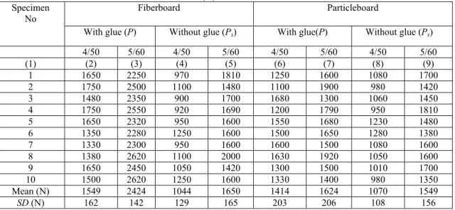
Table 2. Measured ultimate axial load as a Newton (N) under the tension
Fiberboard Particleboard Specimen
No
With glue (P) Without glue (Ps) With glue(P) Without glue (Ps)
4/50 5/60 4/50 5/60 4/50 5/60 4/50 5/60 (1) (2) (3) (4) (5) (6) (7) (8) (9) 1 1650 2250 970 1810 1250 1600 1080 1700 2 1750 2500 1100 1480 1100 1900 980 1420 3 1480 2350 900 1700 1680 1300 1060 1450 4 1750 2550 920 1690 1200 1790 950 1810 5 1650 2320 950 1600 1550 1680 1230 1480 6 1350 2280 1250 1600 1500 1650 1280 1380 7 1330 2300 950 1600 1600 1500 1080 1600 8 1380 2620 1100 2000 1630 1920 1050 1600 9 1650 2450 1050 1420 1300 1500 1010 1700 10 1500 2620 1250 1600 1330 1400 980 1350 Mean (N) 1549 2424 1044 1650 1414 1624 1070 1549 SD (N) 162 142 129 165 203 206 108 156
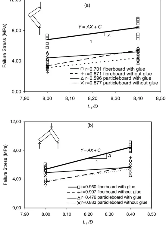
The relation between the bending strength and ratio of depth of screw embedment in the butt members to diameter of screw, for this limited data, was assumed to be a linear function.
Y=AX+C (5)
Where X=ratio of penetration lengths of screws to diameter, Y=failure stress given in eq.(2), A=slope of
the regression line, C=interception of the regression line at the vertical axis in Y. The compression and tension failure stresses are given in Fig.3a and in Fig.3b respectively for two points.
Unfortunately in these tests only two different screw sizes of 4/50 mm and 5/60 mm are used. It is better to have at least three different sizes of screws for generalization.
Y = AX + C
0,00
4,00
8,00
12,00
7,90
8,00
8,10
8,20
8,30
8,40
8,50
L
s/D
F
ai
lur
e S
tr
es
s
(
M
P
a)
r=0.701 fiberboard with glue
r=0.871 fibreboard without glue
r=0.596 particleboard with glue
r=0.877 particleboard without glue
(a)
A
1
Y = AX + C 0,00 4,00 8,00 12,00 7,90 8,00 8,10 8,20 8,30 8,40 8,50 Ls/D F ai lur e S tr es s ( M P a)r=0.950 fiberboard with glue r=0.907 fiberboard without glue r=0.476 particleboard with glue r=0.883 particleboard without glue
(b)
A
1
Figure 3. Test results of joints a)in compression, b)in tension
§
---
-
-
-
-
- -
-
-
-
--
- -
-
- -
---•
- - +
- t:, ... X , ,-
-
-lt- --- --- _____ ..,., -- . -- ---- -- . -- . --~
--•
- - +
--f:ı... x
5. RESULTS
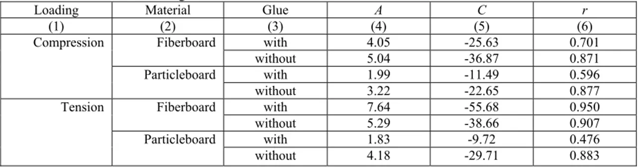
Compression and tension test data results were given in Table 3 using least square methods in linear regression. In this table slope of regression (A), interception of at the vertical axis (C), with correlation coefficients (r)
were given for with and without glue and for particleboards and fiberboards. Best correlation was seen for tests results of fiberboard with glue under tension (r=0.950).
Table 3. Coefficient of linear regression
Loading Material Glue A C r
(1) (2) (3) (4) (5) (6) with 4.05 -25.63 0.701 Fiberboard without 5.04 -36.87 0.871 with 1.99 -11.49 0.596 Compression Particleboard without 3.22 -22.65 0.877 with 7.64 -55.68 0.950 Fiberboard without 5.29 -38.66 0.907 with 1.83 -9.72 0.476 Tension Particleboard without 4.18 -29.71 0.883 Tension strength of glue was affected by the material
type, screw and loading. To determine the contribution of glue average values of load was subsituted in the formula, Pg=P-Ps. Pg was contribution of glue, P was
measured ultimate load with glue, Ps was contribution
of screw, obtained without glue from Table 1,2. From the tests results tension strength of glue eq. (2) was
found maximum for fiberboard under the compression with screw dimension 4/50 as a 3.36 MPa. Average values of test results were used for this calculation. Minimum effect of glue was obtained under the tension for particleboard material and screw dimension 5/60 mm as a 0.27 MPa as seen in Table 4.
Table 4. Tension strength of glue
Loading Material Screw
mm P(with) N Ps(without) N PNg Mom. Nmm MPa σg
(1) (2) (3) (4) (5) (6) (7) (8) 4/50 1083 546 537 50117 3.36 Fiberboard 5/6 1342 868 474 44237 2.97 4/50 703 500 203 18946 1.27 Compression Particleboard 5/60 830 706 124 11573 0.78 4/50 1549 1044 505 26772 1.80 Fiberboard 5/60 2424 1650 774 41033 2.76 4/50 1414 1070 344 18237 1.23 Tension Particleboard 5/60 1624 1549 75 3976 0.27
One type of mode of failure was the opening failure that occurred under the normal forces. Opening failure starts at the edge of the joint and then propagates towards to the top of the joint with increasing load for glued joints. As the glue looses its strength, the screws start to take the load. For some of the glued joints of the particleboards, some board pieces crushed and came out under tension or compression. For the fiberboards especially with 5/60 mm screws some cracks occur in the transverse direction at the edge of board under the opening mode. In the case of joints without glue, opening starts at the edge of joint and ends at the top of the joint with increasing load. After reaching ultimate capacity of joint, load bearing capacity of joints were ended.
6. DISCUSSION and CONCLUSION
Mechanical properties of the case type corner screwed
particleborad and medium density fiberboard under tension and compression. The effect of the screws, materials and glue are seen in the tests results given in Figs.3a for compression and Fig.3b for tension. Glued joints give better performance than the screwed joints as expected. The failure loads of the fiberboard joints was higher than the particleboard joints by 54% with screw 4/50, by 62% with screw 5/60 under compression by 10% with screw 4/50, by 49% with screw 5/60 under tension with glue. This higher strength can be explained by the following reasons. The structural properties of material adhesion and screw holding capacity affect the bending strength, specific gravity of fiberboard is higher than the particleboard. Adhesion of the fiberboard is stronger than the particleboard; the touching point in rough surface particleboard joint is weak; the screw holding capacity is higher in fiberboard than in particleboard.
The 5/60 screws give higher failure loads than the 4/50 mm screws 24% high under compression 56% high under tension for fiberboard with glue as in seen in Table 1-2 and 4. Diameters and lengths of screws affect the strength. As screw diameter and length increases, screw withdrawal resistance increases. According to the test results in Table 1 and 4, screw with glue gives higher load in fiberboard material. Glue gives a load increase for particleboard under compression, which was found out 41% for the 4/50 screws and 18% for the 5/60 screws.
The measured ultimate axial loads under the tension were found as two times of the ultimate axial loads under the compression. The reason for this difference is, the ultimate moment at joint in compression is twice the ultimate moment of tension under the same load. In these tests only two different types of screw size were used. For future studies it is better to have at least three or more screw diameters or lengths.
REFERENCES
[1] Hill, M.D., Eckelman, C.A., “Flexibility and bending strength of mortise and tenon joints”, Furniture Design & Manufacturing magazine, 25-33 (1973).
[2] Eckelman, C.A., “Which screw holds best?” Furniture Design & Manufacturing, magazine 25-26 (1974).
[3] Zhang, J.L., Eckelman, C.A., “The bending moment resistance of single-dowel corner joints in case construction”, Forest Products J, 43(6): 19-24 (1993).
[4] Zhang, J.L., Eckelman, C.A., “Rational design of multi-dowel corner joints in case construction”, Forest Products J, 43(11/12): 52-58 (1993). [5] Eckelman, C.A., Lin, F.C., “Bending strength of
corner joints constructed with injection-molded splines”, Forest Product J , 47(4): 89-92 (1997). [6] Efe, H., “Withdrawal strength of screws on woods
plates were using funiture industry”, Master thesis, Gazi University, Journal of Scienece Knowledge Institute, Ankara, 12-16 (1992). [7] Efe, H., Kasal, A., Tension strength of case
construction with and without demontable corner joints. Industrial Architecture Journal of Faculty of Education Ankara, 8(8): 61-74 (2000).
[8] Daudeville, L., Davenne, L., Yasumura, M., “Prediction of the load carrying capacity of bolted timber joints”, Wood Science and Technology, 33: 15-29 (1999).
[9] Jensen, J.L., Koizumi, A., Sasaki, T., Tamura, Y., Iijima, Y., “Axially loaded glued-in hardwood dowels”, Wood Science and Technology, 35: 73-83 (2001).
[10]
Barr, B.I.G., Abusiaf, H.F., Şener, S., “Size effect and fracture energy studies using compact compression specimens”, RILEM Materials and Structures, 31: 36-41 (1998).[11] Fibre building boards-hard and medium boards (1982) Turkish Code of Practice TS 64.
[12] Fiberboards and particleboards surfaced with synthetic resin (1974) Turkish Code of Practice TS 1770.