Creative Commons CC BY: This article is distributed under the terms of the Creative Commons Attribution 4.0 License (http://www.creativecommons.org/licenses/by/4.0/) which permits any use, reproduction and distribution of
the work without further permission provided the original work is attributed as specified on the SAGE and Open Access pages (https://us.sagepub.com/en-us/nam/open-access-at-sage).
https://doi.org/10.1177/0020294018786743 Measurement and Control 2018, Vol. 51(7-8) 276 –284 © The Author(s) 2018 Article reuse guidelines: sagepub.com/journals-permissions DOI: 10.1177/0020294018786743 journals.sagepub.com/home/mac
Introduction
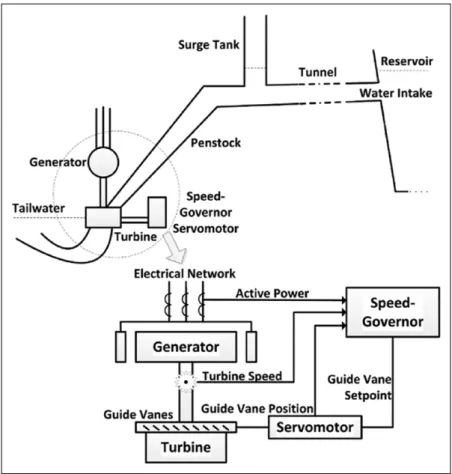
A general layout of a hydroelectric power plant (HEPP) is depicted in Figure 1. Water travels from a reservoir, through tunnel and penstock, to turbine and discharges to tailwater. Except isolated operation, a generating unit is in one of the three modes, namely, standstill, synchronization, and genera-tion. When the unit is started, the speed governor adjusts the turbine speed from standstill to nominal speed to synchronize with the corresponding electrical frequency of the network.
Parameters of the speed-governor controller are typi-cally tuned at the nominal operating conditions such as nominal head and single unit operation. Water-level vari-ations in reservoir and/or tailwater and the presence of other active units sharing the penstock are common dis-turbances to the nominal assumption. They could cause drastic errors in speed control and diminish the synchroni-zation performance of speed governors. The latency in
network synchronization not only prevents the power plant to reach day-ahead generation targets which are committed per hour but also wastes turbined water with-out active power.
The current state-of-the-art for hydraulic turbine control is digital governors, mostly proportional–integral (PI) con-trollers and some with modern control techniques.1 On the classical control side, PI control stability issues2,3 and
Speed control of hydraulic turbines
for grid synchronization using simple
adaptive add-ons
Dogan Gezer
1,2, Yiğit Taşcıoğlu
2and Kutay Çelebioğlu
3Abstract
Background: Parameters of the hydroelectric power plant controllers are typically tuned at the nominal operating
conditions such as nominal head and single unit operation. Water level variations in reservoir and/or tailwater, and the presence of other active units sharing the penstock are common disturbances to the nominal assumption.
Methods: This article proposes two adaptive add-ons, namely gain scheduling and model reference adaptive control, to
the existing speed controllers to improve grid synchronization performance when the site conditions are not nominal. The add-ons were designed and tested on a validated dynamic model of a power plant unit by using a software-in-the-loop simulation setup. An off-season scenario is simulated, in which the original controller of the unit cannot bring the turbine to synchronize with the grid due to low gross head. Then, the add-ons were implemented on-site and experiments were performed under similar conditions. The parameter sets used in gain scheduling for different operation bands are determined off-line with the help of operational experience. The model reference adaptive control add-on requires a reference model and a learning rate. A description of the turbine speed-up profile at nominal operating conditions is sufficient to be used as the reference model. The proposed piecewise linear reference model favors stability over speed in settling to the nominal speed.
Results: It is experimentally shown that the proposed add-ons compensate the negative effect of head loss in grid
synchronization, and perform similar to the ideal performance at the nominal head.
Conclusion: Both add-ons can be implemented on the available off-the-shelf speed governor controllers. They are
suitable for use in all hydroelectric power plants, especially in unmanned ones, for automatic synchronization with less waste water.
Keywords
Model reference adaptive control, gain scheduling, hydroelectric power plant, speed governor, grid synchronization Date received: 26 February 2018; accepted: 9 June 2018
1MRC Energy Institute, TUBITAK, Ankara, Turkey
2Department of Mechanical Engineering, TOBB University of Economics
and Technology, Ankara, Turkey
3ETU Hydro, TOBB University of Economics and Technology, Ankara,
Turkey
Corresponding author:
Yiğit Taşcıoğlu, Department of Mechanical Engineering, TOBB University of Economics and Technology, Sög˘ütözü, Ankara, 06560, Turkey. Email: [email protected]
786743MAC Measurement and ControlGezer et al.
various techniques for determination of PI parameters4–7 are studied by the majority. On the modern control side, studies cover nonlinear, optimal, and robust control through state variable representation. A self-tuning power system stabi-lizer, which uses minimization of the quadratic performance index, is presented in Lim.8 A genetic algorithm is used in Lansberry et al.9 to optimize speed-governor performance of an HEPP. Speed-governor designs with neural networks are explained in Padrón et al.10 for an isolated power system, and in Venayagamoorthy et al.11 by the implementation of neuro-controllers. Robust control of hydraulic turbines through frequency–response technique is presented in Natarajan.12
When the parameters of the plant are unknown or change in time, adaptive control maintains the control system per-formance at a desired level by automatic adjustment of con-trollers in real time.13,14 Gain scheduling (GS) control is an adaptive approach utilizing a look-up table. The controller parameters are automatically picked from the look-up table according to the active operating point, which is deter-mined via an auxiliary measurement.14 For each operating point or band, the parameters are predetermined. GS is used for both active power and speed control of a hydroelectric unit with leaky guide vanes in Doan and Natarajan,15 where the parameters of the controller are changed to control a secondary water input. In Ruzhekov et al.,16 GS is com-pared with the conventional PI controllers in active power control under different load conditions. The advantages of the adaptive approach are shown based on simulations on a nonlinear HEPP model. Model reference adaptive control
(MRAC) aims to improve the closed-loop performance of a plant based on the output of a reference model, which describes the desired behavior of the plant.13 One of the earlier HEPP applications is reported in Vogt et al.,17 where the parameters of a gate position to pressure model is iden-tified based on a reference model. Multiple reference mod-els, depending on load, are used in Puleva and Ichtev18 for both active power and speed control of a hydroelectric unit.
In practice, most of the speed governors are based on classical PI control. This article investigates adaptive add-ons to improve the performance of the existing PI control-lers. The proposed GS and MRAC add-ons are simple enough to be implemented into the existing hardware (i.e. Programmable Logic Controllers PLCs) yet effective to enable network synchronization when the site conditions are not nominal.
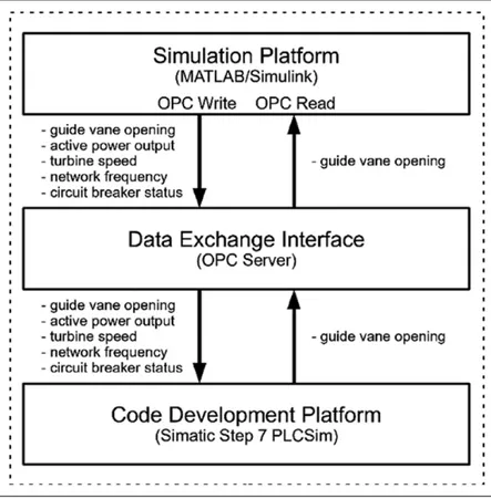
A software-in-the-loop (SIL) simulation setup is con-structed to develop and test the add-ons. SIL tests are cru-cial because they allow thorough investigation and debugging of the controller code before implementation. Failure or unexpected behavior of the controller on-site causes plant outages and may also lead to serious accidents. The SIL setup is composed of a simulation platform, a code development platform, and a data exchange interface. The simulation platform includes a detailed dynamic HEPP model. The code development platform is for writing and testing the controller code to be implemented on the real plant. Data exchange interface transfers relevant signals between two platforms.
278 Measurement and Control 51(7-8)
After SIL simulations, the add-ons were implemented in a single unit of Gezende HEPP during off-season, when the head is lower than the nominal value. The site tests confirm that the proposed add-ons compensate the negative effect of head loss in grid synchronization.
The rest of the article is organized as follows: The SIL setup, along with modeling, implementation, and validation of the dynamic HEPP model, is explained in the “SIL simu-lation setup” section. “GS add-on” and “MRAC add-on” sections provide details of the proposed GS and MRAC add-ons, respectively. The results of simulations and site tests are discussed in the “Results and discussion” section, and the “Conclusion” section concludes the article.
SIL simulation setup
SIL simulation setup is for the design and tests of controller codes on validated dynamic HEPP models. In practice, con-troller codes are usually developed on-site, since the simu-lations cannot completely reflect the real site conditions. On the other hand, a validated dynamic model through site measurements is sufficient for testing the main safety and control actions.
The overview of the SIL setup is shown in Figure 2. The simulation platform contains the mathematical model of the HEPP unit. The code development platform emulates the speed-governor controller. It provides coding tools for the specific industrial control hardware of the speed governor so that the final version of the control code can be directly implemented on-site. Signal interaction between the plat-forms is achieved through a data exchange interface.
HEPP model
Controller design for significant changes in active power out-put and turbine speed of the unit requires nonlinear models,19 which include frictions and hydraulic pressure oscillations.20 Since the focus of the study is on the network synchronization of the unit, meaning that the turbine speed changes from stand-still to nominal speed, the nonlinear HEPP model in Figure 3 is constructed in MATLAB/Simulink. The electromagnetic dynamics of the generator are not considered because of its very short time constant compared to that of hydrodynamics.21 Calculation of the model parameters and derivation of the dif-ferential equations are explained in previous works22–24 and summarized in Supplementary Appendix I.
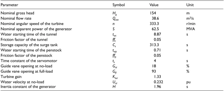
The controllers designed in this study are experimented on a single unit of Gezende HEPP. Gezende is an old plant with three vertical Francis turbines of 53 MW installed capacity each. Its characteristic parameters (Table 1) are applied to the model with the following two assumptions:
• Gezende HEPP has a short-medium penstock and a surge tank; hence, wave propagation is not consid-ered (i.e. Hw = 0).
• Rotating inertia of the turbine is approximately 5% of the generator rotating inertia,23 so that rotating inertia of the unit dominantly depends on the genera-tor characteristic, H.
Speed-governor controller
The speed governor regulates the amount of water enter-ing the turbine by controllenter-ing the guide vane openenter-ing. For
network synchronization, the reference input is the electri-cal grid frequency (ωset), and the feedback is the turbine speed (ω). The speed governor of Gezende HEPP is imple-mented in a Siemens SIMATIC S7 controller, and it utilizes both open-loop and closed-loop modes for speed control, as shown in Figure 4.
At the nominal head, the guide vanes are opened first up to C1 = 25%, until turbine speed reaches 300 r/min (0.9 pu), then the opening is decreased to C2 = 19%, until turbine speed reaches to 317 r/min (0.95 pu). After this point, the closed-loop PI controller takes over. The deadband for the speed error is intentional to provide stable operation by pre-venting oscillations in the guide vane opening. Likewise, the saturation for the guide vane opening setpoint (Gset) is a safety measure.
Model validation
The dynamic model is validated by comparison with the site measurements. Turbine speed of a single unit of Gezende HEPP was increased from standstill to nominal
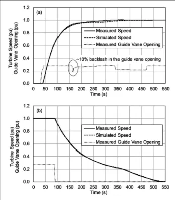
speed (i.e. speed-up), then decreased back to standstill (i.e. shut-down). Turbine speed and guide vane opening values were recorded at every 0.5 s. During the measurements, the head was at the nominal range and one of the neighbor units was active. Then, the measured guide vane opening values were given as time-based workspace input to the MATLAB/ Simulink model (Figure 3). Figure 5 shows the measured and simulated turbine speeds for the same guide vane open-ings. The simulation results correspond to the measure-ments with 0.89% average error and 2.1% maximum error during speed-up, and 0.97% average error and 1.6% maxi-mum error during shut-down.
As a special note, the presence of backlash in the guide vane mechanism has a negative effect on regulation. This effect is especially significant in old plants. As seen in Figure 5(a), although the guide vane opening is decreased by 10% at
t = 165 s, the turbine speed is not affected. The backlash is
handled by a feedforward controller, which adds the amount of backlash to the guide vane setpoint as the direction changes from opening to closing and vice versa.25 The second guide vane dip in Figure 5(a) is a result of this control action.
Figure 3. Generic model of an HEPP unit.
Table 1. Characteristic parameters of Gezende HEPP.
Parameter Symbol Value Unit
Nominal gross head Hg 154 m
Nominal flow rate Qnet 38.6 m3/s
Nominal angular speed of the turbine n 333.3 r/min
Nominal apparent power of the generator S 62.5 MVA
Water starting time of the tunnel twt 8.87 s
Friction factor of the tunnel fft 0.05
Storage capacity of the surge tank Cs 313.3 s
Water starting time of the penstock twp 0.71 s
Friction factor of the penstock ffp 0.05
Time constant of the servomotor ts 4 s
Guide vane opening at no-load Gnl 18 %
Guide vane opening at full-load Gfl 93 %
Turbine gain Ktur 1.33
Water velocity at no-load Unl 0.232 pu
Inertia constant of the generator H 1.96 s
280 Measurement and Control 51(7-8)
GS add-on
Turbine speed controller with GS add-on is shown in Figure 6. The gain scheduler reads the gross head value (Hg) from auxiliary sensors and the number of active units (N) from the top-level controller. It then changes the parameters of the open-loop and closed-loop controllers corresponding to the active operating band (Table 2). The parameters for Gezende HEPP are determined empirically over the years by experienced site operators, and they have been applied manually based on seasonal head measurements.
MRAC add-on
Turbine speed controller with MRAC add-on is shown in Figure 7. The MRAC design is explained in Supplementary
Appendix II. The reference model outputs the desired tur-bine speed. This value is multiplied with the error between the desired and actual speeds, and given as input to the adaptation mechanism. The product is multiplied with the learning rate, Γ, and integrated to produce the coefficient, θ, which manipulates the output of the main controller. It is quicker to achieve the desired behavior by using a larger Γ, but after a critical value, the controller becomes unstable. The output of the MRAC add-on effectively amplifies the gains C1, C2, and Kp, which are set to their nominal (i.e.
Hg = 154 m) values. Since Gezende HEPP is an old plant, the stable range of controller parameters is known from experience (see Table 2). Therefore, θ value is confined between 0.9 and 1.1 by using a saturation block to ensure stability. If the plant were a new project, the stability mar-gin could be found by using the technique presented in Vournas and Papaioannou.26
Reference model for speed control
The desired turbine speed profile is split into eight zones, as shown in Figure 8, and a time-based piecewise linear refer-ence model in Table 3 is constructed. The same profile can also be approximated by using a first-order transfer func-tion as the reference model; however, the proposed approach provides more flexibility in shaping the desired behavior.
Switching from one zone to the next is determined by the actual turbine speed. At each zone, the reference model outputs the desired speed, ωd, from the corresponding equa-tion, where the variable t represents the time spent in that zone.
Results and discussion
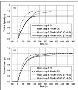
Figure 9(a) shows the performance comparison of control-lers based on the SIL simulations with single unit operation (N = 1) at 0.9 pu gross head. Without the add-ons, the main controller starts in the open-loop mode with C1 = 25%, as it would at the nominal head. The thresholds for switching to
C2 and closed-loop mode are not met because of the head loss; hence, the turbine speed settles at 0.81 pu and fails to
Figure 4. Turbine speed controller of Gezende HEPP.
Figure 5. Measured and simulated turbine speed (Hg = 1 pu,
synchronize with the network. With the GS add-on, the main controller operates with C1 = 30%, C2 = 24%, Kp = 1.4, and Ti = 400 ms, according to Table 2. The response settles smoothly to the nominal speed. This is an expected result since the parameter sets are obtained empirically from the site.
Simulations with the MRAC add-on started with Γ = 0.2. The learning rate is increased until the settling time of the GS add-on is matched with Γ = 0.5. Responses follow that of the main controller until it starts to deviate from the desired behavior. They then adapt to the response of the reference model and settle to the nominal speed. Mode
Figure 6. Turbine speed controller with gain scheduling. Table 2. Parameter sets for gain scheduling in Gezende HEPP.
Gross head (m) N = 1–2 N = 3 Kp Ti C1 (%) C2 (%) C1 (%) C2 (%) 162 ⩽ Hg 22 16 24 18 1.1 700 ms 157 ⩽ Hg< 162 23 17 25 19 1.1 650 ms 152 ⩽ Hg< 157 25 19 27 21 1.2 600 ms 147 ⩽ Hg< 152 28 22 30 24 1.25 600 ms 142 ⩽ Hg< 147 29 23 31 25 1.3 550 ms Hg⩽ 142 30 24 32 26 1.4 500 ms
HEPP: hydroelectric power plant.
282 Measurement and Control 51(7-8)
switching of the main controller at 0.9 and 0.95 pu turbine speed is especially visible in the Γ = 0.2 case.
The simulated controllers are implemented on-site, and the results are shown in Figure 9(b). During the tests, the gross head was 0.95 pu, and one of the other two units was also active (N = 2). The main controller, by itself, fails again to reach the nominal speed. The C2 threshold is met; how-ever, this reduced the already insufficient guide vane open-ing to 19% and the speed remained at 91 pu. The GS add-on and the MRAC add-on with Γ = 0.5 were able to settle to the nominal speed in 280 s, and the MRAC add-on with Γ = 0.2 is 100 s slower.
Results of the site tests with the MRAC add-on are plot-ted in Figure 10 alongside the corresponding reference model outputs and θ values. With Γ = 0.2, θ increases slowly and reaches a maximum value of 1.034. The increase is visible in Figure 10(a) from zone 5 onward (i.e. after 80 s). The higher learning rate causes faster increase in θ and results in a shorter settling time. The maximum value of θ is 1.064, which is below the saturation threshold of 1.1.
The proposed reference model does not have an abso-lute time dependency; instead, it is designed for smoothly guiding the turbine to the nominal speed. This is espe-cially important for grid synchronization. Since there is no active power output, turbine speed can overshoot rap-idly if the guide vanes are opened more than necessary. If the reference behavior were fixed in the time axis (e.g. first-order response), then the accumulating error, espe-cially in the low-head cases, would rapidly increase θ. If this type of reference model is to be used, the intentional saturation in the adaptation mechanism is a safeguard against instability.
Conclusion
Two adaptive add-ons were presented and compared for the grid synchronization of hydraulic turbines. The attractive feature of the proposed add-ons is that they can easily be implemented alongside the existing controllers in the speed governor and aid them when the site conditions are not nominal. A generic dynamic model of an HEPP unit is pre-sented and validated by using experiments on Gezende HEPP site under nominal conditions. Then, this model is used in a SIL setup for controller design and testing before site implementation. A worst-case off-season scenario with 0.9 pu gross head is simulated, in which the original con-troller of the unit cannot bring the turbine to synchronize
Figure 8. Desired turbine speed profile. Table 3. Reference model for turbine speed.
Zone ωstart (pu) ωend (pu) Equation
1 0 0.4 ωd = 0.0150t 2 0.4 0.5 ωd = 0.0100t + 0.4 3 0.5 0.6 ωd = 0.0100t + 0.5 4 0.6 0.7 ωd = 0.0070t + 0.6 5 0.7 0.8 ωd = 0.0060t + 0.7 6 0.8 0.9 ωd = 0.0030t + 0.8 7 0.9 0.95 ωd = 0.0012t + 0.9 8 0.95 1 ωd = 0.0010t + 0.95
Figure 9. Performance comparison of controllers: (a)
simulation (Hg = 0.9 pu, N = 1) and (b) site tests (Hg = 0.95 pu,
N = 2).
Figure 10. Site test results with MRAC add-on (Hg = 0.95 pu,
The MRAC add-on requires a reference model, describ-ing the behavior only at nominal conditions, and a learndescrib-ing rate. The measured turbine speed for model validation is also used for the design of the reference model. The pro-posed piecewise linear reference model favors stability over speed in settling to the nominal speed. It is experimen-tally shown that the MRAC add-on with Γ = 0.5 compen-sates the negative effect of head loss at Hg = 0.95, and performs similar to the original controller at the nominal head. Despite being slower, the turbine speed also settled successfully to the nominal value by using a lower learning rate of Γ = 0.2.
Both add-ons can be implemented on the available off-the-shelf speed-governor controllers. They are suitable for use in all HEPPs but especially in unmanned plants for auto-matic synchronization with less wastewater. To compare the two approaches, the GS add-on is a simpler design requiring a head-level sensor and a look-up table. It can be imple-mented in old plants without modeling and simulation effort, since the gain sets are available from experience. On the other hand, if incorrect scheduling occurs, due to head measurement failure or unforeseen changes in plant dynam-ics, there is no internal feedback for compensation. Design of the MRAC add-on requires a description of the desired nominal behavior, which requires moderate modeling effort not only for new projects but also for old plants. Simulations may be useful to ensure stability and performance, espe-cially for the new projects. Once designed, plant is led to desired operation in closed loop regardless of the plant con-dition, without an auxiliary measurement. The MRAC add-on can be improved to cover active power cadd-ontrol and frequency control loops as future work, along with detailed cost/benefit analyses in design and implementation.
Declaration of conflicting interests
The author(s) declared no potential conflicts of interest with respect to the research, authorship, and/or publication of this article.
Funding
This research is supported by the project “Gezende HEPP Rehabilitation Project” numbered 5112802 and conducted at TUBITAK (Scientific and Technological Research Council of Turkey), Marmara Research Center (MRC) Energy Institute. The authors would like to kindly thank TUBITAK MRC.
York, 27–31 January 2002, pp. 1178–1183. New York: IEEE. 6. Eilts LE and Schleif FR. Governing features and performance
of the first 600-MW drogenerating unit at grand coulee. IEEE Trans Power Appar Syst 1977; 96: 457–466.
7. Filbert TL and Wozniak L. Speed loop cancellation gover-nor for hydrogenerators. II: application. IEEE Trans Energy Convers 1988; 3: 91–94.
8. Lim CM. A self-tuning stabiliser for excitation or governor control of power systems. IEEE Trans Energy Convers 1989; 4: 152–159.
9. Lansberry JE, Wozniak L and Goldberg DE. Optimal hydro-generator governor tuning with a genetic algorithm. IEEE Trans Energy Convers 1992; 7: 623–630.
10. Padrón S, Hernández M and Falcón A. Reducing under-fre-quency load shedding in isolated power systems using neural networks. Gran Canaria: a case study. IEEE Trans Power Syst 2016; 31: 63–71.
11. Venayagamoorthy GK, Harley RG and Wunsch DC. Implementation of adaptive critic-based neurocontrollers for turbogenerators in a multimachine power system. IEEE Trans Neural Networks 2003; 14: 1047–1064.
12. Natarajan K. Robust PID controller design for hydroturbines. IEEE Trans Energy Convers 2005; 20: 661–667.
13. Åström KJ and Wittenmark B. Adaptive control. Boston, MA: Addison-Wesley, 1994.
14. Ioannou PA and Sun J. Robust adaptive control. New York: Dover Books, 1996.
15. Doan RE and Natarajan K. Modeling and control design for governing hydroelectric turbines with leaky wicket gates. IEEE Trans Energy Convers 2004; 19: 449–455.
16. Ruzhekov G, Slavov T and Puleva T. Modeling and implemen-tation of hydro turbine power adaptive control based on gain scheduling technique. In: 16th international conference on intelligent system applications to power systems (ISAP 2011), Hersonissos, Greece, 25–28 September 2011, pp. 1–6. IEEE. 17. Vogt MA, Wozniak L and Whittemore TR. Output error
iden-tification of hydrogenerator conduit dynamics. IEEE Trans Energy Convers 1989; 4: 329–336.
18. Puleva T and Ichtev A. Adaptive multiple model algorithm for hydro generator speed and power control. Control of power plants. AT&P J PLUS 2008; 2: 1–6.
19. Kishor N, Saini RP and Singh SP. A review on hydropower plant models and control. Renew Sustain Energy Rev 2007; 11: 776–796.
20. Ramey DG and Skooglund JW. Detailed hydrogovernor rep-resentation for system stability studies. IEEE Trans Power Appar Syst 1970; 89: 106–112.
21. Munoz-Hernandez GA, Mansoor SP and Jones DI. Modelling and Controlling Hydropower Plants. London: Springer, 2013.
284 Measurement and Control 51(7-8)
22. Melo FP and De Koessler RJ. Hydraulic turbine and turbine control models for system dynamic studies. Trans Power Syst 1992; 7: 167–179.
23. IEEE guide for the application of turbine governing systems for hydroelectric generating units (IEEE Std 1207-2011). New York: IEEE, 2011, pp. 1–139.
24. Murat D, Kosalay I, Gezer D, et al. Validation of hydroe-lectric power plant model for speed governor development studies. In: International conference on renewable energy
research and applications (ICRERA 2015), Palermo, Italy, 22–25 November 2015, pp. 278–282. IEEE.
25. Altay A, Şahin C, Iskender I, et al. A compensator design for the aged hydro electric power plant speed governors. Electr Power Syst Res 2016; 133: 257–268.
26. Vournas CD and Papaioannou G. Modelling and stability of a hydro plant with two surge tanks. IEEE Trans Energy Convers 1995; 10: 368–375.