Tarım Bilimleri Dergisi
Tar. Bil. Der.Dergi web sayfası: www.agri.ankara.edu.tr/dergi
Journal of Agricultural Sciences
Journal homepage: www.agri.ankara.edu.tr/journal
TARIM BİLİMLERİ DERGİSİ
—
JOURNAL OF AGRICUL
TURAL SCIENCES
22 (2016) 317-330
Detection of Shape Manufacturing Defects of Flat Fan-Pattern Nozzle
Orifices Using Elliptic Fourier Descriptors
Bahadır SAYINCIa
aAtatürk University, Faculty of Agriculture, Department of Agricultural Machinery and Technologies Engineering, Erzurum, TURKEY
ARTICLE INFO Research Article
Corresponding Author: Bahadır SAYINCI, E-mail: [email protected], Tel: +90 (442) 231 26 92 Received: 29 December 2014, Received in Revised Form: 24 June 2015, Accepted: 26 June 2015
ABSTRACT
Shape defects originating from the manufacture in the orifice openings of the flat fan-pattern nozzles may result in deteriorating the spray pattern. This study has been conducted with the aim of detecting the manufacturing defects of the fan-pattern nozzle orifices in terms of shape uniformity using the elliptic Fourier descriptors (EFDs), and revealing the shape differences among the nozzle orifices made in polyacetal for various nominal sizes ranging from 01 to 06. At first, descriptive data describing dimensions (major and minor length, projected area, etc.) and shapes (shape factor, elongation and roundness) of the nozzle orifices were obtained using an image processing method. The next process, to evaluate the nozzles’ orifice shape using elliptic Fourier analysis (EFA), the progresses of generating the orifice’s contour data, derivation of EFDs, principal component analysis (PCA) of EFDs and visualization of shape variations estimated by the principal component scores (PCs) were followed respectively. Although the shape differences of the orifice outlines could be visually distinguished, the descriptive shape data were not able to discriminate the contour differences. The EFDs determined for each orifice size could individually detect the nozzle orifices with shape defect originating from the manufacture and they could be explicitly distinguished from the scatter plots. The results of the Hotelling’s pairwise comparison test showed that the nozzle orifices in shape were significantly different from each other. Linear discriminant analysis demonstrated that the group centroids of the orifices of 03, 04 and 06 were found close-range to each other. The orifice of 01 which is rectangular in shape had an extraordinary attribute compared to the other orifices. The orifice outline of 015 with a smooth shape was in appearance of an oblate ellipse in shape. The contour of the nozzle orifice of 02 size was explicitly found different from the others. It was concluded that the EF method can be used intended for the manufacturers inspect and improve the quality of nozzle orifices.
Keywords: Image processing; Nominal size; Orifice contour; Orifice size; Shape analysis
Yelpaze Hüzmeli Meme Orifislerinde Şekilsel Üretim Hatalarının
Eliptik Fourier Tanımlayıcılarıyla Tespiti
ESER BİLGİSİ Araştırma Makalesi
Sorumlu Yazar: Bahadır SAYINCI, E-posta: [email protected], Tel: +90 (442) 231 26 92 Geliş Tarihi: 29 Aralık 2014, Düzeltmelerin Gelişi: 24 Haziran 2015, Kabul: 26 Haziran 2015
Detection of Shape Manufacturing Defects of Flat Fan-Pattern Nozzle Orifices Using Elliptic Fourier Descriptors..., Sayıncı
1. Introduction
Flat fan-pattern nozzles are one of the most widely used for both broadcast and banding spraying of herbicides and insecticides. These nozzles produce a tapered edge, flat-fan spray pattern. This attribute is the most basic distinguishing characteristic for the flat fan-pattern nozzles because their orifice is elliptical in shape and forms a triangular fan. The spray volume of the nozzles is the highest at the center of the pattern and dissipates toward the outer edge of the orifice.
Spray nozzle is the most important and precision component for a sprayer because the nozzles increase pesticide efficacy resulting in better insect, disease and weed control (Dursun et al 2000; Krause et al 2003). These nozzles can wear over time during pesticide application. The nozzle wear may lead to an increase in the nozzle flow rate, a decrease in the spray pressure, making the spray pattern irregular and produce larger droplets (Barber 2006). These occurrences result in ineffective and incautious pesticide use, waste of active gradient, and decrease spray deposition which potentially leads to increase the cost (Krause et al 2003).
In agro-chemical application, the spray nozzles made in polyacetal, stainless steel and ceramic are commonly used. As well as the spray nozzle wear leads to undoubtedly many problems, nozzle manufacturing defects should be also assumed as a significant quality factor affecting the spray performance. It is likely to come across the spray pattern disturbed by new spray nozzles during the nozzle spray test or calibration of any sprayer. There are many reasons for the deterioration of the spray pattern such as clogging, improper re-assembly, restricting flow and corrosion which can be visually detected. However, at first, the high quality standards relating to the manufacturing of the nozzles should be ensured.
The shape defects in the outline of the nozzle’s orifice can be assumed as one of the most important manufacturing defect. Because the shape defects on orifice outline is completely undetectable with the naked eye, the nozzle tests have mostly focused on the change in the flow rate (Reichard et al 1991 cited in Ozkan et al 1992). These tests have been conducted with regard to the procedures standardized by American Society of Agricultural and Biological ÖZET
Yelpaze hüzmeli memelerin orifis açıklığında üretimden kaynaklanan şekilsel hatalar, püskürtme deseninin bozulmasına yol açabilmektedir. Bu çalışma eliptik Fourier tanımlayıcılarını kullanarak yelpaze hüzmeli meme orifislerinin şekil düzgünlüğü açısından üretim hatalarını tespit etmeyi ve anma ölçüleri 01 ve 06 arasında değişen polyacetal malzemeden üretilmiş meme orifislerinin şekil farklılıklarını belirlemek amacıyla yürütülmüştür. Öncelikle, görüntü işleme metodu kullanılarak meme orifislerinin boyut (majör ve minör uzunluklar, izdüşüm alanı vd.) ve şekil (şekil faktörü, uzanım ve dairesellik) özelliklerini tanımlayan deskriptif datalar elde edilmiştir. Eliptik Fourier analiziyle memelerin orifis şeklini değerlendirmek için sonraki süreci sırasıyla orifis kontur datalarını oluşturma, eliptik Fourier tanımlayıcılarını elde etme, tanımlayıcıları temel bileşen analizine tabi tutma ve temel bileşen skorlarıyla tahmin edilen şekil değişkenlerini görselleştirme aşamaları takip etmiştir. Orifis konturlarının şekil farklılıkları gözlem yoluyla ayırt edilebilmesine karşın deskriptif şekil dataları kontur farklılıklarını gözetememiştir. Eliptik Fourier tanımlayıcı üretimden kaynaklanan şekil hatalarına sahip meme orifislerini ayrı ayrı tespit edebilmiş ve saçılım grafiklerinden belirgin bir şekilde ayırt edilebilmiştir. Hotelling eşli karşılaştırma testi sonuçları meme orifislerinin şekil açısından birbirlerinden önemli derecede farklı olduğunu göstermiştir. Doğrusal ayırma analizi sonuçları, 03, 04 ve 06 ölçülü orifislerin grup merkezlerinin birbirlerine oldukça yakın bulunduğunu göstermiştir. Diğerleriyle karşılaştırıldığında dikdörtgen biçiminde olan 01 ölçülü orifis, şekilsel açıdan sıra dışı bir özellik göstermiştir. Pürüzsüz bir kontura sahip olan 015 ölçülü orifisin şekilsel açıdan diğerlerine göre daha basık bir elips görünümünde olduğu saptanmıştır. 02 ölçülü orifis konturu diğerlerinden belirgin bir şekilde farklı bulunmuştur. Üreticilerin meme orifis kalitesini denetlemek ve arttırmak için Eliptik Fourier metodunu kullanabileceği kanısına varılmıştır.
Anahtar Kelimeler: Görüntü işleme; Nominal ölçü; Orifis konturu; Orifis ölçüsü; Şekil analizi
Yelpaze Hüzmeli Meme Orifislerinde Şekilsel Üretim Hatalarının Eliptik Fourier Tanımlayıcılarıyla Tespiti..., Sayıncı
Ta r ı m B i l i m l e r i D e r g i s i – J o u r n a l o f A g r i c u l t u r a l S c i e n c e s 22 (2016) 317-330
319
Engineers organization (ASAE 1991 affirmed in2012). According to these standardized procedures, the flow rate from a used nozzle is compared with the flow rate from a reference nozzle of the same size and type, rather than relying on visual inspection.
Ozkan et al (1992) reported that the spraying pressure, duration of test, type, abrasiveness, concentration of material used in the spray mixture, nozzle type, nozzle size, orifice shape and orifice material were the factors affecting the nozzle wear. It was indicated that much of the difference reported in the nozzle wear rates is due to different operating conditions used when testing nozzles (Krishnan et al 2004). However, the shape defects on a nozzle orifice can result in deteriorating the spray patterns, even though a nozzle’s flow rate conformed to standards at a constant spray pressure.
Special equipment would be required to actually see the changes in the orifice size and shape. The studies conducted by Krause et al (2003) and Krishnan et al (2004) can be presented as an illustration. In these studies, scanning electron microscopy was used in order to observe the new and used fan-pattern nozzle orifices and, indicated that the scanning electron
microscopy can provide nozzle manufacturers with the required information about nozzle to improve performance (Krause et al 2003).
The present study, without a nozzle wear test, aimed to detect the shape defect of fan-pattern nozzle orifices originating from the manufacturing, and to reveal the shape differences and/or similarities of the nozzle orifices with various nominal sizes using elliptic Fourier descriptors.
2. Material and Methods
2.1. Obtaining the orifice images of the nozzles and descriptive analysis
In the study, six flat fan-pattern nozzles, nominal sizes of which ranged from 01 to 06, of 110° spray angle were used and listed in Table 1. The number of each nozzle sample of identical orifice size ranged between 26 and 40. In order to get more information about the nozzles’ design features, the nozzle images, resolutions of which are 2289 × 1752 pixels, were obtained using a stereo zoom microscope (Olympus SZ60, JP) equipped with a digital camera (Panasonic Lumix DMC-FZ50), Table 1- Properties of flat fan-pattern nozzles used in the study and their orifice shapes with regard to the subjective assessment
Çizelge 1- Çalışmada kullanılan yelpaze hüzmeli memelerin özellikleri ve subjektif değerlendirmeye göre orifis şekilleri Technical dimensions and designations Orifice
size Nominal spray angle
Number
of sample Nozzle color code
Orifice
shape Material V-slot angle
(α)
V-slot height (h, mm)
01 110° 40 Orange Rectangular POM* 19° 1.2
015 110° 26 Green Elliptical POM 19° 1.4
02 110° 39 Yellow Elliptical POM 23° 1.3
03 110° 40 Blue Elliptical POM 30° 1.4
04 110° 40 Red Elliptical POM 32° 1.7
06 110° 39 Grey Elliptical POM 28° 1.9
Detection of Shape Manufacturing Defects of Flat Fan-Pattern Nozzle Orifices Using Elliptic Fourier Descriptors..., Sayıncı and the V-slot angle (α°) and height (h, mm)
shown in Table 1 were measured using UTHSCSA ImageTool© version 1.28 CMEIAS software (The University of Texas Health Science Center in San Antonio, TX) after converting the length size in pixel to millimeter unit.
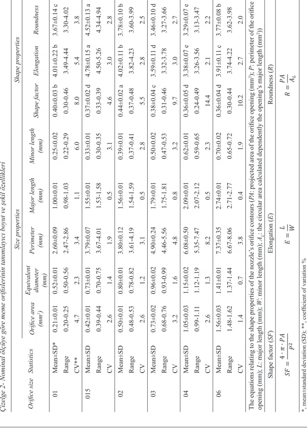
To capture the nozzles’ orifice images, a video microscopy system consisting of a camera, a computer monitor and optics was used. A stereo microscope with 6.3:1 zoom (Leica S6 D, Leica Microsystems, DE) was integrated with a digital microscope color camera (Leica DFC295, Leica Microsystems, DE) offering a standard resolution of 2048 × 1536 pixels. The images were saved on a computer as colored .tiff extension files. SigmaScan®Pro version 5.0 software was used to determine the size and shape features of the orifice openings of the nozzles. The resolution for each image was 2048 × 1536 pixels. During the processing on the image, the region of each nozzle opening with a contrast color was manually marked and automatically colored with the contour of this region. The software automatically determined the opening’s size parameters composing of the projected area (PA, cm2), equivalent diameter (ED, mm), perimeter (P, mm), major length (L, mm) and minor length (W, mm). To reveal the shape features of the orifice openings of the nozzles, shape factor (SF) and elongation (E) (Sayinci et al 2012; Kara et al 2013), and roundness (R) (Mohsenin 1980) parameters, formulas of which were given in Table 2, were used. While the shape factor was also automatically determined by the software, the elongation and roundness parameters were calculated using these equations.
The nozzle orifices’ size and shape data consisting of mean, standard deviation and range were tabulated. To test the variances of the size and shape parameters, the ANOVA with a 95% confidence level (P= 0.05) was performed and, the differences between the means were compared with Duncan’s Multiple Range Comparison test using the SPSS version 20.0 statistical software.
2.2. Elliptic Fourier analysis
To evaluate the nozzles’ orifice shape based on their elliptic Fourier descriptors (EFDs) SHAPE version 1.3 (Iwata & Ukai 2002) software performing the image processing, contour recording, derivation of EFDs, principal component analysis (PCA) of EFDs and visualization of the shape variations estimated by the principal components (PCs) was used.
Prior to the analysis, all digital images were converted to full color (24-bit) bitmap (*.bmp extension file) format. At the beginning of the image processing, the images were split into three colors (RGB) with 8-bit quantization and the orifice images’ background were converted into a binary image (black and white) with an appropriate threshold value which can be also automatically assigned by the software. The closed contour of the orifice on the image came out by edge detection. After the noise reduction applied to eliminate undesirable marks on the image, the contour codes of the orifice with regard to their number were obtained as chain code. The EFDs were obtained from the chain codes and normalized so that the EFDs were invariant with respect to the size, rotation and starting point using elliptic Fourier transformation as suggested Kuhl & Giardina (1982). To generate the coefficient of the normalized EFDs, the first 40 harmonics approximating the shape of each nozzle orifice were used. The PCA based on the variance-covariance matrix was applied to the normalized coefficients of the EFDs having a very large data, and used to reduce the shape descriptors to a smaller number of independent shape variables.
To present the summary of the shape variations of the orifice contours visually and to indicate the percentages of variances explained by PCs, the first two principal component scores obtained from the shape descriptors for each orifice size were tabularized, and the visual differences were presented in figures.
The Multivariate tests (MANOVA) using PAST statistical software version 3.01 (Hammer et al 2001) were performed with the aim of assessing the PC scores obtained from the normalized chain codes
Yelpaze Hüzmeli Meme Orifislerinde Şekilsel Üretim Hatalarının Eliptik Fourier Tanımlayıcılarıyla Tespiti..., Sayıncı
Ta r ı m B i l i m l e r i D e r g i s i – J o u r n a l o f A g r i c u l t u r a l S c i e n c e s 22 (2016) 317-330
321
Table 2- Descriptive size and shape pr
operties of the nozzle orifices with r
egard to their
nominal size
Çizelge 2- Nominal ölçüye gör
e meme orifislerinin tanımlayıcı boyut ve şekil özellikleri
Orifice size Statistics Size pr operties Shape pr operties Orifice ar ea (mm 2) Equivalent diameter (mm) Perimeter (mm) Major length (mm) Minor length (mm) Shape factor Elongation Roundness 01 Mean±SD* 0.21±0.01 0.52±0.01 2.60±0.09 1.00±0.01 0.25±0.02 0.40±0.03 b 4.01±0.22 b 3.67±0.14 c Range 0.20-0.25 0.50-0.56 2.47-2.86 0.98-1.03 0.22-0.29 0.30-0.46 3.49-4.44 3.30-4.02 CV** 4.7 2.3 3.4 1.1 6.0 8.0 5.4 3.8 015 Mean±SD 0.42±0.01 0.73±0.01 3.79±0.07 1.55±0.01 0.33±0.01 0.37±0.02 d 4.78±0.15 a 4.52±0.13 a Range 0.39-0.44 0.70-0.75 3.67-4.01 1.53-1.58 0.30-0.35 0.33-0.39 4.50-5.26 4.34-4.94 CV 2.6 1.4 1.9 0.5 3.1 4.6 3.0 2.8 02 Mean±SD 0.50±0.01 0.80±0.01 3.80±0.12 1.56±0.01 0.39±0.01 0.44±0.02 a 4.02±0.1 1 b 3.78±0.10 b Range 0.48-0.53 0.78-0.82 3.61-4.19 1.54-1.59 0.37-0.41 0.37-0.48 3.82-4.23 3.60-3.99 CV 2.6 1.2 3.1 0.5 2.8 5.5 2.8 2.5 03 Mean±SD 0.73±0.02 0.96±0.02 4.90±0.24 1.79±0.01 0.50±0.02 0.38±0.04 c 3.59±0.1 1 d 3.46±0.10 d Range 0.68-0.76 0.93-0.99 4.46-5.56 1.75-1.81 0.47-0.53 0.31-0.46 3.32-3.78 3.27-3.66 CV 3.2 1.6 4.8 0.8 3.2 9.7 3.0 2.7 04 Mean±SD 1.05±0.03 1.15±0.02 6.08±0.50 2.09±0.01 0.62±0.01 0.36±0.05 d 3.38±0.07 e 3.29±0.07 e Range 0.99-1.1 1 1.12-1.19 5.35-7.47 2.07-2.12 0.59-0.65 0.24-0.49 3.26-3.56 3.13-3.47 CV 2.6 1.3 8.2 0.5 2.3 14.4 2.1 2.2 06 Mean±SD 1.56±0.03 1.41±0.01 7.37±0.35 2.74±0.01 0.70±0.02 0.36±0.04 d 3.91±0.1 1 c 3.77±0.08 b Range 1.48-1.62 1.37-1.44 6.67-8.06 2.71-2.77 0.65-0.72 0.30-0.44 3.74-4.22 3.62-3.98 CV 1.4 0.7 3.8 0.4 1.9 10.2 2.7 2.0 The equations rela ting to the shape properties of the nozzle’ s orifice contours (PA : projected area of the orifice opening (mm 2); P: perimeter of the orifice opening (mm); L: major length (mm); W : minor length (mm); AL
: the circular area calculated dependently the opening’
s major length (mm 2)) Shape factor ( SF ) Elongation ( E) Roundness ( R) Ta ble Descriptiv e s ize a nd sha pe pro pert ies of the no zzle o rif ices w ith reg ard to their n om ina l s ize Ç iz elg e 2 - N omin al ölçü ye g ör e meme o rifis leri nin ta nımla yıcı bo yu t ve ş ekil öz ellikleri Or ifice size Sta tist ics Size p ro pe rties Sha pe pr ope rt ie s Or ifice a re a (m m 2) Eq uiv alen t d ia me ter (m m ) Per ime ter (m m ) M ajo r len gth (m m ) M in or len gth (m m ) Sha pe fac to r El on gat io n Ro un dn es s 01 M ean ±S D * 0. 21± 0. 01 0. 52± 0. 01 2. 60± 0. 09 1. 00± 0. 01 0. 25± 0. 02 0. 40± 0. 03 b 4. 01± 0. 22 b 3. 67± 0. 14 c Ra nge 0. 20 -0. 25 0. 50 -0. 56 2. 47 -2. 86 0. 98 -1. 03 0. 22 -0. 29 0. 30 -0. 46 3. 49 -4. 44 3. 30 -4. 02 CV ** 4.7 2.3 3.4 1.1 6.0 8.0 5.4 3.8 015 M ean ±S D 0. 42± 0. 01 0. 73± 0. 01 3. 79± 0. 07 1. 55± 0. 01 0. 33± 0. 01 0. 37± 0. 02 d 4. 78± 0. 15 a 4. 52± 0. 13 a Ra nge 0. 39 -0. 44 0. 70 -0. 75 3. 67 -4. 01 1. 53 -1. 58 0. 30 -0. 35 0. 33 -0. 39 4. 50 -5. 26 4. 34 -4. 94 CV 2.6 1.4 1.9 0.5 3.1 4.6 3.0 2.8 02 M ean ±S D 0. 50± 0. 01 0. 80± 0. 01 3. 80± 0. 12 1. 56± 0. 01 0. 39± 0. 01 0. 44± 0. 02 a 4. 02± 0. 11 b 3. 78± 0. 10 b Ra nge 0. 48 -0. 53 0. 78 -0. 82 3. 61 -4. 19 1. 54 -1. 59 0. 37 -0. 41 0. 37 -0. 48 3. 82 -4. 23 3. 60 -3. 99 CV 2.6 1.2 3.1 0.5 2.8 5.5 2.8 2.5 03 M ean ±S D 0. 73± 0. 02 0. 96± 0. 02 4. 90± 0. 24 1. 79± 0. 01 0. 50± 0. 02 0. 38± 0. 04 c 3. 59± 0. 11 d 3. 46± 0. 10 d Ra nge 0. 68 -0. 76 0. 93 -0. 99 4. 46 -5. 56 1. 75 -1. 81 0. 47 -0. 53 0. 31 -0. 46 3. 32 -3. 78 3. 27 -3. 66 CV 3.2 1.6 4.8 0.8 3.2 9.7 3.0 2.7 04 M ean ±S D 1. 05± 0. 03 1. 15± 0. 02 6. 08± 0. 50 2. 09± 0. 01 0. 62± 0. 01 0. 36± 0. 05 d 3. 38± 0. 07 e 3. 29± 0. 07 e Ra nge 0. 99 -1. 11 1. 12 -1. 19 5. 35 -7. 47 2. 07 -2. 12 0. 59 -0. 65 0. 24 -0. 49 3. 26 -3. 56 3. 13 -3. 47 CV 2.6 1.3 8.2 0.5 2.3 14. 4 2.1 2.2 06 M ean ±S D 1. 56± 0. 03 1. 41± 0. 01 7. 37± 0. 35 2. 74± 0. 01 0. 70± 0. 02 0. 36± 0. 04 d 3. 91± 0. 11 c 3. 77± 0. 08 b Ra nge 1. 48 -1. 62 1. 37 -1. 44 6. 67 -8. 06 2. 71 -2. 77 0. 65 -0. 72 0. 30 -0. 44 3. 74 -4. 22 3. 62 -3. 98 CV 1.4 0.7 3.8 0.4 1.9 10. 2 2.7 2.0 Th e eq ua tio ns re latin g to th e sh ap e pro pe rti es of th e no zz le’s o rif ice c on to urs (PA : p ro jec ted a re a of th e orif ice o pe nin g (m m 2); P: pe rim et er of th e orif ic e op en in g (m m ); L: m ajo r len gth (m m ); W : m in or len gth (m m ); A L : th e circu lar are a ca lcu late d de pe nd en tly th e op en in g’s m ajo r len gth (m m 2)) Sh ap e fact or (SF ) El ong at io n (E ) Ro un dne ss (R ) 𝑆𝑆𝑆𝑆 = 4 ∙𝜋𝜋 ∙𝑃𝑃𝑃𝑃 𝑃𝑃 2 𝐸𝐸 = 𝐿𝐿 𝑊𝑊 𝑅𝑅 = 𝑃𝑃𝑃𝑃 𝑃𝑃𝐿𝐿 *, m ean ±s ta nd ar d d ev ia tio n ( SD ); * *, co ef fici en t o f v ar iat io n % [𝐶𝐶𝐶𝐶 = (𝑆𝑆𝑆𝑆 𝑀𝑀 𝑀𝑀𝑀𝑀𝑀𝑀 ⁄ )× 10 0] Ta ble Descriptiv e s ize a nd sha pe pro pert ies of the no zzle o rif ices w ith reg ard to their n om ina l s ize Ç iz elg e 2 - N omin al ölçü ye g ör e meme o rifis leri nin ta nımla yıcı bo yu t ve ş ekil öz ellikleri Or ifice size Sta tist ics Size p ro pe rties Sha pe pr ope rt ie s Or ifice a re a (m m 2) Eq uiv alen t d ia me ter (m m ) Per ime ter (m m ) M ajo r len gth (m m ) M in or len gth (m m ) Sha pe fac to r El on gat io n Ro un dn es s 01 M ean ±S D * 0. 21± 0. 01 0. 52± 0. 01 2. 60± 0. 09 1. 00± 0. 01 0. 25± 0. 02 0. 40± 0. 03 b 4. 01± 0. 22 b 3. 67± 0. 14 c Ra nge 0. 20 -0. 25 0. 50 -0. 56 2. 47 -2. 86 0. 98 -1. 03 0. 22 -0. 29 0. 30 -0. 46 3. 49 -4. 44 3. 30 -4. 02 CV ** 4.7 2.3 3.4 1.1 6.0 8.0 5.4 3.8 015 M ean ±S D 0. 42± 0. 01 0. 73± 0. 01 3. 79± 0. 07 1. 55± 0. 01 0. 33± 0. 01 0. 37± 0. 02 d 4. 78± 0. 15 a 4. 52± 0. 13 a Ra nge 0. 39 -0. 44 0. 70 -0. 75 3. 67 -4. 01 1. 53 -1. 58 0. 30 -0. 35 0. 33 -0. 39 4. 50 -5. 26 4. 34 -4. 94 CV 2.6 1.4 1.9 0.5 3.1 4.6 3.0 2.8 02 M ean ±S D 0. 50± 0. 01 0. 80± 0. 01 3. 80± 0. 12 1. 56± 0. 01 0. 39± 0. 01 0. 44± 0. 02 a 4. 02± 0. 11 b 3. 78± 0. 10 b Ra nge 0. 48 -0. 53 0. 78 -0. 82 3. 61 -4. 19 1. 54 -1. 59 0. 37 -0. 41 0. 37 -0. 48 3. 82 -4. 23 3. 60 -3. 99 CV 2.6 1.2 3.1 0.5 2.8 5.5 2.8 2.5 03 M ean ±S D 0. 73± 0. 02 0. 96± 0. 02 4. 90± 0. 24 1. 79± 0. 01 0. 50± 0. 02 0. 38± 0. 04 c 3. 59± 0. 11 d 3. 46± 0. 10 d Ra nge 0. 68 -0. 76 0. 93 -0. 99 4. 46 -5. 56 1. 75 -1. 81 0. 47 -0. 53 0. 31 -0. 46 3. 32 -3. 78 3. 27 -3. 66 CV 3.2 1.6 4.8 0.8 3.2 9.7 3.0 2.7 04 M ean ±S D 1. 05± 0. 03 1. 15± 0. 02 6. 08± 0. 50 2. 09± 0. 01 0. 62± 0. 01 0. 36± 0. 05 d 3. 38± 0. 07 e 3. 29± 0. 07 e Ra nge 0. 99 -1. 11 1. 12 -1. 19 5. 35 -7. 47 2. 07 -2. 12 0. 59 -0. 65 0. 24 -0. 49 3. 26 -3. 56 3. 13 -3. 47 CV 2.6 1.3 8.2 0.5 2.3 14. 4 2.1 2.2 06 M ean ±S D 1. 56± 0. 03 1. 41± 0. 01 7. 37± 0. 35 2. 74± 0. 01 0. 70± 0. 02 0. 36± 0. 04 d 3. 91± 0. 11 c 3. 77± 0. 08 b Ra nge 1. 48 -1. 62 1. 37 -1. 44 6. 67 -8. 06 2. 71 -2. 77 0. 65 -0. 72 0. 30 -0. 44 3. 74 -4. 22 3. 62 -3. 98 CV 1.4 0.7 3.8 0.4 1.9 10. 2 2.7 2.0 Th e eq ua tio ns re latin g to th e sh ap e pro pe rti es of th e no zz le’s o rif ice c on to urs (PA : p ro jec ted a re a of th e orif ice o pe nin g (m m 2); P: pe rim et er of th e orif ic e op en in g (m m ); L: m ajo r len gth (m m ); W : m in or len gth (m m ); A L : th e circu lar are a ca lcu late d de pe nd en tly th e op en in g’s m ajo r len gth (m m 2)) Sh ap e fact or (SF ) El ong at io n (E ) Ro un dne ss (R ) 𝑆𝑆𝑆𝑆 = 4 ∙𝜋𝜋 ∙𝑃𝑃𝑃𝑃 2𝑃𝑃 𝐸𝐸 = 𝐿𝐿 𝑊𝑊 𝑅𝑅 = 𝑃𝑃𝑃𝑃 𝑃𝑃𝐿𝐿 *, m ean ±s ta nd ar d d ev ia tio n ( SD ); * *, co ef fici en t o f v ar iat io n % [𝐶𝐶𝐶𝐶 = (𝑆𝑆𝑆𝑆 𝑀𝑀 𝑀𝑀𝑀𝑀𝑀𝑀 ⁄ )× 10 0] Ta ble Descriptiv e s ize a nd sha pe pro pert ies of the no zzle o rif ices w ith reg ard to their n om ina l s ize Ç iz elg e 2 - N omin al ölçü ye g ör e meme o rifis leri nin ta nımla yıcı bo yu t ve ş ekil öz ellikleri Or ifice size Sta tist ics Size p ro pe rties Sha pe pr ope rt ie s Or ifice a re a (m m 2) Eq uiv alen t d ia me ter (m m ) Per ime ter (m m ) M ajo r len gth (m m ) M in or len gth (m m ) Sha pe fac to r El on gat io n Ro un dn es s 01 M ean ±S D * 0. 21± 0. 01 0. 52± 0. 01 2. 60± 0. 09 1. 00± 0. 01 0. 25± 0. 02 0. 40± 0. 03 b 4. 01± 0. 22 b 3. 67± 0. 14 c Ra nge 0. 20 -0. 25 0. 50 -0. 56 2. 47 -2. 86 0. 98 -1. 03 0. 22 -0. 29 0. 30 -0. 46 3. 49 -4. 44 3. 30 -4. 02 CV ** 4.7 2.3 3.4 1.1 6.0 8.0 5.4 3.8 015 M ean ±S D 0. 42± 0. 01 0. 73± 0. 01 3. 79± 0. 07 1. 55± 0. 01 0. 33± 0. 01 0. 37± 0. 02 d 4. 78± 0. 15 a 4. 52± 0. 13 a Ra nge 0. 39 -0. 44 0. 70 -0. 75 3. 67 -4. 01 1. 53 -1. 58 0. 30 -0. 35 0. 33 -0. 39 4. 50 -5. 26 4. 34 -4. 94 CV 2.6 1.4 1.9 0.5 3.1 4.6 3.0 2.8 02 M ean ±S D 0. 50± 0. 01 0. 80± 0. 01 3. 80± 0. 12 1. 56± 0. 01 0. 39± 0. 01 0. 44± 0. 02 a 4. 02± 0. 11 b 3. 78± 0. 10 b Ra nge 0. 48 -0. 53 0. 78 -0. 82 3. 61 -4. 19 1. 54 -1. 59 0. 37 -0. 41 0. 37 -0. 48 3. 82 -4. 23 3. 60 -3. 99 CV 2.6 1.2 3.1 0.5 2.8 5.5 2.8 2.5 03 M ean ±S D 0. 73± 0. 02 0. 96± 0. 02 4. 90± 0. 24 1. 79± 0. 01 0. 50± 0. 02 0. 38± 0. 04 c 3. 59± 0. 11 d 3. 46± 0. 10 d Ra nge 0. 68 -0. 76 0. 93 -0. 99 4. 46 -5. 56 1. 75 -1. 81 0. 47 -0. 53 0. 31 -0. 46 3. 32 -3. 78 3. 27 -3. 66 CV 3.2 1.6 4.8 0.8 3.2 9.7 3.0 2.7 04 M ean ±S D 1. 05± 0. 03 1. 15± 0. 02 6. 08± 0. 50 2. 09± 0. 01 0. 62± 0. 01 0. 36± 0. 05 d 3. 38± 0. 07 e 3. 29± 0. 07 e Ra nge 0. 99 -1. 11 1. 12 -1. 19 5. 35 -7. 47 2. 07 -2. 12 0. 59 -0. 65 0. 24 -0. 49 3. 26 -3. 56 3. 13 -3. 47 CV 2.6 1.3 8.2 0.5 2.3 14. 4 2.1 2.2 06 M ean ±S D 1. 56± 0. 03 1. 41± 0. 01 7. 37± 0. 35 2. 74± 0. 01 0. 70± 0. 02 0. 36± 0. 04 d 3. 91± 0. 11 c 3. 77± 0. 08 b Ra nge 1. 48 -1. 62 1. 37 -1. 44 6. 67 -8. 06 2. 71 -2. 77 0. 65 -0. 72 0. 30 -0. 44 3. 74 -4. 22 3. 62 -3. 98 CV 1.4 0.7 3.8 0.4 1.9 10. 2 2.7 2.0 Th e eq ua tio ns re latin g to th e sh ap e pro pe rti es of th e no zz le’s o rif ice c on to urs (PA : p ro jec ted a re a of th e orif ice o pe nin g (m m 2); P: pe rim et er of th e orif ic e op en in g (m m ); L: m ajo r len gth (m m ); W : m in or len gth (m m ); A L : th e circu lar are a ca lcu late d de pe nd en tly th e op en in g’s m ajo r len gth (m m 2)) Sh ap e fact or (SF ) El ong at io n (E ) Ro un dne ss (R ) 𝑆𝑆𝑆𝑆 = 4 ∙𝜋𝜋 ∙𝑃𝑃𝑃𝑃 𝑃𝑃 2 𝐸𝐸 = 𝐿𝐿 𝑊𝑊 𝑅𝑅 = 𝑃𝑃𝑃𝑃 𝑃𝑃𝐿𝐿 *, m ean ±s ta nd ar d d ev ia tio n ( SD ); * *, co ef fici en t o f v ar iat io n % [𝐶𝐶𝐶𝐶 = (𝑆𝑆𝑆𝑆 𝑀𝑀 𝑀𝑀𝑀𝑀𝑀𝑀 ⁄ )× 10 0]
Detection of Shape Manufacturing Defects of Flat Fan-Pattern Nozzle Orifices Using Elliptic Fourier Descriptors..., Sayıncı referring to the orifice contours. The similarities
or dissimilarities among the orifice contours were tested using Hotelling’s pairwise comparisons with Bonferroni correction and uncorrected which make possible pairwise comparisons of the orifice contours.
To determine the class/classes of an orifice within orifices with different nominal sizes, linear discriminant analysis (LDA) which is known as Fisher’s linear discriminant analysis or Canonical variate analysis was performed on the PC score data using SPSS statistical software version 20.0.
3. Results and Discussion
3.1. Visual and descriptive evaluation of the orifice shape
In Table 1, the sizes of V-slot angle and its height ranged between 19°-32° and 1.2-1.9 mm, respectively. As the shape of orifices ranged between 02 and 06, sizes were visually elliptical, and the shape of orifice of 01 was rectangular. The V-slot angle and height data in Table 1 are important design parameters in determining the nozzle capacity for flat fan-pattern nozzles. Design parameters such as angle and height concerning the nozzle orifice was in tendency to increase as the orifice size ranging from 01 to 06 increased.
The equivalent diameter and perimeter data of the nozzle orifices given in Table 2 were calculated as a function of orifice area varying between 0.21 and 1.56 mm2. The highest CV within the size parameters was found at the minor length of the orifice of 01, and at perimeter of the orifice of 04. It was noted that the projected area, major and minor length of the orifice linearly increased, as the orifice size varying from 01 to 06 increased as seen in Table 2. Conversely, the CV data decreased as the orifice size increased from 01 to 06. This result showed that the manufacturing defects in the orifices of smaller size are much more than that of the largest ones.
The shape factor, elongation and roundness means in Table 2 ranged between 0.36-0.44, 3.59-4.78 and 3.29-4.52, respectively. As for the CV
data for the shape factor, elongation and roundness parameters, the values varied between 4.6-14.4%, 2.1-5.4%, and 2.0-3.8%, respectively. The CV data in the shape factor were found remarkably higher than the data of the elongation and roundness. All shape descriptive data shows the circularity of the nozzle orifice. If their values were close to 1, this would mean that the shape of the orifice is akin to the circular. These data could be separately evaluated in terms of their shape differentials. However, the result of the Duncan test in Table 2 showed that there were significant differences among the descriptive shape parameters, because they had different variances. It was concluded that there were inconsistencies among three shape descriptions enlightening about the nozzles’ orifice shape. The identical stance was also valid for the CV data of the shape parameters. Basic shape data, such as shape factor, elongation and roundness are acceptable as the most common features for the nozzle orifice shape. However, these data are not able to reveal the shape differentials relating to the manufacturing defect of the nozzle orifices.
3.2. Evaluation of the individual shape variations for each orifice contour
Shape variations between the contours of the orifices based on their first two significant principal components (PCs) were shown in Table 3. Shape contours shown in this table were obtained from the orifice samples analyzed individually for each orifice size. Their first two PCs except the orifice of 015, which had the lowest shape difference, constituted more than fifty percent of the total variance within the shape contour.
In Figure 1, the scatter plots of the first two component scores obtained from the PCA were displayed for the nozzles with different orifice sizes. In these plots, the orifices which are far from the PC1 and PC2 axis were the most deviated samples from the mean in shape.
The figures in Table 3 display prominently the differences of the nozzles’ orifice contour. The orifice of 01 size had the rectangular shape, while the others had an elliptical shape with regard to the
Yelpaze Hüzmeli Meme Orifislerinde Şekilsel Üretim Hatalarının Eliptik Fourier Tanımlayıcılarıyla Tespiti..., Sayıncı
Ta r ı m B i l i m l e r i D e r g i s i – J o u r n a l o f A g r i c u l t u r a l S c i e n c e s 22 (2016) 317-330
323
Table 3- Shape variations in contours of each orifice size with regard to the first two component scores (PCs) obtained from the principal component analysis. The orifice contours from left to right display the PC scores corresponding to: (mean-2 SD, mean, and mean+2 SD)Çizelge 3- Temel bileşenler analizinden elde edilen ilk iki bileşen skorlarına göre her bir orifis ölçüsünün konturlarındaki şekil değişimleri. Temel bileşenler skoruna karşılık gelen orifis konturları soldan sağa doğru: (ortalama-2 SS, ortalama, ortalama+2 SS)
Orifice size explained % of variance -2 SD* Mean +2 SD 01 PC1 (43.0%) PC2 (23.7%) 015 PC1 (31.6%) PC2 (16.9%) 02 PC1 (50.1%) PC2 (20.5%) 03 PC1 (32.4%) PC2 (21.9%) 04 PC1 (35.6%) PC2 (19.7%) 06 PC1 (37.3%) PC2 (27.1%) *, standard deviation
Detection of Shape Manufacturing Defects of Flat Fan-Pattern Nozzle Orifices Using Elliptic Fourier Descriptors..., SayıncıIn Figure 1, the scatter plots of the first two component scores obtained from the PCA were displayed for the nozzles with different orifice sizes. In these plots, the orifices which are far from the PC1 and PC2 axis were the most deviated samples from the mean in shape.
(a) (b)
(c) (d)
(e) (f)
Figure 1- Principal component analysis scatter plot of orifice contours from flat fan-pattern nozzles with six various nominal size; a, orifice of 01 size; b, orifice of 015 size; c, orifice of 02 size; d, orifice of 03 size; e, orifice of 04 size; f, orifice of 06 size (The nozzles shown in ellipsoidal circle display the defective orifices. The orifice contours of the nozzles which is closer to the origin can be accepted as smooth)
Şekil 1- Altı farklı nominal ölçüye sahip yelpaze hüzmeli memenin orifis konturlarına ait temel bileşenler analizi saçılım grafiği; a, 01 orifisi; b, 015 orifisi; c, 02 orifisi; d, 03 orifisi; e, 04 orifisi; f, 06 orifisi (Daire içinde gösterilen memeler kusurlu orifisleri göstermektedir. Orijinine yakın olan memelerin orifis konturları düzgün olarak kabul edilebilir)
-0,06 -0,05 -0,04 -0,03 -0,02 -0,010,00 0,01 0,02 0,03 0,04 -0, 04 -0, 03 -0, 02 -0, 01 0, 00 0, 01 0, 02 0, 03 0, 04 0, 05 0, 06 PC2 (2 3.7 %) PC1 (43.0%)Orifice of 01 -0,06 -0,05 -0,04 -0,03 -0,02 -0,010,00 0,01 0,02 0,03 0,04 -0, 04 -0, 03 -0, 02 -0, 01 0, 00 0, 01 0, 02 0, 03 0, 04 0, 05 0, 06 PC 2 (16. 9% ) PC1 (31.6%)Orifice of 015 -0,06 -0,05 -0,04 -0,03 -0,02 -0,010,00 0,01 0,02 0,03 0,04 -0, 04 -0, 03 -0, 02 -0, 01 0, 00 0,01 0,02 0,03 0,04 0,05 0,06 PC2 (2 0.5 %) PC1 (50.1%)Orifice of 02 -0,06 -0,05 -0,04 -0,03 -0,02 -0,010,00 0,01 0,02 0,03 0,04 -0, 04 -0, 03 -0, 02 -0, 01 0, 00 0,01 0,02 0,03 0,04 0,05 0,06 PC 2 (21. 9% ) PC1 (32.4%)Orifice of 03 -0,06 -0,05 -0,04 -0,03 -0,02 -0,010,00 0,01 0,02 0,03 0,04 -0, 04 -0, 03 -0, 02 -0, 01 0, 00 0, 01 0, 02 0, 03 0,04 0, 05 0, 06 PC2 (1 9.7 %) PC1 (35.9%)Orifice of 04 -0,06 -0,05 -0,04 -0,03 -0,02 -0,010,00 0,01 0,02 0,03 0,04 -0, 04 -0, 03 -0, 02 -0, 01 0, 00 0, 01 0, 02 0, 03 0, 04 0, 05 0, 06 PC 2 (27. 1% ) PC1 (37.3%)Orifice of 06
Figure 1- Principal component analysis scatter plot of orifice contours from flat fan-pattern nozzles with six various nominal size; a, orifice of 01 size; b, orifice of 015 size; c, orifice of 02 size; d, orifice of 03 size; e, orifice of 04 size; f, orifice of 06 size (The nozzles shown in ellipsoidal circle display the defective orifices. The orifice contours of the nozzles which is closer to the origin can be accepted as smooth)
Şekil 1- Altı farklı nominal ölçüye sahip yelpaze hüzmeli memenin orifis konturlarına ait temel bileşenler analizi saçılım grafiği; a, 01 orifisi; b, 015 orifisi; c, 02 orifisi; d, 03 orifisi; e, 04 orifisi; f, 06 orifisi (Daire içinde gösterilen memeler kusurlu orifisleri göstermektedir. Orijinine yakın olan memelerin orifis konturları düzgün olarak kabul edilebilir)
Yelpaze Hüzmeli Meme Orifislerinde Şekilsel Üretim Hatalarının Eliptik Fourier Tanımlayıcılarıyla Tespiti..., Sayıncı
Ta r ı m B i l i m l e r i D e r g i s i – J o u r n a l o f A g r i c u l t u r a l S c i e n c e s 22 (2016) 317-330
325
mean PCs scores. The highest variations in the 01orifice size according to the PC1 score in Table 3 were the size differences at the right and left side of the orifice, which resulted in the enlargement-narrowing or extension-lessening of the side edges of the orifice. Although the orifice of 01 size was rectangular in shape, it had a remarkably irregular contour, and the orifice opening was expanded to just one direction. The highest variations of the orifice of 01 size displayed at PC1 score were determined in the major length/minor length ratio causing the elongation variation.
The major length/minor length ratio of the orifice of 015 in PC1 score had the most important variation in terms of shape differences, while the variation in PC2 score constituted at the side edges of the ellipse. However, the shape differences within the orifice of 015 were the lowest level as seen in Table 3.
It was visually noted that the orifice of 02 size had prominently the largest shape variations. The highest shape defect among the orifice images was almost seen all over the edges of the orifices of 02 size in PC1 score displayed in Table 3. It was concluded that the manufacturing defect for the orifice of 02 size was more apparent compared to the other orifices. The variations in PC2 for the orifice of 02 were not seen in PC1. These variations were the shape defects causing the distortion of the orifice’s ellipse form.
There was a defect at the top-left side of the orifice of 03 in PC1 score compared to the mean PC score displayed in Table 3. This defect reflected to the PC2 score as enlargement-narrowing of the orifice size through the orifice’s external line. The manufacturing defect of the orifice of 04 caused the inferior edge of the orifice for PC1 score. The differences in the 04 orifice in PC2 score originated from the variation of the minor length of the orifice.
Although the highest shape variation among the orifices had been visually seen in the 02 orifice, these distortions could be explicitly seen based on the result of the comparison test of the shape factor mean in Table 2.
In Figure 1, nozzle samples deviating from the mean PC scores were seen, and the shape differences within the nozzles with the identical orifice size could be distinguished. These were displayed within the circular area in the plots. The principal component scores obtained from the elliptic Fourier descriptors which are determined for each orifice size provided to distinguish the nozzles which have the manufacturing defect.
3.3. Comparison of the nozzle orifices with different nominal sizes in terms of shape variation
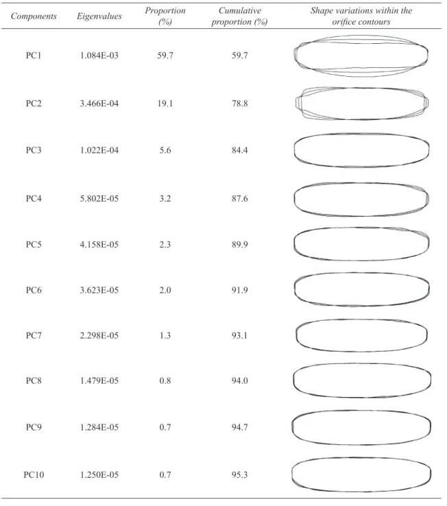
Table 4 presented the relative proportions of the first ten PCs based on a PCA of 224 orifice contours (total sample number for 6 orifice sizes). Each orifice contour was a 40 harmonic reconstruction from elliptic Fourier data. The first ten independent shape variables constituted 95.3% of the total variance. The PC1, PC2, PC3, PC4 and PC5 were the most important scores explaining the proportions of 59.7%, 19.1%, 5.6%, 3.2% and 2.0% of the total variance, respectively. All orifice contours were analyzed together and their variations were seen in Table 4. Variations in the shape resulted from the enlargement or narrowing in minor length of the mean ellipsoidal and rectangular contour for PC1, the narrowing or extension of major length of the ellipse and geometrical shape difference for PC2, the variation of minor length of the ellipsoidal geometry for PC3, the size variations on top-side edges of the rectangular and ellipse geometry for PC4, and the shape destruction on contour for PC5. The proportions in the total variance of the other components ranging from PC6 to PC10 were considerably low, and they displayed smaller differences in the orifice contour in shape.
The results of the MANOVA test were presented in Table 5. The results showed that independent variables which are the first ten principal components (PC1 to PC10) were statistically different at the significance level of 95% (P<0.000) as indicated by Wilks’ Lambda and Pillai Trace statistics. According to the Hotelling’s pairwise comparison results, the orifice shapes of the flat fan-pattern nozzles with different nominal sizes were significantly different
Detection of Shape Manufacturing Defects of Flat Fan-Pattern Nozzle Orifices Using Elliptic Fourier Descriptors..., Sayıncı
Table 4- Eigenvalues and proportions of the first ten principal components (PCs) as shape variables in orifices of 01, 015, 02, 03, 04 and 06, based on a PCA of 224 orifice contours obtained from all nozzle images Çizelge 4- Temel bileşenler analizine göre tüm meme görüntülerinden elde edilen 224 adet temel bileşenin şekil konturuna bağlı olarak belirlenen 01, 015, 02, 03, 04 ve 06’lık orifislere ait şekil değişkenlerinin ilk on temel bileşen yüzdeleri ve öz değer istatistikleri
Components Eigenvalues Proportion (%) proportion (%)Cumulative Shape variations within the orifice contours
PC1 1.084E-03 59.7 59.7 PC2 3.466E-04 19.1 78.8 PC3 1.022E-04 5.6 84.4 PC4 5.802E-05 3.2 87.6 PC5 4.158E-05 2.3 89.9 PC6 3.623E-05 2.0 91.9 PC7 2.298E-05 1.3 93.1 PC8 1.479E-05 0.8 94.0 PC9 1.284E-05 0.7 94.7 PC10 1.250E-05 0.7 95.3
Yelpaze Hüzmeli Meme Orifislerinde Şekilsel Üretim Hatalarının Eliptik Fourier Tanımlayıcılarıyla Tespiti..., Sayıncı
Ta r ı m B i l i m l e r i D e r g i s i – J o u r n a l o f A g r i c u l t u r a l S c i e n c e s 22 (2016) 317-330
327
from each other. Wilk’s Lambda statistic in Table 5is the percent of the variance in the nozzles’ orifice sizes (dependent variables). As the Wilk’s Lambda statistic ranging from 0 to 1 decreased towards 0, the differences between the orifice sizes being analyzed increased. Pillai Trace statistic considered the most reliable among the Multivariate measures takes account of the sum of the variance in the dependent variable that is explained by the greatest discrimination of the independent variables (Foster at al 2006). Both statistics illustrated prominently the differences among the orifice sizes according to the shape discrimination based on the elliptic Fourier descriptors. The results of the Hotelling’s pairwise comparison test demonstrated that the orifice shapes of the nozzles with different nominal sizes had the attributes which are dissimilar to each other.
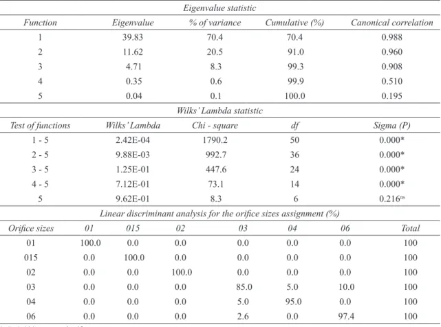
The results of the linear discriminant analysis containing the effects of the canonical discriminant functions were shown in Table 6. The proportion of 96.0% in the classification was correctly grouped in reference to the nozzles’ orifice sizes. The discriminant function analysis in Table 6 was performed using the stepwise method instead of the overall method. For the discriminant analysis, five
canonical functions were obtained. The canonical correlation value is defined as a proportion of the total variance, and indicates the relation between discriminant scores and groups. The canonical correlation value of the first function explained a proportion of 97.6% (square of 0.988) of the total variance in the dependent variables. The second and third ones were the functions explaining a proportion of 92.2% and 82.4% of total variance, respectively. It has been indicated that the eigenvalue statistic which is higher than 0.40 provide the best discrimination in dependent variables (Kalayci 2006). Thus, it could be concluded that the first three discriminant functions in reference to the eigenvalue statistics in Table 6 had a drastic distinctive attribute. The Wilk’s Lambda statistic is defined as an unexplained proportion of the total variance among the groups and the discriminant scores, and the unexplained proportions deduced from the table had a considerably low rate. Table 6 revealed a distinctive attribute among the orifice shapes and demonstrated that the orifice shapes with different nominal sizes of the identical nozzle type were dissimilar to each other. Totally, the proportion of 96.0% in the classification in terms of the orifice shape was located in its own group.
Table 5- Similarities and differences among the nozzle orifices based on their contour variations in shape Çizelge 5- Kontur değişkenlerine bağlı olarak şekilsel açıdan meme orifisleri arasındaki benzerlikler ve farklılıklar
A. MANOVA results (computed in PAST ver. 3.01)
Effects Statistics Value df1 df2 F P (Sigma)
Orifice sizes Wilks’ Lambda 2.42E-04 50 956.6 99.62 0.000*
Pillai Trace 3.019 50 1065 32.46 3.279E-178*
B. The results of the Hotelling’s pairwise comparisons. Bonferroni corrected P - values in lower triangle, P - values uncorrected significance in upper triangle (computed in PAST ver. 3.01)
Orifice sizes 01 015 02 03 04 06
01 1.3E-47 2.4E-57 6.4E-60 3.2E-61 1.5E-59
015 1.9E-46* 1.5E-30 1.4E-34 1.5E-38 1.1E-25
02 3.6E-56 2.2E-29 1.9E-34 4.3E-41 1.8E-31
03 9.6E-59 2.1E-33 2.8E-33 7.4E-13 3.2E-16
04 4.7E-60 2.2E-37 6.5E-40 1.1E-11 2.5E-27
06 2.2E-58 1.7E-24 2.6E-30 4.8E-15 3.8E-26
Detection of Shape Manufacturing Defects of Flat Fan-Pattern Nozzle Orifices Using Elliptic Fourier Descriptors..., Sayıncı
Table 6- Summary of canonical discriminant functions and classification results (%) of the linear discrimination analysis of the PCs obtained from elliptical Fourier descriptors (96.0% of cross-validated grouped cases correctly classified)
Çizelge 6- Kanonik ayırma fonksiyonlarının özeti ve eliptik Fourier tanımlayıcılarından elde edilen temel bileşen skorlarının doğrusal ayırma analizine göre sınıflandırma sonuçları (%) (gruplandırmada % 96 oranında doğru sınıflandırma)
Eigenvalue statistic
Function Eigenvalue % of variance Cumulative (%) Canonical correlation
1 39.83 70.4 70.4 0.988
2 11.62 20.5 91.0 0.960
3 4.71 8.3 99.3 0.908
4 0.35 0.6 99.9 0.510
5 0.04 0.1 100.0 0.195
Wilks’ Lambda statistic
Test of functions Wilks’ Lambda Chi - square df Sigma (P)
1 - 5 2.42E-04 1790.2 50 0.000*
2 - 5 9.88E-03 992.7 36 0.000*
3 - 5 1.25E-01 447.6 24 0.000*
4 - 5 7.12E-01 73.1 14 0.000*
5 9.62E-01 8.3 6 0.216ns
Linear discriminant analysis for the orifice sizes assignment (%)
Orifice sizes 01 015 02 03 04 06 Total
01 100.0 0.0 0.0 0.0 0.0 0.0 100 015 0.0 100.0 0.0 0.0 0.0 0.0 100 02 0.0 0.0 100.0 0.0 0.0 0.0 100 03 0.0 0.0 0.0 85.0 5.0 10.0 100 04 0.0 0.0 0.0 5.0 95.0 0.0 100 06 0.0 0.0 0.0 2.6 0.0 97.4 100 *, P<0.000; ns, non-significant
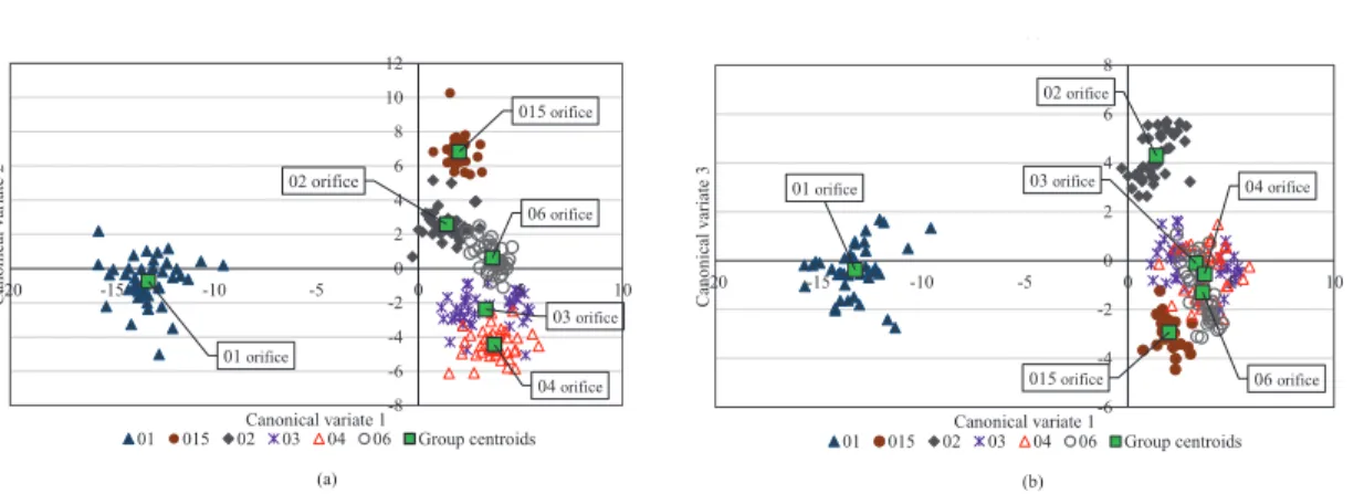
Figure 2 shows the group centroids and orifice distributions in shape based on the PC scores obtained from the linear discriminant function analysis. According to the group centroids of the orifices in Figure 2a showing the relation between the canonical variate 1 and 2, the outmost orifices of the axis were 01 and 015. In the Figure 2b referring to the relation between canonical variate 1 and 3, the 01 and 02 orifices were at the outmost of the axis. The group centroids of the orifices of 03, 04
and 06 were in close-range to each other as seen in both figures. The centroid locations of the orifice groups in Figure 2a and Figure 2b displayed clearly the shape similarities or differences of the orifices with different nominal sizes. The orifice of 01, shape of which is rectangular, had an extraordinary attribute in shape compared to others. Although the orifice of 015 had a smoother shape than the other orifice contours, this orifice has an oblate ellipse in shape. Because of this, this attribute of
Yelpaze Hüzmeli Meme Orifislerinde Şekilsel Üretim Hatalarının Eliptik Fourier Tanımlayıcılarıyla Tespiti..., Sayıncı
Ta r ı m B i l i m l e r i D e r g i s i – J o u r n a l o f A g r i c u l t u r a l S c i e n c e s 22 (2016) 317-330
329
the 015 orifice revealed at the first two canonicaldiscriminant functions. The extraordinary features of the 02 orifice, the manufacturing defect of which is much more than the other orifice, were explicitly seen in Figure 2b. In both Figure 2a and 2b, it could be seen that the group centroids of 03, 04 and 06 orifices were closer than the other. Thusly, the findings and outputs were found compatible with the classification results in the linear discriminant analysis.
4. Conclusions
This study focused to reveal the shape differences among the nozzle orifices made in polyacetal for various nominal sizes ranging from 01 to 06. In the present study, the nozzle orifices with shape defect could successfully be distinguished using shape descriptors obtained from elliptic Fourier analysis (EFA). The elliptic Fourier method provided an excellent discrimination among the polyacetal flat fan-pattern nozzles with various orifice sizes in respect to the orifice’s shape similarities and/or differences, and their shape defects originating from the manufacturing. The orifice shape of the nozzles made from the polyacetal material may be different than those of the other material such as ceramic and stainless steel. Although this study did not have any nozzle wear test study, the results obtained from the study showed that the elliptic Fourier descriptions
will be also able to distinguish the worn nozzles. The next step will be to determine the maximum allowable limits of shape defect disturbing the spray pattern for a nozzle orifice with the experimental studies.
References
ASAE (1991). Standards S471, 1991, Procedure for measuring sprayer nozzle wear rate. ASAE, St. Joseph, Michigan, MI
Barber J (2006). Spray system optimization eases maintenance crunch. Spraying Systems Co. US Dursun E, Karahan Y & Çilingir İ (2000). Türkiye’de
üretilen konik hüzmeli meme plakalarında delik çapı ve düzgünlüğünün belirlenmesi. Tarım Bilimleri
Dergisi-Journal of Agricultural Sciences 6(3): 135-140 Foster J, Barkus E & Yavorsky C (2006). Understanding
and Using Advanced Statistics. Sage Publications, London, pp. 178
Hammer Ø, Harper D A T & Ryan P D (2001). Past: Paleontological statistics software package for education and data analysis. Palaeontologia
Electronica 4(1): article 4, pp. 9
Iwata H & Ukai Y (2002). SHAPE: A computer program package for quantitative evaluation of biological shapes based on elliptic Fourier descriptors. Journal
of Heredity 93(5): 384-385
Kalayci S (2006). SPSS Uygulamalı Çok Değişkenli İstatistik Teknikleri. Asil Yayın, TR, ISBN: 975-9091-14-3, pp. 426
(a)
(b)
Figure 2- Group centroids and distribution of nozzles’ orifices with regard to canonical discriminant functions
Şekil 2- Kanonik ayırma fonksiyonlarına göre meme orifislerinin dağılımı ve grupların merkezi konumu
4. Conclusions
This study focused to reveal the shape differences among the nozzle orifices made in polyacetal for various nominal sizes ranging from 01 to 06. In the present study, the nozzle orifices with shape defect could successfully be distinguished using shape descriptors obtained from elliptic Fourier analysis (EFA). The elliptic Fourier method provided an excellent discrimination among the polyacetal flat fan-pattern nozzles with various orifice sizes in respect to the orifice’s shape similarities and/or differences, and their shape defects originating from the manufacturing. The orifice shape of the nozzles made from the polyacetal material may be different than those of the other material such as ceramic and stainless steel. Although this study did not have any nozzle wear test study, the results obtained from the study showed that the elliptic Fourier descriptions will be also able to distinguish the worn nozzles. The next step will be to determine the maximum allowable limits of shape defect disturbing the spray pattern for a nozzle orifice with the experimental studies.
01 orifice 015 orifice 02 orifice 03 orifice 04 orifice 06 orifice -8 -6 -4 -2 0 2 4 6 8 10 12 -20Cano -15 -10 -5 0 5 10 nica l v ariate 2 Canonical variate 1 01 015 02 03 04 06 Group centroids 01 orifice 015 orifice 02 orifice 03 orifice 04 orifice 06 orifice -6 -4 -2 0 2 4 6 8 -20 -15 -10 -5 0 5 10 Ca no nica l v ariate 3 Canonical variate 1 01 015 02 03 04 06 Group centroids (a) (b)
Figure 2- Group centroids and distribution of nozzles’ orifices with regard to canonical discriminant functions
Şekil 2- Kanonik ayırma fonksiyonlarına göre meme orifislerinin dağılımı ve grupların merkezi konumu
4. Conclusions
This study focused to reveal the shape differences among the nozzle orifices made in polyacetal for various nominal sizes ranging from 01 to 06. In the present study, the nozzle orifices with shape defect could successfully be distinguished using shape descriptors obtained from elliptic Fourier analysis (EFA). The elliptic Fourier method provided an excellent discrimination among the polyacetal flat fan-pattern nozzles with various orifice sizes in respect to the orifice’s shape similarities and/or differences, and their shape defects originating from the manufacturing. The orifice shape of the nozzles made from the polyacetal material may be different than those of the other material such as ceramic and stainless steel. Although this study did not have any nozzle wear test study, the results obtained from the study showed that the elliptic Fourier descriptions will be also able to distinguish the worn nozzles. The next step will be to determine the maximum allowable limits of shape defect disturbing the spray pattern for a nozzle orifice with the experimental studies.
01 orifice 015 orifice 02 orifice 03 orifice 04 orifice 06 orifice -8 -6 -4 -2 0 2 4 6 8 10 12 -20Cano -15 -10 -5 0 5 10 nica l v ariate 2 Canonical variate 1 01 015 02 03 04 06 Group centroids 01 orifice 015 orifice 02 orifice 03 orifice 04 orifice 06 orifice -6 -4 -2 0 2 4 6 8 -20 -15 -10 -5 0 5 10 Ca no nica l v ariate 3 Canonical variate 1 01 015 02 03 04 06 Group centroids
Figure 2- Group centroids and distribution of nozzles’ orifices with regard to canonical discriminant functions
Detection of Shape Manufacturing Defects of Flat Fan-Pattern Nozzle Orifices Using Elliptic Fourier Descriptors..., Sayıncı Kara M, Sayıncı B, Elkoca E, Öztürk İ & Özmen T B
(2013). Seed size and shape analysis of registered common bean (Phaseolus vulgaris L.) cultivars in Turkey using digital photography. Tarım Bilimleri
Dergisi-Journal of Agricultural Sciences 19: 219-234
Krause C R, Reichard D L, Zhu H, Brazee R D, Ozkan H E & Fox R D (2003). Evaluation of fan-pattern spray nozzle wear using scanning electron microscopy.
Scanning 25: 8-11
Krishnan P, Evans T, Ballal K & Kemble L J (2004). Scanning electron microscopic studies of new and used fan nozzles for agricultural sprayers. Applied
Engineering in Agriculture 20(2): 133-137
Kuhl F P & Giardina C R (1982). Elliptic Fourier features of a closed contour. Computer Graphics and Image
Processing 18: 236-258
Mohsenin N N (1980). Physical Properties of Plant and Animal Materials. Structure, physical characteristics and mechanical properties. Gordon and Breach Science Publishers, New York, London & Paris, pp. 742 Ozkan H E, Reichard D L & Sweeney J S (1992). Droplet
size distributions across the fan patterns of new and used nozzles. Transactions of the ASAE 35(4): 1097-1101
Reichard D L, Ozkan H E & Fox R D (1991). Nozzle wear rates and test procedure. Transactions of the ASAE 34(6): 2309-2316
Sayinci B, Ercisli S, Ozturk I, Eryılmaz Z & Demir B (2012). Determination of size and shape in the ‘Moro’ Blood Orange and ‘Valencia’ Sweet Orange cultivar and its mutants using image processing. Notulae
Botanicae Horti Agrobotanici Cluj-Napoca 40(1):