A
COMMUNICATION SCHEME BY
USING SYNCHRONIZED CHAOTIC
SYSTEMS
Omer Morgul and Moez Feki
Bilkent University, Dept.
of
Electrical and Electronics Engineering
06533, Bilkent, Ankara, Turkey
morgulQbilkent .edu. tr moez@ee. bilkent .edu.tr
ABSTRACTA method to synchronize systems with chaotic behavior, in a master-slave configuration adapted t o communication systems, is discussed. This work is motivated by the need for secure communication. In this method, the synchronization and message transmission phases are separated, and while the synchronization is achieved in the synchronization phases, the message is only sent in the message transmission phases.
I. INTRODUCTION
Recently the idea of synchronization of chaotic systems has received a great deal of attention, see e.g. [1]-[4]. One of the motivations for synchroniza- tion is the possibility of sending messages through chaotic systems for secure communication, see e.g. [8], [6], [5]. Such synchronized systems usually con- sist of two parts : a generator of chaotic signals (drive system), and a receiver (response system). The response system is usually a duplicate of a part (or the whole) of the drive system. It has been shown in [2] that by driving the duplicate with sig- nal(s) from the original system, both drive and re- sponse systems will have their common signals syn- chronized.
In this work, we present a method for message transmission using synchronized chaotic systems. In this approach, the synchronization and the message sending phases are alternated. While in one inter- val, drive and response systems are synchronized (synchronization phase (SP)), in the next one, the response system is switched to an autonomous sys-
tem(transmission phase (TP)). Then, at the trans- mitter, the information-bearing signal(message) is added to the chaotic signal, and a t the receiver the masking is removed.
11. COMMUNICATION SCHEME
Assume the following chaotic drive system:
U
= f ( u ),
(U ERn)
(f(
.) is differentiable).Knowing that the solutions of the chaotic system are bounded in a region, and since
f(.)
is differentiable then the following Lipscitz condition is also satisfiedllf(u)
- f(w)ll L:
k l b - W I I,
21, w ER"
,
(1)where
k
>
0 is a Lipschitz constant and the norm1 1 . 1 1
is the-standard Euclidean norm in R".For the response system we consider the follow- ing :
w = g ( u p , w ) , w E R n , u p E R P , where g ( . ) : Rn x
Rn
-+ R? is a differentiable func- tion. Note that the response uses signals of the drive as an input for synchronization. We assume both systems t o be exponentially synchronized, hence there exists constants M>
0 and CY>
0 such that for anyu(0) and w(0) the following holds :
II4t)
- w(t)II L Mf'.-"tl140)-
w(0)ll . (2)Let m(t) be the message to be sent. Let T,
>
0 andT,
>
0 denote the intervals for synchronization andmessage transmission, respectively. Our scheme is as given below :
i
: (Synchronization phase)For 0
5
t<
T,, send the synchronization signal to the response system.ii : (Message transmission phase) For T,
5
t<
T,
+
T,, send the masked message u(t)+
m ( t ) , and for the response system use w = g(w, w) = f(w).
iii
: (Message recovery) For T,5
t
<
T,+
T m ,the recovered message is
m,(t) = u(t)
+
m(t) - w(t).
(3)Note that in the above formulation, it is desir- able t o have p , the dimension of the synchronizing signal, t o be as small as possible. Also, the num- ber of messages to be sent should not exceed the dimension of that portion of the drive system used for synchronization, because the sent message in the TP is simply their sum. Since the error decays to zero in the SP (see [5]), a t the end of this phase these errors become extremely small, provided that
T, is sufficiently large.
It can be easily shown using (1) and (2) that the relation between T, and T, should satisfy the fol- lowing relation:
(4)
where r is the initial error magnitude and E is the
precision number, (i.e. maximum error magnitude in the TP).
I I I. SYNCHRONISATION
We consider the following well-known Lorenz sys- tem for the drive system, see e.g.
[a]
:x =
4 Y
- X I 7y = - z z + r z - y
,
(5)Z = z y - b z
.
with U = 10, T = 20 and b = 1. The solution z ( t ) will be used to synchronize the following response system,
xr = u(yr - z v )
,
Yr = -xZr
+
rz - yr,
(6) 2, = XY,.-
bzr.
It can be proved that if the matrix A of the system
w = Aw
+
f ( t ) is Hurwitz-stable and that f(t) de- creases exponentially to zero, i.e. for some M I>
0 and a1>
0, Ilf(t)ll5
Mle-alt,t2
0, then for any w(0) E R", w(t) also decays exponentially to zero.To prove the synchronization, let us define the synchronization error terms as follows:
e , = 3 : - z r
,
e , = y - y r,
e , = z - z r.
(7)Remark 1 : Since in the TP the synchronization error diverge exponentially, it is quite important to show that these errors decay exponentially in the
SP. Our analysis will emphasize this fact using Lya-
punov function and the above statement.
e, = -xe,
-
ey,
d, = xey-
be,.
(8) Let us define the Lyapunov function V:1 2 1 2
V = -ey
+
-e,.
2 2 (9)
Simple differentiation of V along the solutions of (8)
results in :
V = - e -be, .
Since b
>
0, this shows that all solutions of (8)globally asymptotically decay to zero, see e.g. [9]. Moreover, from (9) and (10) it easily follows that V(t)
5
e-"V(O), wherek
= 2 min{ 1, b } . Moreover, since b = 1, we have V5
-2V, which implies that V ( t )5
e-2tV(0), hence the errors ey ( t ) and e,( t )
in fact decay exponentially to zero. This in particular implies thatI
ey(t)15
e-'lle(O)ll where Ile(S)II =(10)
2 2
Y
$(t)
+
e$(t)+
e,2(t). Then, we have:ex = --bex
+
uey.
(11) Since U>
0 and ey decays exponentially to zero, itfollows from the statment that e, also decays ex- ponentially to zero. The solution of (11) is given as
J o
Hence, by taking norms, using the facts given above and U
>
1, we obtainwhich implies that (2) is satisfied. 0
IV. SIGNAL TRANSMISSION
Consider the systems given by
(5)
and (6). Letm(t) be the message t o be sent. If, in addition to synchronization signal z ( t ) we could send another signal, say y(t), then by sending, say y(t)
+
m(t)
we could recover the message by subtracting yr(t) from this signal. In this case, the message can be recov- ered asymptotically since ey ( t ) decays to zero ex- ponentially fast. However, this scheme requires the transmission of two messages, one for synchroniza- tion and one for message. Alternatively, we could separate the S P and the TP, and at each phase send only one message. For successful synchroniza- tion, T, should be sufficiently large, and this de- pends on the exponential decay rate. Our method for synchronization and message sending is as fol- lows:i : (Synchronization phase ) For 0
5
t<
T,, sendthe synchronization signal z ( t ) , and for the response system use (6).
ii : (Message transmission phase ) For T,
5
t
<
T,+
T,, send z ( t )+
m ( t ) , and for the response system use the following :...
111 : (Message recovery) For T,
5
t<
T,+
T,,the recovered message mr(t) is :
Note that, the response system becomes an au- tonomous system in the TP. Since in the
SP,
the errors e,, ey,
e, decay t o zero exponentially fast, at the end of this phase these errors become extremely small, provided that T, is sufficiently large. Hence, for the TP we could use the variable xr instead of x,which is the rationale behind using (12) instead of (6). Since e,(T,)
#
0, however small, the solutions of (6) and (12) start diverging exponentially fast, and this increase in synchronization error terms de- pends on an appropriate Lyapunov exponent. How- ever, if T, is sufficiently small, which now depends on this Lyapunov exponent, at the end of message transmission phase the synchronization error stillcould remain a t a negligible level. Hence by us- ing (13) we could recover the message. This idea suggests that by making T, larger, we could also be able t o choose larger T, for successful message transmission. Our simulations reveal that the ra-
tio T,/T, should be made smaller than a constant,
which depends on the decay rate in the synchroniza- tion phase and the associated Lyapunov exponent of the drive system. However, the determination of optimum ratio for T,/T, requires further research.
Note that for longer messages, instead of choosing sufficiently large synchronization intervals, we could divide the message into smaller intervals if possible, and then send each part in a message transmission phase, followed by a synchronization phase until all the message is sent.
V. SIMULATIONS
Next we present some numerical simulation re- sults which indicate that the suggested method can be used for successful message transmission and re- covery. Since the state variables in (5) vary in a wide dynamical range, for simulation purposes following [7], we use the scaling z/10, y/10 and 2/20 which results in the following ”scaled” Lorenz system :
y = -20x2
+
r x - y,
i
= 52y-
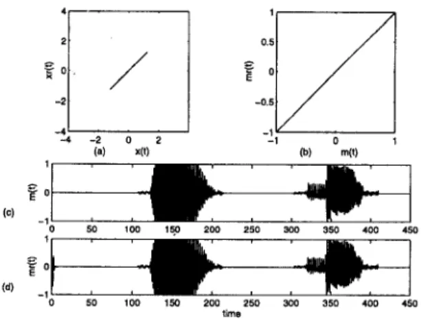
bzand we changed the response systems accordingly. In the first sirhulation, as the message t o be sent, we used the speech signals corresponding the sounds of letters “A” and “B”
.
This message is recovered with good listening quality. In the second simula- tion, the message t o be sent is ”wish you good luck” using the standard international alphabet code no. 2, see [lo]. Figure 2 depicts the message recovery success. In this experiment, we choose smaller am- plitude for the message t o show that using our ap- proach there is no restrictions on message ampli- tude.VI. CONCLUSION
In this work, we presented a method for the sig- nal recovery for the synchronized chaotic systems.
- 0 . 2 -2 -4 -4 -2 0 2 (a) xl!l . . 1
-
E O (e) -1 E O (d)-,
0 1-
0 50 100 150 200 250 300 350 400 I O !,meFig. 1. Transmission of sounds “A” and “B”.(a)Drive vs Response signals.(b)Transmitted vs recovered mes- sages. (c)Transitted message. (d)Received message.
0.05 X in 0.05 % O 50 100 150 200 -0.05 .. e o 0 50 100 150 200 Ume -0.1
Fig. 2. Transmission of coded message.(a)Drive vs Response signals.(b)Transmitted vs recovered messages.(c)Transitted message. (d)Received message.
In this method, the synchronization and the mes- sage sending phases are alternated. This approach has the advantage of using only one transmission channel, in addition t o providing freedom for the message magnitude.
REFERENCES
[3] L. 0. Chua, L. Kocarev, and K. Eckert, “Ex- perimental chaos synchronization in Chua’s cir- cuit,” Int. J. Bifurcation Chaos, vol. 2, pp. 705-
708, 1992.
M. J . Ogorzalek, “Taming chaos - Part 1 : syn- chronization,” IEEE Trans. Circuits Sysli., vol.
40, pp. 693-699, Oct. 1993.
L. Kocarev, K. S. Halle, K. Eckert, and L. 0.
Chua, “Experimental demonstration of secure communication via chaotic synchronization,”
Int. J. Bifurcation Chaos, vol. 2, pp. 709-713,
1992.
[6] K. S. Halle, C. W . Wu, M. Itoh, and L.
0. Chua, “Spread spectrum communication through modulation of chaos,’’ Int. J. Bifur-
cation Chaos, vol. 3, pp. 469-477, 1993.
K. M. Cuomo, and A. V. Oppenheim, “Circuit implementation of synchronized chaos with applications to communications,” Phys. Rev. Lett., vol. 71, pp. 65-68, 1993.
K. M . Cuomo, A. V. Oppenheim, and S. H. Strogatz, “ Synchronization of Lorenz-based
chaotic circuits with applications t o communi- cations,” IEEE Trans. Circuits Syst., vol. 40,
M. Vidyasagar, M. Vidyasagar, Nonlinear Sys- tems Analysis, Prentice-Hall, Englewood Cliffs,
2nd. ed, 1993, p. 292, p. 153.
[lo] W. D. Gegg, Analog and Digital Communica- tion, John Wiley, New York, 1977, p. 526.
[4] [5] [7] [8] pp. 626-633, 1993. [9]
[l] L. M . Pecora and T. L. Carroll, “Synchroniza- tion in chaotic systems,” Phys. Rev. Lett., vol.
64, pp. 821-824, Feb. 1990.
L. M. Pecora and T. L. Carroll, “Driving sys-
tems with chaotic signals,” Phys. Rev. A , vol.
44, no. 4, pp. 2374-2383, Aug. 1991. [2]