Master Thesis
Thesis submitted for the degree of Master of Science in Manufacturing Technology
Development of intrinsic connection elements to join
composite and metal components for automotive
applications
by Can Adalı
Student Number: 181241
Advisors:
Prof. Dr.-Ing. Markus Stommel
i
Table of Contents
1 Introduction... 1
Background of the research question ... 1
Purpose and Approach ... 2
2 State-of-the-Art ... 4
Composite Materials ... 4
Failure Modes of Woven Fabric Reinforced Composites ... 8
Multi-Material Design and Hybridization ... 14
Finite Element Modeling at Abaqus Environment ... 16
FE Modeling of Plain Weave Textile Composite ... 17
3 Design of Composite Specimens ... 19
The Real Case Scenario – Truck Component ... 19
The Concepts used at the Design of Inserts ... 20
Design of Laminate and Inserts ... 23
The Concepts used at the Design of Inserts ... 23
Laminate Design ... 29
4 Production of the Inserts and Specimens ... 31
Production of Metal Inserts with Laser Cutting ... 32
Production of Polymer Insert with Injection Molding ... 32
Production of Composite Laminates by Hand Lamination ... 38
5 Experiments ... 41
Loading Condition and Clamping Device ... 41
Quasi-Static Pin-Pull through Test ... 43
Results and Discussion of the Experiments ... 59
6 FE Analysis of Pin Pull-Through Test ... 62
Material Properties ... 62
FE Analysis of Reference Specimens ... 64
FE Analysis of Metal Inserted Model ... 71
ii
8 Discussion and Next Steps ... 80
9 References ... 83
10 Appendix ... 87
Material properties for FE Analysis of metal Inserted Specimens ... 87
Calculation of bearing stress and strain of reference specimens ... 87
Elastic Modulus calculation of reference specimens ... 88
Stiffness Calculations of the specimens ... 89
iii
Abstract
The lightweight construction is in great demand in the 21st century with the increasing need for fuel saving, safety concerns and customized material properties. For its high specific strength and customizable material properties, the composite materials have found its place as a major lightweight material in aerospace, marine and automotive industries. One fastening technique to join these composite parts to other components is bolted joining which requires drilling to form the holes. Nevertheless, drilling weakens the properties of the composite enormously. One technique to reinforce the joint is to place inserts in the bearing region during the production of the composite. In this work, three different reinforcement inserts were designed for joint region of a Mercedes-Benz Truck component, namely metal insert (M), polymer insert (P) and metal- polymer insert (MP). Four different types of glass/epoxy, plain weave textile composite (PWTC) specimens were designed. One specimen type is only drilled which is used as reference, and other three specimen types have inserts embedded between their layers. The specimens were tested under quasi-static loading conditions at a two-parallel pinned pull-through test. It is observed that all the inserted specimens have higher ultimate load capacity relative to the reference specimens (up to 44% improvement). Besides, the bearing strength increases up to 74.7% at the non-drilled specimen types. However, placement of inserts leads to significant delamination failure (up to 3mm delamination at polymer inserted specimen). Moreover, the pin pull-through test of reference specimen and metal inserted specimen were modeled in commercial Abaqus FEA software. Stiffness values from FE analysis is in relatively good correlation with experimental stiffness. The stiffness errors for reference and metal inserted specimens are 5% and 39.2% consequently. The non-elastic response of PWTC specimens were not properly represented in the FE models.
iv
List of Figures
Figure 1.1. The workflow of the research ... 2
Figure 2.1. Composite types by shape of reinforcement material. ... 5
Figure 2.2. Types of reinforcement fiber. ... 5
Figure 2.3. Continuous fiber reinforcements ... 7
Figure 2.4. Bergmann’s pin pull-through test ... 8
Figure 2.5. Delamination of the composite plies. ... 9
Figure 2.6. Intra-laminar cracks at PWTC ... 9
Figure 2.7. Kink bands that occur under compression ... 10
Figure 2.8. Microstructure of a PWTC. ... 10
Figure 2.9. Bearing failure modes at drilled and fastened composites ... 11
Figure 2.10. Crush characteristics of the composite under pin compression ... 11
Figure 2.11. Specimen configurations ... 12
Figure 2.12. The transition from elastic to plastic response of specimen W1 ... 13
Figure 2.13. Customized contact zones ... 15
Figure 3.1. The rear cab suspension bracket ... 19
Figure 3.2. The flat surface of the bracket that sits on the chassis. ... 20
Figure 3.3. Hybrid metal-composite connection element ... 20
Figure 3.4. Curved contact surfaces ... 21
Figure 3.5. A commercial Bighead® Insert ... 21
Figure 3.6. Curved contact surface designed at this work. ... 21
Figure 3.7. The pin socket design of this work ... 22
Figure 3.8. The three types of designed inserts. ... 22
Figure 3.9. Section of the metal-polymer hybrid insert. ... 23
Figure 3.10. The sheet metal insert with plain bearing socket ... 24
Figure 3.11. The cross-section dimensions of the composite laminate with metal insert ... 24
Figure 3.12. The cross-section of the composite laminate with metal insert ... 24
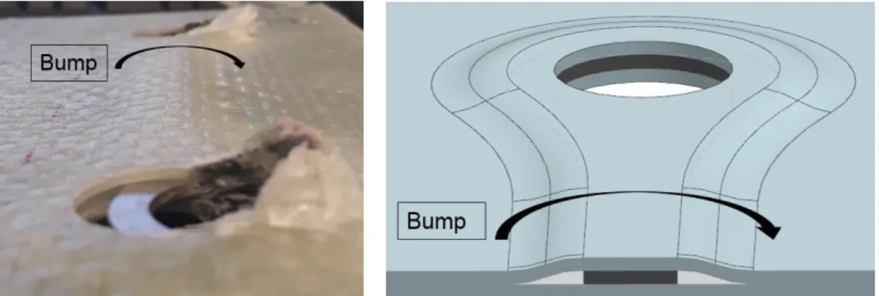
Figure 3.13. The bump at the metal inserted specimen ... 24
Figure 3.14. Tows of glass fibers are directed around the collar ... 25
Figure 3.15. Change of distance between fiber tows due to collar ... 25
Figure 3.16. Cross sectional dimensions of the composite laminate with metal-polymert ... 26
Figure 3.17. Cross-section of the composite laminate with polymer insert ... 26
Figure 3.18. The inclined contact zone at the polymer inserted specimen ... 26
Figure 3.19. Dimensions of the metal-polymer insert ... 27
Figure 3.20. Cross-section dimensions of the composite laminate with metal-polymer insert 27 Figure 3.21. The cross-section of the composite laminate with metal-polymer insert ... 27
Figure 3.22. Sharp edges of the polymer and metal-polymer inserts. ... 28
Figure 3.23. The inclined contact zone at the metal-polymer inserted specimen ... 28
v
Figure 3.25. Dimensions of the composite specimen ... 29
Figure 3.26. E-glass plain weave fabric ... 30
Figure 4.1. Pictures of produced inserts. ... 31
Figure 4.2. Laser Cutting Machine, Retrieved from Kistner Machine Tools32 Figure 4.3. Injection Molding Machine - Arburg 270 S. ... 33
Figure 4.4. Injection molding tools ... 33
Figure 4.5. Surface structure cavities on the mold plate ... 34
Figure 4.6. Plastic Injection machine ... 35
Figure 4.7. Ultrasonic Vibration Machine and Cleaning Agent. ... 35
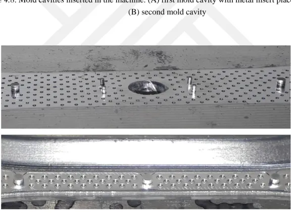
Figure 4.8. Mold cavities inserted in the machine ... 36
Figure 4.9. Support pins to hold the metal in the middle of the cavity ... 36
Figure 4.10. Good and poor surface-to-surface adhesion between polymer and metal ... 37
Figure 4.11. Cracks on the polymer and diesel defect on the polymer bearing ... 38
Figure 4.12. Poor filling of the cavity at injection molding process ... 38
Figure 4.13: Woven Fabric Roll and Fabric Plies ... 39
Figure 4.14: Drilled inserts: Reference laminate and Metal inserted laminate ... 40
Figure 4.15. Non-Drilled, Polymer inserted Laminate... 40
Figure 4.16. Non-drilled, metal-polymer inserted laminate. ... 40
Figure 5.1. Loads on the bracket ... 42
Figure 5.2 . Specimen with pins, specimen with clamps ... 42
Figure 5.3. Experiment ready setup. ... 43
Figure 5.4. Dimensions of the specimens and pin pull-through direction ... 44
Figure 5.5. Bearing mode failure of four types of specimens ... 45
Figure 5.6. The crush of the composite around the hole as the pin moves through ... 45
Figure 5.7. Bearing crush at this work. Schematic representation of bearing ... 46
Figure 5.8. Failure at reference specimens ... 46
Figure 5.9. Force - hole displacement plots of the reference specimens ... 47
Figure 5.10. The stress – strain plots of reference specimens ... 49
Figure 5.11. Failure at metal inserted specimens ... 49
Figure 5.12. Bending of metal insert ... 50
Figure 5.13. Force - hole displacement plots of the metal inserted specimens ... 51
Figure 5.14. The failure at polymer inserted specimens ... 52
Figure 5.15. Brittle fracture of the polymer ... 52
Figure 5.16. The transition of specimen P2 from elastic to plastic region ... 53
Figure 5.17. Delamination at polymer inserted specimens ... 53
Figure 5.18. Force - hole displacement plots of the polymer inserted specimens ... 54
Figure 5.19. Failure at specimen MP3 ... 55
Figure 5.20. Delamination failure at specimen MP3 ... 55
Figure 5.21. Failure at specimen MP4 ... 56
Figure 5.22. Delamination failure at specimen MP4 ... 56
vi
Figure 5.24. Failure at specimen MP5 ... 57
Figure 5.25. Force - hole displacement plots of the metal-polymer inserted specimens ... 58
Figure 5.26. Elastic region comparison of four types of specimens ... 59
Figure 5.27. Delamination at polymer inserted specimen ... 61
Figure 6.1. Pin pull-through assembly of reference specimen ... 64
Figure 6.2. Each ply is represented with one layer of mesh ... 65
Figure 6.3. Fine mesh around the hole ... 65
Figure 6.4. Pin-composite interface – cross section view ... 66
Figure 6.5. Kinematic coupling between rigid body node and pins ... 67
Figure 6.6. Force-Displacement Curve Comparison of simulation and experiments ... 68
Figure 6.7. The tearing of the fibers due to fiber tension ... 69
Figure 6.8. Instances from the F-X plot ... 70
Figure 6.9. Absolute Principal Stresses at elastic region points and point C. ... 70
Figure 6.10. After the damage initiation, tensile stresses in x-direction emerges. ... 71
Figure 6.11. The assembly of M Laminate ... 71
Figure 6.12. Kinematic coupling between rigid body node and pins ... 72
Figure 6.13. Pure resin body fills the gap between metal insert and composite laminate ... 72
Figure 6.14. Pure resin body is hidden and Pure resin body is visible ... 73
Figure 6.15. The green surface represents the cohesive zero thickness mesh surface ... 74
Figure 6.16. Pins pull the metal insert and compress the composite ... 74
Figure 6.17. Slide and bending of the metal insert at experiment ... 75
Figure 6.18. Slide of the metal insert at simulation ... 75
Figure 6.19. Bending of the metal insert at simulation ... 75
Figure6.20. Force-Displacement Curve Comparison of simulation and experiments ... 76
vii
List of Tables
Table 2.1. Representative costs of FRPs relative to the generic steel ... 6
Table 3.1. The concepts used at the designed inserts ... 22
Table 3.2. The four types of designed specimens ... 30
Table 4.1: Properties of the glass woven fabric at the Product Catalog ... 38
Table 5.1. Bearing Response of reference (no insert) specimens ... 47
Table 5.2. Calculated elastic modulus and bearing strength values ... 48
Table 5.3. Bearing Response of the metal inserted (M) specimens ... 51
Table 5.4. Bearing Response of the polymer inserted (P) specimens ... 54
Table 5.5. Bearing Response of the metal-polymer inserted (MP) specimens ... 58
Table 5.6. Comparison of inserted specimens with reference specimen ... 60
Table 6.1. Material Properties of glass/epoxy laminate ... 63
Table 6.2. Comparison of properties obtained at tests and simulations ... 67
Table 6.3. Material properties of cohesive elements ... 73
viii
List of Abbreviations and Symbols
PMC – Polymer Matrix Composite CFRP – Carbon Fiber Reinforced Plastic GFRP – Glass Fiber Reinforced Plastic CZM – Cohesive Zone Model
PW – Plain Woven
RTM – Resin Transfer Molding FRP – Fiber reinforced polymer
PWTC – Plain woven textile composite RVE – Representative Volume Element RUC – Repetitive Unit Cell
WF – Woven Fabric
SEA – Specific Energy Absorption FEA – Finite Element Analysis FEM – Finite Element Method PDE – Partial Differential Equation
Introduction 1
1
Introduction
In Ch.1.1 a brief background information about the research question of this thesis is given. And then, the approach of this thesis to solve the research question is explained. The design, production, experiment and FE Analysis steps are explained briefly in Ch.1.2.
Background of the research question
The automotive industry has been facing two main challenges during the past decades, they are the reduction of fuel consumption and CO2 emission. CO2 is a greenhouse gas (GHG) which is
harmful for environment, and it is emitted in excessive amounts by automobiles. By reducing the fuel consumption, CO2 emission can be decreased.
Due to the increasing fuel prices and CO2 emission regulations of governments, car
manufacturers are forced to improve fuel efficiency. The fuel consumption is directly related to the vehicle weight. The fuel is consumed for accelerating the vehicle and to overcome the friction between the tire and the road. Reducing the vehicle weight lessens the fuel consumption significantly (Mallick, 2010, p.1-2). Therefore, car manufacturers seek methods to reduce the vehicle weight. According to the Brooke and Evans, the fuel efficiency can be increased up to 8% by reducing the weight of the vehicle by 10% (as cited in Mallick, 2010, p.2).
Besides, if the vehicle is lighter, the power necessary to accelerate and decelerate the vehicle drops. Therefore, smaller and lighter engine, brake system and transmission system can be used. Thus, this secondary benefit leads to further weight reduction opportunities (Mallick, 2010, p.2).
The methods for reducing the vehicle weight are downsizing an existing vehicle and reducing the weight of its components (Mallick, 2010, p.2). The downsizing is the redesign of some parts of a vehicle or whole of the vehicle in a smaller scale. The most frequently downsized component is the engine.
The component weight can be reduced by the following methods: using a lighter material, parts consolidation and design optimization for regional weight optimization. The commonly used lightweight materials are composites, high strength steels, aluminum, magnesium and zinc. Among those, the composites materials are the point of interest in this thesis work.
This thesis focuses on weight reduction of rear cab suspension bracket of a Mercedes Benz Truck by substituting its material from metal to composite material. The bracket is fastened to chassis with two bolts on a flat surface. Since drilling would weaken the composite at the joint region, alternative methods are necessary to reinforce the joint for a durable and safe design. Hybridization of metal and composite is a method to produce both durable and relatively light components. The intrinsic hybridization is a method to produce the hybrid component while
Introduction 2
producing the composite. With this method, metal component of the hybrid can be placed between the layers of the composite. In addition, the contact zone between the metal and the composite can be customized to mechanically interlock the hybrid components to each other. Besides, with intrinsic production method, a metal or another material of any shape can be embedded in the composite, in which case the embedded material can be called an insert. In this work, three types of insert are designed to reinforce the joining region of the rear cab suspension bracket.
Purpose and Approach
There are three main purposes of this thesis work. First is to develop inserts to reinforce an actual metal-composite joint that is used at a Mercedes Benz Truck. Second is to place these designed inserts in the composite specimens that represent the joint area of the Mercedes Truck. And then identify the failure modes at the inserted bearing regions by pin pull-through tests. And finally, it is aimed to validate the pin pull-through tests by FE Analyses. The overall workflow can be seen in the Figure 1.1.
Figure 1.1. The workflow of the research
First a literature survey was conducted on metal-composite joining techniques. Two methods from the literature were used in the design of reinforcement inserts. First method that was inspired from is the hybridization technique with a polymeric material in the metal-composite interface (Pohl & Stommel, 2017). And second method that was inspired from is the commercial Bighead® insert concept (BigHead® Bonding Fasteners, 2015).
Three types of inserts were designed in this thesis. First type is metal insert (abbreviated as ‘M’) which is a sheet steel produced with laser cutting. Second type is polymer insert (abbreviated as ‘P’), which is a 33% short glass fiber reinforced polyamid material produced by injection molding. The third type is metal-polymer insert (abbreviated as ‘MP’) which is a combination
FE Analysis
Develop FE model for pin pull-through test
Experiments
Quasi-static pin pull-through test
Production
Machining, Injection Molding and Hand Lamination
Design
3 types of inserts
Literature Review
Introduction 3
of metal and polymer inserts. It is produced by injection of thermoplastic material around the metal insert with injection molding which is an intrinsic hybridization method. The polymer and metal-polymer inserts have collars at their bearing regions to form a pin socket.
There are two main proposed benefits of the designed inserts. First, the contact zone between designed inserts and composite was intentionally made inclined. This inclined contact zone mechanically interlocks the insert and the composite to each other. Moreover, the inclined contact zone would reinforce the bearing region by distributing the force on the bearing along the inclined contact zone. Second proposed design benefit is the bearing collar. With the help of the designed bearing collars at the polymer and metal polymer inserts, the fiber tows of the plain woven glass fabric are directed around the bearing collar. Thus, a pin socket with hole is formed during composite production. This intrinsic production method removes the need for drilling of the composite, so that there would be less stress concentration at the bearing. Under this circumstance, the bearing is expected to endure higher forces without breaking.
To validate the expected design benefits, a pin pull-through experiment setup with two parallel pins was designed. The experiment setup represents the loading on the joint region of rear cab suspension bracket of a Mercedes Benz Truck. The purpose of the experiments is to observe the failure modes of inserted composites and to compare the effect of the inserts on the bearing durability.
Four types of composite specimens are produced with hand lamination. The material of specimens is glass/epoxy. The reinforcement fiber is plain weave textile fabric. Among those four types of specimens, one specimen type which is only drilled is used as reference. The other three specimen types have inserts embedded between their layers. Each specimen type has a different type of insert embedded between its layers. The inserts were placed with intrinsic hybridization method, which means inserts were placed while producing the composite with hand lamination. The metal inserted specimens are drilled. The polymer inserted, and metal-polymer inserted specimens are non-drilled, their pin socket were shaped during specimen production. The effect of inclined zone and intrinsically formed pin socket were tested under quasi-static loading conditions.
Lastly, the Finite Element Models of reference and metal inserted specimens were created in the commercial FE software Abaqus environment. The elastic material properties that were identified at the performed pin pull-through tests of reference specimens were used at the FE analysis as input material properties. The fracture toughness and strength properties were taken from the literature. The correlation of the load-displacement curves from the experiments and FE Analysis were compared. The failure modes of composite specimens were observed.
State-of-the-Art 4
2
State-of-the-Art
This chapter informs the reader regarding up-to-date background information of the concepts used in this thesis work. The content of this chapter is mainly taken from the literature. First, a background information about composite materials is given in Ch.2.1. Then, multi-material design and hybridization methods were covered in Ch.2.2. And finally, basics of FE analysis in Abaqus software is mentioned with a focus on modeling of composite structures.
Composite Materials
Composites consist of a filler matrix and a reinforcing material which is immersed in the matrix. Basically, the reinforcement provides strength and the matrix provides flexibility to the composite material. The composite materials can be classified according to the matrix material or by the reinforcement material (Kaw, 2006).
2.1.1 Types of Composite Materials
According to the matrix material the types of composites are: polymer matrix (PMC), metal matrix and ceramic matrix composites. Among them polymer matrix composites are much common and feasible for automotive applications.
The polymeric material of the matrix could be either a thermoplastic (e.g. polyamide) or a thermoset (e.g. epoxy resin, polyester resin). Both thermoplastic and thermoset matrix (e.g. epoxy resin) composites are used in the automotive applications. In this thesis work, an epoxy resin was used as matrix material.
The reinforcement material is fundamentally stronger than matrix material. The main purpose of the reinforcement is to bear the major part of the applied load on the composite material. In addition, the shape and the material of the reinforcement highly affect the load bearing capacity of the composite. Therefore, according to the loads that will be applied on the composite material, the adequate type of composite should be selected.
Basically, there are three types of composites according to the shape of the reinforcement as shown in the following Figure 2.1. The particulate composites are basically the mechanically improved version of the matrix. The particles can be bulky balls, carbon Nano-tubes or chopped glass fibers. Body panels, dashboards and intake manifolds are example usages of particulate composites from automotive applications.
State-of-the-Art 5
Figure 2.1. Composite types by shape of reinforcement material. (Left): Particulate Composite,
(Middle): Flake composite, (Right): fiber composite. Retrieved from (Kaw, 2006).
The fiber reinforced composites (FRP) is maybe the most commonly used type of composite in the industry due to its high design flexibility. The fibers can be in continuous or discontinuous lengths. The examples of discontinuous fibers are chopped short fibers (can be also considered as particulates) or long fibers in random orientations (mat) Figure 2.2. The examples for the continuous fibers are unidirectional pre-pregs or weave fabrics (Figure 2.2 & Figure 2.3).
Figure 2.2. Types of reinforcement fiber. Retrieved from (Campbell, 2010, p.2).
In the unidirectional pre-pregs, the fibers are aligned in only one single direction where all off the continuous fibers are aligned parallel to each other. Differently, in woven fabric, the fibers
State-of-the-Art 6
are weaved into each other, they are curved and aligned in two perpendicular dimensions perpendicular.
The strength and the elastic modulus of a composite is extremely higher in longitudinal fiber direction. For instance, the longitudinal modulus of a unidirectional carbon fiber/epoxy composite is more than 14 times higher than its transverse modulus. (Elong= 207 GPa, Etrans= 14
GPa). For this reason, the random fiber composites have more isotropic material properties whereas the unidirectional and bidirectional composites have clearly non-isotropic material properties (Mallick, 2010, p.18).
According to the specific loading conditions in which the composite structure will be used, the fiber orientation can be decided. Therefore, composites can be used at various industries such as automotive, aerospace, marine and renewable energy for various structures. In addition to its high specific strength, the design flexibility of the composites is one of the biggest advantages of the composite structures
The specific strength of a fiber is much higher than of a bulk material. The reason is that fiber has less defects thanks to its thin radius than a bulk material. The smaller the material volume is, less likely it is to have internal/external defects. Absence of defects is an important merit for durability.
Although the short fiber-polymer matrix composites are preferred most in the automotive industry due to its suitability for mass production (e.g. with Injection molding), short fiber composites do not have the highest strength-to-density ratio. On the other hand, continuous fiber composites have higher strength to density ratio, but they are less suitable for mass production.
The common fiber materials are Kevlar, carbon and glass. Natural fiber materials such as silk can also be used as reinforcement fibers. For its low cost and relatively high durability, glass fiber is frequently used in the industry.
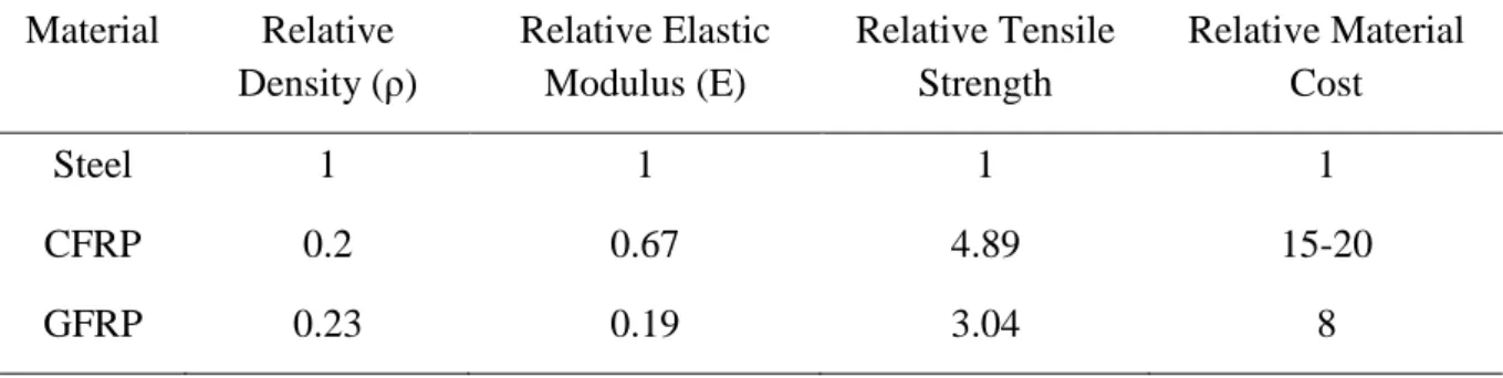
In Table 2.1, the properties of carbon fiber reinforced plastic (CFRP) and glass fiber reinforced plastic (GFRP) are compared relative to the steel. The values in the table are not real values, instead they are representative values for comparison.
Table 2.1. Representative costs of FRPs relative to the generic steel (Mallick, 2010, p.19)
Material Relative Density (ρ) Relative Elastic Modulus (E) Relative Tensile Strength Relative Material Cost Steel 1 1 1 1 CFRP 0.2 0.67 4.89 15-20 GFRP 0.23 0.19 3.04 8
State-of-the-Art 7
As can be seen in the Table 2.1, the continuous fiber composites have higher specific strength comparison to steel. Besides, the density of the FRPs is only the 20% of the steel’s density which is a great advantage for weight reduction. On the other hand, the cost of the FRPs is at least 8 times higher than the cost of the steel.
2.1.2 Mechanical Property Comparison between Woven Composites and Unidirectional Composites
The choice of reinforcement is a major step in the design of composites. As mentioned in the previous section, the two common fiber reinforcements are unidirectional and weave fabrics. The unidirectional fiber reinforcement consists of a sheet of non-undulated, parallel aligned fibers only one single direction. UD fiber layers have the maximum possible stiffness in the direction of the fiber alignment which is longitudinal direction, whereas very low stiffness in the transverse direction.
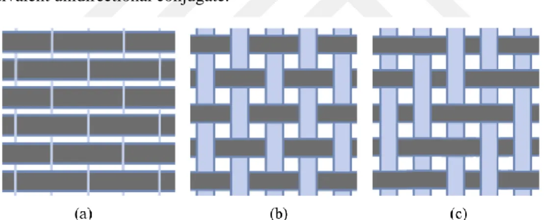
Woven fabrics consists of weaved fiber tows that are aligned both in longitudinal and transverse directions (Figure 2.3). Although that provides with stiffness in two directions, due to the undulation of the fiber tows, the maximum possible stiffness of woven composites is lower than their equivalent unidirectional conjugate.
Figure 2.3. Continuous fiber reinforcements. a) Unidirectional. b) Plain weave fabric c) twill weave
fabric. Retrieved from (Cai et al., 2017, p.144).
Although the stiffness of woven fabric drops due to the undulation of its fibers, it can drape and cover the non-flat, curved surfaces much better than unidirectional fabric (Harris, 1998, p.56). Other advantages of woven fabric composites are low effort manufacturability and good impact resistance.
Naik reports that the static load limit to initiate damage is higher for woven fabric composites than cross-ply unidirectional composites (Naik & Nemani, 2001, p.167).
Lastly, according to Pein woven fabric composites have higher weight specific energy absorption capacity during bearing failure than UD composites (as cited in Bergmann &
State-of-the-Art 8
Heimbs, 2017). In Figure 2.4, Bergmann’s pin pull-though test can be seen. As the pin is pulled, only the material in contact with the pin is destroyed. Therefore, the woven composite absorbs impact energy as the pin moves forward. In Figure 2.4, the area under the force-displacement curve represents the absorbed energy.
Figure 2.4. Bergmann’s pin pull-through test. Reprinted from (Bergmann & Heimbs, 2014, p. 2-4).
2.1.3 Composites in Automotive Applications
According to Kaw (2006, p.39), the weight of the composite parts in an automobile is only 8% of the total weight of the vehicle. In the automotive applications mainly, short E-glass fiber reinforced polymer matrix composites (PMC) are used. The short fiber E-Glass is preferred because of its low cost and suitability for mass production with injection molding and compression molding (Mallick, 2010, p.18). Some thermoplastic PMC automotive parts are: inner door panels, bumper beams and seat backs (Mallick, 2010, p.18). The thermoplastics used at these components are polypropylene (PP), Polyamide-6 and polyamide 6, 6. The common used thermoset PMCs in automotive industry are sheet molding compounds (SMCs). Its structure is random-oriented discontinuous E-Glass fibers inside a polyester or vinyl ester resin. Some SMC automotive parts are door and roof frames, hoods and radiator support (Mallick, 2010, p.18). The advantages of making leaf springs from composite material are unlikeliness of catastrophic failure, ride comfort and longer fatigue life (Kaw, 2006, p.39).
Failure Modes of Woven Fabric Reinforced Composites
The Failure of FRPs is a highly complex phenomenon since it is a combination of simultaneous cracking, bending and deforming of its building elements (reinforcement and matrix). In addition to the type and volume fraction of the components, the weave pattern of the fibers also plays a very crucial role. On the top of it, drilled and bolted composites show much more complex behavior than non-drilled composites. In this section, the failure modes of woven fabric reinforced composites are covered.
The failure of composites can be basically classified as inter-laminar failure, intra-laminar failure and bearing failure.
State-of-the-Art 9
2.2.1 Inter- and Intralaminar failures
The inter-laminar failure is detachment of the plies from each other. This failure is also referred to as delamination failure (Figure 2.5). In delamination failure, mainly the matrix falters and the plies of the composite laminate detach from each other, the fibers do not undergo any failure.
Figure 2.5. Delamination of the composite plies. Retrieved from (Schraa, 2016, p.28).
Intra-laminar failure stands for the cracks that occur within one or multiple plies of the laminate. At UD composites, intra-laminar cracks might tear the ply either between the fibers or perpendicular to fibers by breaking them apart (Figure 2.6). At woven composites, intra-laminar ply failure grows by destroying the fiber tows.
Figure 2.6. Intra-laminar cracks at PWTC. Retrieved from (Donadon et al., 2007, p. 1598).
The failure mechanisms of plain and satin weave composites under compression are kink band formation and delamination. The sets of compressively broken fibers are called kink bands (Figure 2.7). For higher fiber waviness, kink band formation is more likely. In other words, the strength of textile composite drops as the waviness of the fiber tows elevates (Cox & Flanagan, 1997, p.3-5).
State-of-the-Art 10
Figure 2.7. Kink bands that occur under compression. (A) Retrieved from Plymouth University
teaching support materials (Summerscales, 2017) (B): Retrieved from (Garland et al., 2001, p.2462)
As the fiber architecture of the woven composites include waviness and crimp of fibers in 3D, their failure modes are more complicated than unidirectional composites. The tow waviness (undulations) of woven fabric (Figure 2.8), results in stiffness reduction in in-plane directions and additional failure mechanisms that are not observed at UD composites.
Figure 2.8. Microstructure of a PWTC. The undulation of the fiber tows (A). Repetitive unit cell of a
plain weave textile composite (B). Retrieved from (Adumitroaie & Barbero, 2012, p.4).
2.2.2 Bearing at Composites Failure
Drilling, weakens the composites drastically since it violates the continuity of the fibers and creates notch effect. As the main load carrying component is the reinforcement fiber, the damage on the fiber tows results in serious stiffness and strength reduction of the composite. Therefore, the strength of open hole composite coupon (drilled composite) is much lower than non-drilled composites coupon.
Four principle failure modes of fastened composites (filled hole composite by pin or bolt) are net-tension, shear-out, cleavage and bearing failure (Figure 2.9).
(A) (B)
State-of-the-Art 11
Figure 2.9. Bearing failure modes at drilled and fastened composites. Retrieved from (Pakdil et al.,
2011, p.124)
The bolted composites fail at the bearing area by local compressive stresses in front of the bolt (Bergmann & Heimbs, 2017, p.300). According to the Farley and Jones (1992), the failure mechanisms of composite at drilled bearing area are: crushing characteristics by bolt are transverse shearing, laminate bending, brittle fracturing and local buckling (Figure 2.10).
Figure 2.10. Crush characteristics of the composite under pin compression (Bergmann & Heimbs,
p.300)
For safety concerns, energy absorber materials are used in passenger cars, trains and airplanes. These absorbers overtake the impact energy so that high forces and accelerations on the passengers are prevented. Composites is a type of energy absorber material.
Under bearing mode failure (Figure 2.9) fastened composite acts as a good impact energy absorber. When the bolt is pulled through the length of the composite, it shows a relatively constant rate of progressive failure. As the bolt pulled through the composite, it crushes the fibers bundles and the matrix sequentially along the way. This allows for absorption of a high amount of energy. Therefore, bearing mode failure of composites can be used as high weight specific energy absorption (SEA) materials for the above-mentioned purposes. Under progressive crushing, woven FRP absorbs more energy than unidirectional FRP according to Kim et al. (2009).
State-of-the-Art 12
2.2.3 Bearing Response of Composite under Compression by Pin
The material properties of a drilled material are lower than of a non-drilled (unnotched) material of the same kind. The drilled but not fastened specimen is called an open hole (notched) specimen. An open hole specimen fastened with a pin or bolt is called filled hole specimen (Figure 2.11). The response of bearing under compression of a pin or bolt can be called as bearing properties which are fundamentally lower than unnotched specimen configuration.
Figure 2.11. Specimen configurations. Reprinted from (Esp, 2017, p.28)
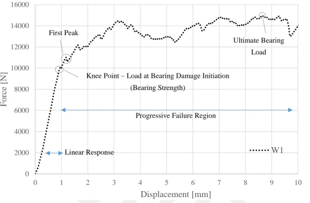
During the pin pull-through tests, the bearing region of the composite is compressed by the pin. As the pin moves forward, it opens its way by crushing the composite. The output of pin pull-through tests is force-displacement plots. The obtained plots are evaluated in terms of three parameters: stiffness, ultimate load bearing capacity of the bearing and bearing strength. In the Figure 2.12, a sample force-displacement curve of pin pull-through test of reference specimen W1 is shown. In this work, the pin pull-through force-displacement curves are investigated for stiffness, bearing strength and ultimate load bearing capacity.
State-of-the-Art 13
Figure 2.12. The transition from elastic to plastic response of reference specimen W1
The stiffness corresponds to the slope of the linear region of the force-displacement curve. According to Xiao (2015), the bearing strength (or damage initiation) value can be taken at 4%-hole displacement value (p.1024). The designed test system in this work is a customized test concept that represents a specific loading condition of a Mercedes Truck component. Therefore, a standard procedure cannot be followed to determine the bearing strength as Xiao suggests. The first drastic load drop is named as knee point. The knee point is considered as the damage initiation point which is the starting point of the non-linear bearing response. In the figure, the elastic response can be seen up to 1mm hole displacement. After the knee point, the scattered region is the non-elastic response. During the non-elastic response, the composite undergoes permanent damage and its stiffness drops. Despite the stiffness drop, the bearing can still carry load after the failure. The ultimate load capacity of the bearing is observed at the progressive failure region of the curve.
The bearing strength cannot be obtained from force displacement curve. Therefore, it should be calculated to stress-strain plot for calculation of bearing strength and elastic modulus. To determine the effective elastic properties at the bearing area, first the force-displacement curves of reference laminates should be converted to stress-strain curves, and then from the linear region of the obtained stress-strain curve, the elastic constant in pin movement direction should be calculated. 0 2000 4000 6000 8000 10000 12000 14000 16000 0 1 2 3 4 5 6 7 8 9 10 F or ce [ N ] Displacement [mm] W1 Ultimate Bearing Load First Peak Point
Knee Point – Load at Bearing Damage Initiation (Bearing Strength)
Progressive Failure Region
State-of-the-Art 14
According to Karakuzu et al. (2008, p.4), bearing stress at one of the two parallel pin-loaded holes is
𝜎 =
𝐹2 . 𝐷 . 𝑡
Equation 2.1
where σ is the bearing stress at each hole, F is the applied load, t is the thickness of the laminate and D is the diameter of the hole. According to Gay et al. (2014, p.140) and Liu et al. (2014, p.967) bearing strain for two parallel pin-loaded holes is
𝜀 =
𝛿𝐷
Equation 2.2
where ε is the bearing strain and 𝛿is the bolt displacement.
Multi-Material Design and Hybridization
For a robust hybrid structure, the strength of contact surfaces between structural elements is crucial. The strength of interface between hybrid components can be enhanced by modifying the contact surface. Some contact surface modification alternatives are customized contact zone by intrinsic hybridization, surface structuring the joint surface and roughening of the contact surface.
2.3.1 Intrinsic Hybridization
One method to produce multi-material hybrid parts is intrinsic hybridization. Intrinsic hybridization is a production method that the hybrid components are joined to each other during the production of one of its components.
For example, over molding a thermoplastic onto a metal with injection molding process is an intrinsic hybridization. Instead of producing the thermoplastic and metal separately, and then joining the two components in another production step, by intrinsic hybridization method the hybrid component can be produced in one single step. Intrinsic hybridization can also be implemented in resin transfer molding (RTM), integral tube blow molding, rotational molding and automated fiber placement processes. (Koch et al. 2016, p.239). In short, by consolidation of production steps, time and money for production of the hybrid component can be reduced. Examples for customized contact zones are curved and inclined joining zones (Figure 2.13). Such joining zones improves the joint strength by reducing the stress peaks on the joint interfaces. The hybridization methods can be combined to superimpose their effects (Kießling et al. 2016, p.4).
State-of-the-Art 15
Figure 2.13. Customized contact zones: (A) Inclined contact zone and (B) curved contact zone and,
(C) curved and inclined contact zones combined. (A) and (B) retrieved from (Kießling et al. 2016, p.4).
2.3.2 Surface Structuring and Surface Roughness
The customized contact surface between hybrid components (Ch.2.3.1) provides mechanical interlocking in macroscale. To further improve the strength of the contact surface, a method called surface structuring can be used. Surface structuring is a method to enhance the surface adhesion between two surfaces. Surface structures are geometric patterns that are shaped on a contact surface(Ucsnik et al., 2010). The surface structures provides mechanical interlocking by penetrating into to surface of the other contact pair. The surface structures can be pins, grooves or walls. They act as mechanical undercuts and improves the mechanical interlocking between metal and composite
Lucchetta et al. (2011) molded thermoplastic polymer onto an aluminum using injection over-molding process. They showed that the joint strength between the metal and the thermoplastic polymer is higher when metal’s surface is rougher.
2.3.3 Injection Molding for Hybridization
The main methods to manufacture plastic products are blow molding, extrusion molding, injection molding and thermoforming. Blow molding produces hollow parts, where extrusion molding is used for making fixed profile parts. In thermoforming, a plastic sheet is pressed in a mold. In injection molding, the plastic is pushed to fill a cavity to shape the plastic part. Very complex plastic parts can be produced with injection molding. Besides, injection molding is very suitable for serial production. In the long run, injection molding is very suitable to produce low cost plastic parts. More importantly, injection molding process is used widely to make hybrid parts. One of the hybrid component can be placed inside the injection mold cavity, then the plastic can be injected to surround the hybrid component. The mechanical interlocking is formed between hybrid components. Complex hybrid parts can be produced with this method. This hybridization method is exploited by Pohl & Stommel in their metal-polymer hybrid connection (2017). In addition, injection molding is used in making of metal-polymer front end of Ford Focus and Audi A6 Avant (Lanxess Corporation, 2005).
State-of-the-Art 16
2.3.4 Polymer to Metal Surface Adhesion
To join dissimilar materials to each other, a sticky adhesive material can be applied to the interface. Adhesives is not covered in this chapter since it is not used in this thesis work. Another method is direct surface adhesion between the dissimilar materials. Typically, direct surface adhesion between two dissimilar material (e.g. metal and thermoplastic) is not strong. The three main alternatives to improve the polymer to metal direct adhesion according to Grujicic et al. (2008, p.363) are micro scale interlocking, pre-coating of the metal and chemical modification of the polymer. However, among above mentioned adhesion promoters only the micro-scale polymer-to-metal mechanical interlocking approach was used. The molten plastic infiltrates into the micro scale-roughness features on the metal insert. This infiltration provides with mechanical interlocking between metal and polymer.
The four process parameters that affect the strength of direct adhesion between polymer and metal are the temperature of the metal insert, linear velocity of the injection screw, thickness of the polymer and packing pressure (Ramani & Moriarty, 1998).
In their investigation Ramani and Moriarty (1998) found that the temperature of the metal inserts to be the most critical process parameter. They suggest the optimum temperature for metal as 210 o C degree during the plastic to metal over-molding process. Ramani also shows that if the metal is at room temperature during the injection, the plastic freezes before being able to infiltrate into the micro-roughness features of on the surface of the metal.
Finite Element Modeling at Abaqus Environment
Since experimental testing is often a very cost-intensive procedure, the engineers prefer to solve the mathematical description of the engineering problems. The partial differential equations (PDEs) at the mathematical description of the real-life problems can be solved with analytical or numerical models. Although analytical solutions are very accurate, it is difficult or mostly impossible to solve the PDEs of a problem analytically. On the contrary, the numerical methods offer an effort-accuracy friendly solution for engineering problems, therefore numerical methods are preferred by engineers.
Finite Element Method (FEM) is the most popular numerical method that is used by engineers. In Finite Element Analysis (FEA), the geometry (or the solution space) is discretized in smaller volumes that are also called mesh elements. PDEs are solved for each mesh element. The FEM solution to the PDEs approximates the real solution.
State-of-the-Art 17
In this thesis, the commercial FEA software Abaqus is used. It allows for simulation of the composites structures. The composites can be modeled in Abaqus environment in different scales according to the purpose of the analysis. Simulia/Abaqus Documentation suggests the following approaches for FE modeling of the composites (Smith, 2009).
Microscopic Modeling: Both the reinforcement and matrix are modeled and meshed as individual solid bodies. In this method, reinforcement – matrix interface can be modeled. Macroscopic Modeling: The composite lamina is modeled as a single anisotropic solid
body.
Mixed Modeling: The layers of composites are modeled forming the composite laminate. Most common and Abaqus offers standard tools for this method (e.g. Composite layup) Sub-modeling: A certain area of an already existing model is modeled in a ‘sub-model’ in
more detail (e.g. modeling stress peaks at the tip of the reinforcement).
FE Modeling of Plain Weave Textile Composite
Composite materials consist of at least two constituents. To perfectly model a composite structure in FE environment, it is necessary to geometrically model and characterize the material properties of each constituent. In an ideal model micromechanics of the composite should be represented. For this, fibers and the matrix of the composite should be modeled and meshed separately. The contact interaction between the fibers and the matrix should be defined. However, FE modeling of PWTC are often simplified since micromechanical modeling requires high effort to model the geometry of the inter-weaved fiber tows and their interaction with the matrix (Knight, 2008, p.3).
One simplification method which is not used in this thesis, is to model plain and satin weave fabric plies as two unidirectional plies at [0o/90o] directions. In this configuration, one woven composite ply is represented with two layer of mesh elements. One layer of mesh elements is modeled as an UD ply which is aligned in the warp direction and the other layer of mesh elements is modeled also as an UD ply which is aligned in the weft direction. Both layers of mesh elements should be assigned to have half of the thickness of the actual woven composite ply (Knight, 2008).
State-of-the-Art 18
In another simplification method, which is used in this work, every composite layer is represented with one layer of mesh element at thickness. The thickness of mesh elements should have the same thickness as composite plies. The characterized material properties of the composite should be assigned to the mesh elements. In this approach, the mesh elements represent the fibers both in warp and weft directions. Therefore, the corresponding material property of the composite should be assigned to principal directions of the mesh elements. It can be assumed that the properties of the composite are the same in warp and weft directions for further simplification (E1=E2).
Design of Composite Specimens 19
3
Design of Composite Specimens
The Real Case Scenario – Truck Component
The design of the composite specimens was realized according to the connection area of current Cab rear suspension bracket to the chassis. The component was produced from steel and would like to be replaced to composite material within the scope of cost & weight reduction.
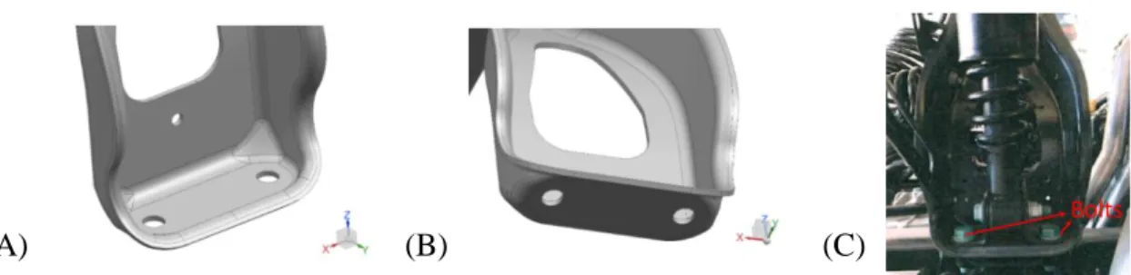
The Mercedes Benz-Truck component of interest is a bracket (Figure 3.1) at rear cab suspension unit. This bracket was fastened to the chassis with two M18 bolts.
Figure 3.1. The rear cab suspension bracket
The bracket is in U shape, has two flat surfaces at its both ends, these two flat surfaces (Figure 3.1) sits on the chassis. These flat surfaces of the bracket are fastened to chassis with two M18 bolts at each side (Figure 3.2). The bracket is part of the rear cabin suspension unit. The steel bracket and the air springs damp together the impacts on the cabin.
Design of Composite Specimens 20
Figure 3.2. The flat surface of the bracket that sits on the chassis (A & B) and bracket is connected to
the below connection elements with two M18 bolts (C).
The Concepts used at the Design of Inserts
Two joining concepts from literature inspired the insert design at this thesis. As shown in Figure 3.3, the first concept is the hybrid connection element of Pohl & Stommel (2017). And the second concept is the fastener inserts that can be placed between the layers of the composite (BigHead® Bonding Fasteners, 2015). In Figure 3.5., implementation of a Bighead® insert in composite can be seen.
The concept of Pohl and Stommel (2017) is based on mechanical interlocking of the joint partners to each other. The joining components are interlocked to each other with the help of inclined contact zones which creates bumps as in the Figure 3.4. In his specimens, he joins a rectangular aluminum sheet and CFRP to each other (Figure 3.3).
Figure 3.3. Hybrid metal-composite connection element with a polymeric material in the interface
(Pohl & Stommel, 2017).
There are two problems regarding joining the composites with mechanical fasteners (e.g. bolt). First is that drilling weakens the composite, and second is tapping of composite is not perfectly possible. Bighead® inserts offers remedy for these two issues.
Some type of the Bighead® inserts has a tapped bolt socket (Figure 3.5). The Bighead insert is placed between the layers of the laminate before curing of the composite. By doing so, the tapped bolt socket is placed at the composite. In addition, the reinforcement fibers can be layed around the socket collar during the production of the composite. In short, by using Bighead® inserts, drilling and weakening of the composite can be avoided. Besides, the metal sheet of the BigHead® insert provides with additional contact and reinforcement between fastener and the composite (Figure 3.5).
Design of Composite Specimens 21
Figure 3.4. Inclined contact surfaces (bumps) (Pohl & Stommel, 2017).
Figure 3.5. A commercial Bighead® Insert (A) with a pre-defined bolt socket and Bighead® insert
embedded in CFRP (B). Images retrieved from (BigHead® Bonding Fasteners, 2015).
The above mentioned three concepts (curved contact surface, pre-defined, tapped bolt and directing the fibers around socket collar) were exploited at the inserts of this thesis work (Table 3.1). As can be seen in the following Figure 3.6, in this work the inclined contact surface were inspired from Pohl’s design.
Figure 3.6. Curved contact surface designed at this work (A) and curved contact surface at Pohl &
Stommel’s design (B).
The inserts of this thesis have bolt sockets (Figure 3.7) similar to BigHead® inserts. However, in this thesis the sockets were not tapped for two reasons. First, the material of the insert (thermoplastic) is not suitable for tapping. Second, tapped hole is not necessary since pinned
(A) (B)
Design of Composite Specimens 22
connection is used in this work. Pinned joint was used to be able to observe crush of the composite and to avoid the pretension on the composite by tightening of the nut.
Figure 3.7. The pin socket design of this work
In the scope of this work, three types of inserts were developed. Namely: metal insert, polymer insert and metal-polymer hybrid insert (Figure 3.8, Figure 3.9). The concepts that are used in their design is listed in the Table 3.1.
Table 3.1. The concepts used at the designed inserts
Insert Type Collar Buried Inside the composite
Curved contact surface
Metal Insert No Yes Yes
Polymer insert Yes Yes Yes
Metal-polymer insert
Yes Yes Yes
Figure 3.8. The three types of designed inserts. (Left) Metal Insert, (Middle) Polymer Insert, (Right)
Metal-Polymer Insert
The metal-polymer hybrid insert consist of two materials, metal core and a thermoplastic material covering the core metal.
Design of Composite Specimens 23
Figure 3.9. Section of the metal-polymer hybrid insert.
Design of Laminate and Inserts
The main load bearing constituent of an FRP is the reinforcement fiber. If the composite is drilled to create a bolt hole, the continuity of the fibers is violated. The drilled fibers are not able to bear load, therefore drilling weakens the strength and stiffness of the composite. One method to avoid drilling the composite is to create the bolt hole during the production of the composite. To avoid drilling, inserts with bolt hole socket (as in Bighead® concept) can be used (Figure 3.7). The fibers can be layed around the socket collar so that the continuity of the fibers is not violated. In addition, the insert provides with a socket to fasten the bolt. The inserts in this thesis were designed accordingly.
All the designed inserts consist of two bearing holes on the both sides and a rod connecting the two bearings. The connection rod transfers the load to the middle of the insert from the bearings. In other words, the load at the bearings is reduced by spreading the total load along the insert.
The Concepts used at the Design of Inserts
3.4.1 Metal Insert
The thickness of the metal was chosen to be 1.5mm. According to pull-out experiments on Bighead® inserts, the thickness variation of the insert plate from 1mm to 2mm provided 54% improvement of load bearing capacity whereas variation from 1mm to 3mm provided only 58% improvement in load bearing capacity (Gebhardt et al. 2015, p. 513). For thicker insert plates delamination failure risk increases, therefore the load bearing capacity does not increase linearly. Thus, 1.5mm insert thickness seem to be a good compromise between strength and weight. In addition, Gebhardt et al. (2015, p.512) showed that thicker plate leads to crack initiations at carbon fiber due to steeper bend angle of carbon fabric.
Design of Composite Specimens 24
The metal insert has two sockets for M18 pin or bolt, but it does not have a collar to direct the fiber. Metal insert is a sheet part, which has constant thickness at all points. Therefore, the socket is in plane with other areas of the metal insert.
Figure 3.10. The sheet metal insert with plain bearing socket
a
Figure 3.11. The cross-section dimensions of the composite laminate with metal insert
Figure 3.12. The cross-section of the composite laminate with metal insert
Design of Composite Specimens 25
3.4.2 Polymer Insert
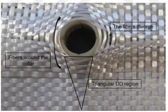
The polymer insert has two untapped sockets for M18 pin or bolt. The polymer insert is not a sheet part, it has non-constant thickness. Besides, its socket has collar. The purpose of the collar is to create a guide to direct the fibers around it. So that during the production of the composite laminate, the fibers can be simply widened (Figure 3.13). Hence direct contact between rod and GFRP is avoided by this way.
Figure 3.14. Tows of glass fibers are directed around the collar
As can be seen in the Figure 3.14, the fibers diverge from each other a socket collar region. This disrupts the distance between the glass fiber tows of the plain fabric and creates triangular unidirectional fiber regions (Figure 3.14).
Figure 3.15. Change of distance between fiber tows due to collar
The top and bottom surfaces of the insert collar was designed to be at the same plane. The reason of this design is to avoid out of plane geometry protrusions form the surface of the
Design of Composite Specimens 26
laminate. This should be ensured because the bracket surfaces sit on the chassis, so that bottom of the bracket should be flat.
Figure 3.16. Cross sectional dimensions of the composite laminate with metal-polymer insert
Figure 3.17. Cross-section of the composite laminate with polymer insert
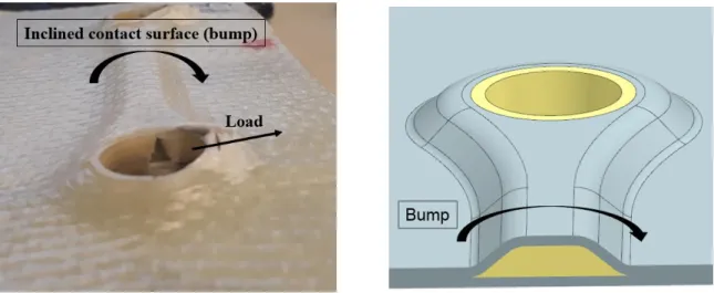
The contact surface between the polymer and FRP can be designed in a way that it provides mechanical interlocking between polymer and FRP as already studied by Pohl & Stommel. In their study, an inclined contact surface increases the interlocking between GFRP and polymer Pohl & Stommel, 2017, p.4). The same inclined contact zone concept is implemented in this thesis work. As in Figure 3.18, the contact between embedded polymer insert and the composite is also inclined which creates a so-called bump. This inclined zone carries loads in perpendicular direction to its bump.
Design of Composite Specimens 27
3.4.3 Metal-Polymer Insert
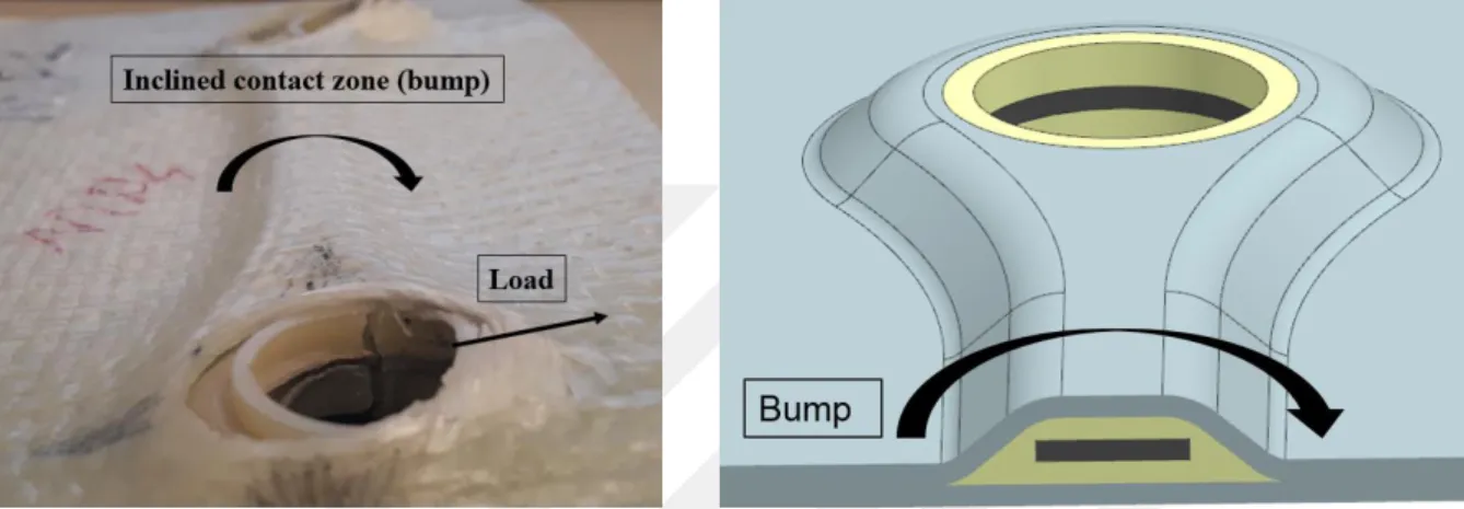
The metal inserts that was explained in the chapter 3.3.1 was used at the metal-polymer hybrid inserts. The idea of covering the metal with a polymeric material is to avoid the direct contact between the edges of metal and GFRP, so that the sharp edges of metal would not damage the fibers. Besides that, the curvature angle of fibers should not be sharp. Otherwise, fibers would break, and their load bearing capacity would diminish. To smoothly direct the fibers, the side of the polymer was designed as in the Figure 3.18. However, this design brings a serious problem. The edges of the metal insert are very sharp. These sharp edges might lead to delamination of the composite.
Figure 3.19. Dimensions of the metal-polymer insert
Figure 3.20. Cross-section dimensions of the composite laminate with metal-polymer insert
Figure 3.21. The cross-section of the composite laminate with metal-polymer insert
The total thickness of the specimen is 7.5mm at the insert area (Figure 3.19).
The polymeric material was injected around the metal insert using ‘Arburg Allrounder 270 S 400 – 100’ injection molding machine at the machine hall of LKT (Lehrstuhl für Kunststofftechnik) of TU Dortmund.
Design of Composite Specimens 28
The sharp edges (Figure 3.22) of the polymer might be disadvantageous because it might intensify the delamination by cutting and splitting the matrix between the composite plies.
Figure 3.22. Sharp edges of the polymer and metal-polymer inserts.
Design of Composite Specimens 29
Laminate Design
The composite specimens that are designed in this thesis represents the flat surfaces of the bracket as can be seen in the (Figure 3.23). Therefore, the diameter of the holes (19mm) and the distance between the holes (125mm) is predetermined (Figure 3.24).
Figure 3.24. Flat surface of the cab rear suspension bracket and the designed specimen
Figure 3.25. Dimensions of the composite specimen
As reinforcement material glass fiber is chosen due to its cost and durability advantage. As a rule-of-thumb, elongation at failure for carbon and E-glass is 1.5% and 4.9% subsequently (Mallick, 2010, p.17). Glass material was chosen because its cost is lower, and it is more elastic than carbon. Since the truck component is a part of suspension unit, it deforms recurrently under road conditions, so the composite bracket should be able to deform without failure up to a certain extent.
As the form of fiber, bi-directional (0o, 90o) plain woven fabric was used (Figure 3.25). Every
ply was stacked at same orientation which is 0, 90o with respect to the edges of the lamina. In
total, 10 layers of glass fabrics were stacked. The thickness of each plain weave glass fabric ply is 0.3 mm. Therefore, the thickness of composite laminates is in total 3mm.
Design of Composite Specimens 30
Figure 3.26. E-glass plain weave fabric
In total four types of specimens were designed: the reference specimen, specimen with metal insert, specimen with polymer insert and specimen with metal-polymer insert (Table 3.2). All types of inserts create a bump at the top surface of the laminate. This bump provides extra interlocking between the composite and the inserts.
Table 3.2. The four types of designed specimens
Abbreviation Insert Holes
W No Drilled
M Metal Insert Drilled
P Polymer Insert Not drilled
Production of Inserts and Specimens 31
4
Production of Inserts and Specimens
In the production of designed inserts and the composite laminates, cost-friendly and suitable methods for serial production were pursued. As in the future steps of this research, the inserts are desired to be used in a real world automotive applications, cost and serial production suitability are important concerns.
As a general overview, the used production methods are laser cutting, injection molding and hand lamination. The metal insert was produced by laser cutting process. The polymer insert was produced by plastic injection molding process. And the composite laminates were produced by hand lamination process. The produced three types of inserts can be seen in the Figure 4.1.
Figure 4.1. Pictures of produced inserts. (Top) Metal insert, (middle) polymer insert, (Bottom)
Metal-polymer hybrid material insert
Two FRP production processes are Hand lamination and resin transfer molding. Hand lamination is the most manual FRP production method. The placement of the fibers, application of the resin, and the placement of the un-cured FRP in a vacuum bag performed manually by hand. On the other hand, resin transfer molding machine automates the injection and the curing
Production of Inserts and Specimens 32
of the resin, only leaves the placement of the fibers to the operator. In fact, the placement of the fibers in the mold can be automated with an automated fiber placement (AFP) machine.
Production of Metal Inserts with Laser Cutting
For this thesis work, 1.5mm thick metal inserts are produced with laser cutting process. The metal inserts were cut from steel sheet plates using Trumpf LASERCELL TLC 1005 machine at IUL (Institute für Umformtechnik- und Leichtbau) of TU Dortmund (Figure 4.2). The edges of the produced inserts are not sharp which is advantageous since the edges of the metal insert would not create severe notch effect on the FRP.
Figure 4.2. (A) Laser Cutting Machine, Retrieved from Kistner Machine Tools (2001, p.11) and (B)
production defect during laser cutting
The only disadvantage of laser cutting is local over molten spot defect which is shown in Figure 4.2. The laser nozzle stays without moving at its starting position for too long, therefore extra material was removed from the steel at a certain spot.
Production of Polymer Insert with Injection Molding
Plastic injection molding process was used for production of polymer insert and metal-polymer insert. In addition to its applicability to serial production, another advantage of injection molding is its ability to produce complex geometries. Considering the complex geometry of the designed polymer insert, injection molding might be the only method to produce the plastic insert and cover the metal insert with polymer. The Arburg 270 S 400-100 machine (Figure 4.3) was used for injection of the polymer around the metal insert.
Production of Inserts and Specimens 33
Figure 4.3. Injection Molding Machine - Arburg 270 S. Retrieved from (Arburg GmbH, 2015).
The injection tool was machined with CNC process. Aluminum mold plates were chosen because the machinability of aluminum is high. The mold plates can be seen in Figure 4.4.
Figure 4.4. Injection molding tools (Mold plates)
The maximum stroke volume of the Arburg 270 S is 49 cm3 (Arburg GmbH, 2015). This volume corresponds to the amount of polymer that the injection machine can inject from the nozzle at one cycle. The total volume of polymer volume of the cavity and the sprue is 11 cm3. Although
the stroke volume capacity of the machine is far more than the polymer’s volume, only one cavity was machined on the die to ensure the filling of the small features (the thin edges) of the polymer’s geometry.
Sprue gate was used to inject the polymer into cavity. As a rule of thumb, the sprue gate should have circular cross section. It is suggested to place the sprue gate at the thickest section of the
Production of Inserts and Specimens 34
molded part (Menges et al., 2001, p.205,206). The diameter of the sprue is suggested to be 1 mm larger than the section thickness (smax) (7.5 mm for our part) as in the formula (Menges et
al., 2001, p.205, 206):
𝑑 > 𝑠𝑚𝑎𝑥 + 1 𝑚𝑚 Equation 4.1
where smax is the maximum section thickness and the d is the sprue diameter. The thickest
section (smax) of our designed plastic part is 7.5 mm. Therefore, the sprue diameter was chosen
to be 9mm (>7.5mm + 1mm) according to Equation 4.1 with half millimeter extra.
The only disadvantage of the sprue gate is at post-processing. The removal of the produced part from the injection tool is troublesome. In the production of the inserts that are designed in this work, the sprue was often stuck in the sprue bushing, therefore it had to be pulled out with the help of a gripper.
In this work, pin shaped surface structures were placed on the surface of polymer insert (Figure 4.5). These pins create a mechanical interlocking in milimeter scale between polymer and FRP by penetrating into the matrix of the FRP. The same injection tools were used to produce both the polymer insert and the metal-polymer insert. The process steps were explained in the following two sections.
Figure 4.5. (A) Surface structure cavities on the mold plate and (B) the pin shaped surface structures
on the polymer insert
4.2.1 Production Steps of Polymer Insert
The polymeric material is Vestamid HT plus M1033 – Polyamid (PA) 66 with 33% glass fiber content of its volume. The recommended melt temperature of Vestamid HT plus PA66 - M1033 during injection molding is 315 o C and the recommended tool temperature interval is 140-180
o C(Kuhmann, 2012, p.12). The mold temperature was chosen to be biggest value which is 180 o C to prevent freezing of the polymer before filling all the small features i.e. the tip of the
polymer.
First, according to the Vestamid HT Plus Processing Datasheet for injection molding, the polymer granules were heated for 4 hours in the hopper to drop the moisture content below 0.06% by weight (Kuhmann, 2012, p.2).
Production of Inserts and Specimens 35
Figure 4.6. Plastic Injection machine
Then, up to 200 o Cheated mold plates were closed. The polymeric material was injected from
nozzle to the cavity. After the injection and the packing, the molds open and the part is removed from the cavity manually.
4.2.2 Production Steps of Metal-Polymer Insert
The same drying, injection, packing and removal processes were performed as in the production of the polymer insert. The only difference of metal-polymer insert is the placement of the metal inserts to the cavity before closing the mold and injection of the thermoplastic.
Before the placement in the mold cavity, the metal inserts were cleaned with a cleaning agent in an Ultrasonic Vibration machine (Figure 4.7) to remove the residual materials (e.g. dust, dirt, and burr) on the metal surface. The cleaned metal inserts were heated up to 200 o C in an oven
and then placed in the cavity at the injection tool (Figure 4.8). After that, the molds are closed, and polymer is injected.
Figure 4.7. (A) Ultrasonic Vibration Machine and (B) Cleaning Agent.
To be able to place the metal insert in the mid plane of the cavity, support pins were machined on the injection tool (Figure 4.9). These pins hold the metal from top and bottom so that the