379
Improving
AWE
Accuracy Using Multipoint
Pad6
Approximat
ion
M. Celik, 0. Ocali, M. A.
Tan,
and A. Atalar
Dept.
of
Electrical and Electronics Engineering
Bilkent University
06533
Bilkent, Ankara, Turkey
Abstract- A new method is proposed for dominant pole-zero analysis of large linear circuits containing both lumped and distributed elements. This method is based on a multipoint Pad6 approximation. It finds a reduced or- der s-domain transfer function using a data set obtained by solving the circuit at only a few frequency points. The proposed method yields more accurate computation of transient and frequency responses with respect t o the AWE-type techniques.
I. INTRODUCTION
Asymptotic waveform evaluation (AWE) is an efficient technique that is used for dominant pole-zero approxi- mation [l] [2 ] . It employs a form of Pad6 approximation to approximate the behavior of the higher order linear circuit with a reduced order model. The first few terms of power series expansion of the reduced order transfer function are matched t o the moments and the Markov parameters of the actual circuit, which can be computed efficiently by a set of simple dc analyses. Actually the moments and the Markov parameters result from a Tay-
lor series expansion of the circuit response about s = 0 and l / s = 0, respectively. It is then obvious that the mo- ments convey information about the low-frequency char- acteristics of the circuit, while the Markov parameters can only represent the high-frequency behavior. How- ever, for some applications, specifically in RF and mi- crowave circuits, the mid-frequency range is more im- portant. Hence, we need t o make use of the information obtained from the mid-frequency characteristics of the circuit t o find a better approximation.
In this paper, we propose a new order reduction tech- nique that gives more accurate results with respect to the conventional AWE technique. In the proposed ap- proach, the circuit matrix is solved a few times in the fre- quency range under consideration. The derivatives of the network function with respect t o complex frequency are obtained efficiently from these the solutions. By using these derivatives a t different complex frequency points, a multipoint Pad6 approximation is performed in order t o obtain a reduced order s-domain network function. Poles and zeros (or poles and residues) can be found from this rational network function using standard techniques.
11. THE METHOD
Consider a linear system modeled by a set of linear alge- braic equations in the Laplace domain,
T(s)x = w (1)
where T is the system matrix, the vector x is the system response and the vector w is the system excitation. In general, the system matrix T is an arbitrary function of complex frequency s. Let the system output be any linear combination of the system response,
( 2 )
F = dTx. Using Cramer’s rule one can obtain
det T
F ( s ) = (3)
Our aim is to approximate the network function F ( s ) , regardless whether it is a rational or irrational function of s, with a rational function F ( s ) which has approximately the same frequency characteristics as the original circuit does. Let the approximate function be of the form
(4)
bo
+
b1s+
...
+
b , - d - l 1+
u1s+
...
+
uqs*F ( s ) =
Since there are 2q parameters t o compute in the re- duced model, we need 2q constraints from the actual circuit. In the AWE technique 2q unknowns are cal- culated by matching the first r moments and the first
( 2 q - r ) Markov parameters of the original circuit t o the
approximate rational function.
In this work, we propose a method which uses a data set obtained from the circuit to-construct the approximate s-domain rational function, F ( s ) . This data set contains the translated moments obtained a t different complex fre-
quency points. In the following, we present the evalua- tion of the translated moments and how t o match them to a rational function.
380
2.1.
Translated moments
equations.The system response X ( S ) in ( l ) , can be expanded in
Taylor series at s = SO as:
provided that X ( S ) is analytic a t s = SO. The coefficient
X k in (5) is called the vector of kth translated moments
and
The first translated moment vector is the solution of the circuit at s = S O ,
It can be easily shown that the higher order translated moments can be evaluated recursively as,
. .
r = l
where superscript ( r ) indicates the rth derivative with respect t o s evaluated a t s
=
SO. Since the LU factor- ization of T(s0) are known from the solution of the first translated moment vector, each higher order translated moment vector can be obtained only by one forward and back substitution (FBS).2.2. Multipoint moment matching
The translated moments m k ' s of the transfer function
are obtained from the translated moment vectors x k as,
Note that, the translated moments a t s =
SE
are complex conjugates of the translated moments a t s=
SO. We match the first q translated moments a t s = SO and theirconjugates t o a qth order rational function:
bo
+
bls+
...+
b q - 1 s q - l1
+
u1s+
...
+
U q S Q= mo
+
m l ( s - S O )+
...
+
m q - l ( s-
s 0 ) q - l+
h.0.t.= m g + m ; ( s - ~ S ; I ) + . . . + m i - l ( s - s ; ) ' - ' +h.o.t.
One can show that finding the coefficients of the rational function is equivalent t o solving the following set of linear
where k G O = 1
+
ci=l
UkSO k k - i bi = c P - l b k k - i iri = C i , i u k ( i ) s o,
i
= 1 , 2 , . . , q - 1 k = i k ( i ) S o 7 i = o , 1 , . . , ' ? - 1 and 6;=
1+
C i = i ; k ( S : ) '4;
=ci=i
U k(
i ) ( S : ) k - i , i = 1 , 2 ,..,
q - 1 bf =E',::
b k ( ! ) ( s G ) k - i , i = 0 , 1 , . . , q - 1Once the coefficients of the rational function are obtained from the above set, the poles and zeros (or poles and residues) can be found from the polynomials of the ra- tional function using standard techniques.
The one-point moment matching technique can be ex- tended t o the multipoint case as follows:
i-Select m frequency points on the s-domain.
ii-Calculate pi moments a t the ith frequency point for
i
=
1,..,
m , such thatELl
pi = q. With the addition of the conjugates of these q moments, the number of con- straints obtained from the circuit equals t o the number of unknowns in the reduced (qth) order s-domain net- work function.iii-Solve the system of 2q x 2q linear equations which is constructed by taking the first 2pi equations from the ith equation set for i = 1,
..,
m.As a summary, the coefficients of s-domain rational func- tion are found by solving a 2q x 2q linear equations sys-
tem. It corresponds to inversion of a real matrix of size 2q x 2q which has a complexity of O((2q)3). Although there exist some other algorithms of 0((2q)2) t o obtain the coefficients of the rational function [3], our experience suggests that the direct inversion of the real matrix yields better results than the methods mentioned in Ref. [ 3 ] , in terms of numerical accuracy.
2.3. Formulation
of
the Circuit Equations
Assume that the given circuit contains linear lumped components and linear subcircuits. The subcircuits may
38
1. exact
- - proposed method (1-p)
-
contain distributed components. By using Modified Nodal Analysis (MNA) formulation, the frequency domain re- sponse of the circuit can be computed from the matrix equation [4]
,
T(s)x = w (11)
or explicitly
I
JLkY
‘ L o ] ’
where G and C are matrices formed by the parametersof the lumped components,
V
is a vector containing the node voltages, and the currents of the inductors and the voltage sources, U is the vector of the values of the in- dependent sources,k
is the number of subcircuits, Diis the appropriate incidence matrix corresponding to the terminal currents of the zth subcircuit, Ii is the vector
of terminal currents and Yi is t h e admittance matrix of the zth subcircuit.
The derivatives of T evaluated a t s = SO are
and C 0 0
. . .
0 Yl1)(so)D1 0 0. . .
0 YP)(so)D2 0 0. . .
0. . .
0 Yr)(so)Dk 0 0. . .
0.
.
.
.
.
.
0 0 0. . .
0 Y(lf)(so)Dl 0 0. . .
0 YF)(so)D2 0 0. . .
0. . .
0.
.
. . . . Yr)(so)D~, 0 0 . . . 0 IThe derivatives of the admittance matrices of the sub- circuits are given in Ref. [4].
2.4.
Examples
A circuit which contains six of band-pass filters in par- allel is considered. It is composed of 20 transmission lines, 23 inductors, 32 capacitors and 26 resistors. The filters are switched by PIN diodes. Because of finite iso- lation of the PIN switches the active filter is loaded by
0 . exact - - proposed method (1-p) - proposed method (3-p) I .I
.
r
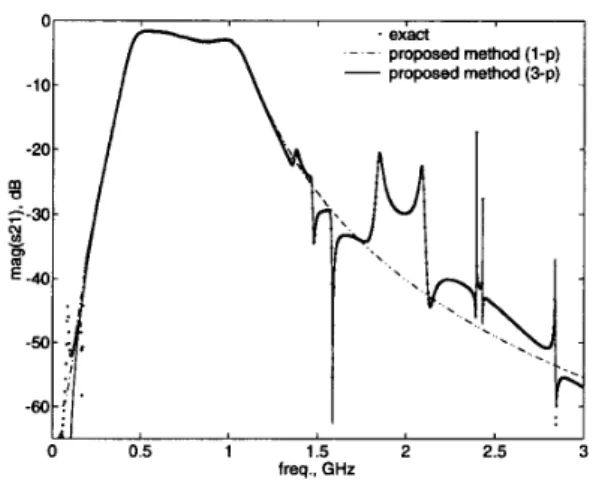
-6o-! I I I 0 0.5 1 1.5 2 2.5 freq.. GHzFig. 1. Frequency response (magnitude) of the band-pass filter circuit.
the other filters, hence the resulted frequency response is very complicated. The magnitude and phase of the frequency response found by the proposed method are shown in Figs. 1- 2 by solid lines. It is a 40th order ap- proximation with three-point moment matching (m=3, p2 = 13, p3 = 13). The frequency response obtained by solving the circuit a t 1000 frequency points, is shown by dots on the same figures. Even 1000 points may not be sufficient, because some sharp peaks in the graph may be missed as can be seen in the Fig. 1. Dot-dashed lines in those figures correspond t o a 10th order approximation with one-point moment matching (m=1, s1 = 0.65 GHz,
p l = 10). It approximates the pass-band of the filter suf-
ficiently well, but cannot catch the details for outside the SI = 0.65 GHz, ~2 = 1.65 GHz, ~3 = 2.5 GHz, p i = 14,
I
382
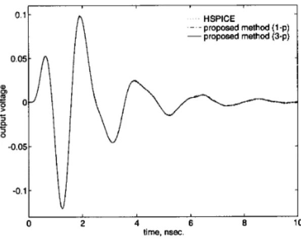
HSPICE - - proposed method (1-p) -proposed method (3-p) I I 0 2 4 6 8 10 time, nsec.Fig. 3. Step response of the band-pass filter circuit.
pass-band region. The step response of the filter circuit is computed by the new method for two different orders of approximations as indicated above. The results are shown in Fig. 3 along with the HSPICE result for com- parison. The one-point approximationis very close t o the actual response, while the three-point approximation is virtually indistinguishable from it.
The second example is a low-pass filter implemented with transmission lines. The exact frequency response of the filter is shown in Fig. 4. In the same figure, we also give
the 10th order AWE approximation. The step response of the circuit corresponding the 10th order AWE approx- imation is given in Fig. 5 together with the HSPICE re- sponse. As it is seen from Figs. 4- 5, the AWE method approximates the low-frequency characteristics of the cir- cuit very well, but it is not able to detect the repetitions of the frequency response and therefore the high fre- quency transients. However our method, using a three- point moment matching (m=3, SI = 4 GHz, s~ = 16 G H z , s ~ = 32 GHz, p l = 8, p:! = 10, p3 = 12), finds all
the details of the both responses (solid lines in Figs. 4- 5).
111. CONCLUSIONS
A new order reduction method for linear circuits has been presented. This method uses a multipoint Pad6 approximation t o find a reduced order s-domain network function. In other words, it computes approximate poles and zeros (or poles and residues) for the given circuit. The obtained poles are not necessarily low-frequency ap- proximations as it is the case in AWE. Consequently, while this method preserves the efficiency of AWE, it
Fig. 4. Frequency response of the low-pass filter circuit.
0.41
I‘
4 n HSPICE AWE_ _
- proposed method 0 0 0.2 0.4 0.6 0.8 1 1.2 1.4 time, nsec.Fig. 5. Step response of the low-pass filter circuit.
improves its accuracy.
REFERENCES
[l] L. T. Pillage and R. A. Rohrer “Asymptotic waveform evalu-
ation for timing analysis,” IEEE Trans. on Computer-Aided Design, vol. 9, pp. 352-366, April 1990.
[2] X. Huang, V. Raghavan, and R. A. Rohrer “AWEsim: A program for the efficient analysis of linear(ized) circuits,” in Tech. Digest IEEE Trans. Computer-Aided Design, pp. 534- 537, November 1990.
[3] K. Hpriguchi “System-theoretical consideration of multipoint Pade approximation,” in N. Nagai, ed., Linear Circuits, Sys-
tems and Signal Processing. Marcel Dekker, Inc., 1990. “Analysis of High-speed VLSI Interconnects Using the Asymptotic Waveform Evalu- ation Technique,” IEEE Trans. on Computer-Aided Design, [4] T. K. Tang and M. S. Nakhla