a dissertation submitted to
the department of electrical and electronics
engineering
and the institute of engineering and science
of bilkent university
in partial fulfillment of the requirements
for the degree of
doctor of philosophy
By
Ziya G¨urkan Figen
September, 2005
Prof. Dr. Orhan Ayt¨ur (Supervisor)
I certify that I have read this thesis and that in my opinion it is fully adequate, in scope and in quality, as a dissertation for the degree of doctor of philosophy.
Prof. Dr. Ayhan Altınta¸s
I certify that I have read this thesis and that in my opinion it is fully adequate, in scope and in quality, as a dissertation for the degree of doctor of philosophy.
Prof. Dr. Ekmel ¨Ozbay ii
Prof. Dr. Levent G¨urel
I certify that I have read this thesis and that in my opinion it is fully adequate, in scope and in quality, as a dissertation for the degree of doctor of philosophy.
Prof. Dr. Cengiz Be¸sik¸ci
Approved for the Institute of Engineering and Science:
Prof. Dr. Mehmet Baray Director of the Institute
PARAMETRIC OSCILLATORS
Ziya G¨urkan FigenPh.D. in Electrical and Electronics Engineering Supervisor: Prof. Dr. Orhan Ayt¨ur
September, 2005
In this thesis, we demonstrate a technique for highly efficient red beam generation using nanosecond upconversion optical parametric oscillators based on KTiOAsO4
crystals that are simultaneously phase matched for optical parametric generation and sum-frequency generation. Pumped at a wavelength of 1064 nm by a Q-switched Nd:YAG laser, these devices produce red output beams at 627 nm with 1064-nm-to-627-nm energy conversion efficiencies reaching 20% for the single-pass pumping and 30% for the double-single-pass pumping. Our devices are simpler in architecture compared to other devices converting nanosecond Nd:YAG laser radiation into red wavelengths. A typical nanosecond upconversion optical para-metric oscillator is comprised of three cavity mirrors which are all high reflectors at the signal wavelength (1525 nm), a 2-cm-long KTiOAsO4 crystal, and an
in-tracavity retarder plate for rotating the polarization of the signal beam. The total cavity length is under 5 cm. With its small size, the device can be shaped into a module to be placed in front of Nd:YAG lasers for highly efficient red beam generation. The single-pass sum-frequency generating optical parametric oscillator is the first demonstration of a nanosecond optical parametric oscillator using simultaneous phase matching. We have fully characterized these devices in terms of their energy output as functions of polarization rotation angle and input pump energy, time profiles, spatial beam profiles, and spectra of the output. In this thesis, we also present our work on modelling continuous-wave intracavity optical parametric oscillators.
Keywords: nonlinear frequency conversion, optical parametric oscillators,
sum-frequency generation, simultaneous phase matching, Q-switched Nd:YAG laser, red beam generation, modelling continuous-wave intracavity optical parametric oscillators.
NANOSAN˙IYE YUKARI-C
¸ EV˙IR˙IM OPT˙IK
PARAMETR˙IK OS˙ILAT ¨
ORLER˙I
Ziya G¨urkan Figen
Elektrik ve Elektronik M¨uhendisli˘gi, Doktora Tez Y¨oneticisi: Prof. Dr. Orhan Ayt¨ur
Eyl¨ul, 2005
Bu tezde, optik parametrik ¨uretim ile toplam-frekans ¨uretiminin aynı anda faz uyumunun sa˘glandı˘gı KTiOAsO4 kristallerine dayalı, nanosaniye yukarı-¸cevirim
optik parametrik osilat¨orleri kullanarak y¨uksek verimli kırmızı ı¸sın ¨uretimi i¸cin bir teknik g¨osteriyoruz. Q-anahtarlanmı¸s bir Nd:YAG lazeri tarafından 1064 nm dalgaboyunda pompalandı˘gında bu cihazlar, 1064 nm dalgaboyundan 627 nm dalgaboyuna enerji d¨on¨u¸s¨um verimi tek-ge¸ci¸s pompalama i¸cin %20’e ve iki-ge¸ci¸s pompalama i¸cin %30’a varan 627 nm dalgaboyunda kırmızı ¸cıktı ¨uretmektedirler. Cihazlarımız, nanosaniye Nd:YAG lazer ı¸sımasını kırmızı dal-gaboylarına d¨on¨u¸st¨uren di˘ger cihazlarla kar¸sıla¸stırıldı˘gında daha basit bir mi-mari yapıdadırlar. Tipik bir nanosaniye yukarı-¸cevirim optik parametrik os-ilat¨or¨u, sinyal dalgaboyunda (1525 nm) hepsi y¨uksek yansıtıcı olan ¨u¸c kovuk aynasından, 2-cm uzunlu˘gunda bir KTiOAsO4 kristalinden ve sinyal ı¸sınının
po-larizasyonunu d¨ond¨urmek i¸cin bir kovuk-i¸ci geciktirici plakadan olu¸smaktadır. Toplam kovuk uzunlu˘gu 5 cm’nin altındadır. K¨u¸c¨uk boyutları olan cihaz, y¨uksek verimli kırmızı ı¸sın ¨uretimi i¸cin, Nd:YAG lazerlerinin ¨on¨une konulmak ¨uzere bir mod¨ul ¸sekline sokulabilir. Tek-ge¸ci¸sli toplam-frekans ¨ureten optik parametrik os-ilat¨or, aynı anda faz uyumu sa˘glanmı¸s nanosaniye bir optik parametrik osilat¨or¨un ilk kez g¨osterili¸sidir. Bu cihazları, polarizasyon d¨ond¨urme a¸cısının ve giri¸s pompa enerjisinin bir fonksiyonu olan enerji ¸cıktıları, ¸cıkı¸s zaman profilleri, uzaysal ı¸sın profilleri ve spektrumları bakımından etraflıca karakterize ettik. Bu tezde ayrıca, s¨urekli-dalga kovuk-i¸ci optik parametrik osilat¨orlerin modellenmesi konusundaki ¸calı¸smamızı sunuyoruz.
Anahtar s¨ozc¨ukler : do˘grusal olmayan frekans d¨on¨u¸st¨urme, optik parametrik
osi-lat¨orler, toplam frekans ¨uretimi, aynı anda faz uyumu sa˘glama, Q-anahtarlanmı¸s Nd:YAG lazeri, kırmızı ı¸sın ¨uretimi, s¨urekli-dalga kovuk-i¸ci optik parametrik os-ilat¨orlerin modellenmesi.
I would like to express my sincere gratitude to my supervisor Prof. Dr. Orhan Ayt¨ur for his guidance, suggestions and encouragement throughout the development of this thesis and especially for giving me the opportunity to work in a wonderful laboratory.
I am deeply grateful to Prof. Dr. Ekmel ¨Ozbay for the equipment, financial support and help that he provided for me during my Ph.D. studies.
I would like to express my special thanks to the members of the thesis com-mittee for showing keen interest to the subject matter and reviewing the thesis.
I would like to also express my special thanks to Birol Erent¨urk of ASELSAN, Inc. for providing some of the equipment that we used in our experiments.
I would like to thank Prof. Dr. J. Gary Eden of University of Illinois at Urbana-Champaign who introduced me to the field of optics and has been a wonderful friend.
I would also like to express my thanks to the academicians at the Electrical and Electronics Department of Gazi University, Prof. Dr. M¨uzeyyen Sarıta¸s, Prof. Dr. Sezai Din¸cer, Prof. Dr. Cengiz Taplamacıo˘glu, Assist. Prof. Dr. Timur Aydemir, Assist. Prof. Dr. Cem Nakibo˘glu, and others for their support and understanding during the initial years of my Ph.D. studies.
I would like thank Assist. Prof. Dr. Vakur Ert¨urk, Dr. Tolga Kartalo˘glu, Dr. Murat Akg¨ul, and Assist. Prof. Dr. G¨u¸cl¨u K¨opr¨ul¨u for their help and support. Special thanks to the department secretary M¨ur¨uvet Parlakay and the laboratory technicians Ersin Ba¸sar and Erg¨un Hırlako˘glu for their help.
I would like to thank my parents and my sister for their love and support that they gave me all my life without asking for any return. Special thanks to my brother-in-law for his strong support.
1 Introduction 1
2 Optical Parametric Interactions 12
2.1 Nonlinear Polarization . . . 13
2.2 Second-order Nonlinear Polarization . . . 14
2.3 Coupled-Mode Equations . . . 15
2.4 Sum-Frequency Generation . . . 18
2.5 Second-Harmonic Generation . . . 21
2.6 Optical Parametric Amplifier . . . 22
2.7 Optical Parametric Oscillator . . . 24
2.8 Simultaneously Phase-Matched Interactions . . . 27
2.9 Phase Matching . . . 31
2.9.1 Birefringent Phase Matching . . . 31
2.9.2 Quasi-Phase Matching . . . 34
2.9.3 Simultaneous Phase Matching with BPM . . . 35
2.9.4 Simultaneous Phase Matching with QPM . . . 37
3 Nanosecond OPO Experiments 39 3.1 Potassium Titanly Arsenate (KTA) Crystal . . . 40
3.2 Experimental Configuration . . . 42
3.3 Characterization . . . 44
3.4 OPOs Based on Crystal-1 . . . 45
3.4.1 Output Energy versus Input Energy . . . 46
3.4.2 Time Profiles . . . 47
3.4.3 Signal Spectra . . . 50
3.5 OPOs Based on Crystal-2 . . . 51
3.5.1 Output Energy versus Input Energy . . . 52
3.5.2 Time Profiles . . . 54
3.5.3 Signal Spectrum . . . 54
3.6 OPOs Based on Crystal-3 . . . 55
3.6.1 Output Energy versus Input Energy . . . 56
3.6.2 Time Profiles . . . 57
3.6.3 Signal Spectrum . . . 57
3.7 Summary . . . 58
4 Nanosecond SF-OPO Experiments 59 4.1 Experimental Configurations . . . 60
4.1.1 Single-pass SF-OPO Based on Crystal-2 . . . 60
4.1.2 Double-pass and Single-pass SF-OPOs Based on Crystal-3 63 4.2 Characterization . . . 65
4.3 Results for the Single-Pass SF-OPO Based on Crystal-2 . . . 66
4.3.1 Output Energy versus Polarization Rotation Angle . . . . 66
4.3.2 Output Energy versus Input Energy . . . 68
4.3.3 Time Profiles . . . 69
4.3.4 Spectra of the Pump and Sum-Frequency . . . 70
4.3.5 Spatial Profiles of the Sum-Frequency Beam . . . 72
4.3.6 Simultaneous Phase-Matching Angle and Signal Wave-lengths with Angle-Tuning . . . 72
4.3.7 Single-Pass Crystal-2 SF-OPO with Output Coupler . . . 75
4.4 Results for the Double-Pass and Single-Pass SF-OPOs Based on Crystal-3 . . . 78
4.4.1 Output Energy versus Polarization Rotation Angle . . . . 78
4.4.2 Output Energy versus Input Energy . . . 79
4.4.3 Time Profiles . . . 81
4.4.4 Spectrum of the Sum-Frequency . . . 82
4.4.5 Spatial Profiles of the Sum-Frequency Beam . . . 83
4.4.6 Simultaneous Phase-Matching Angle and Signal Wave-lengths with Angle-Tuning . . . 83
4.5.1 Models for Nanosecond OPOs . . . 85
4.5.2 Numerical Model for the SF-OPO . . . 86
4.5.3 Predictions of the Model and Discussion . . . 90
4.6 Summary . . . 93
5 Plane-Wave Modelling of cw IOPO 94 5.1 Device Configuration, Operation and Model Assumptions . . . 96
5.2 Laser Equations . . . 100
5.3 Travelling-Wave IOPO Equations . . . 102
5.4 Results and Conclusions . . . 106
5.4.1 Example-1 . . . 107
5.4.2 Example-2 . . . 110
5.4.3 Example-3 . . . 112
2.1 Photon flux densities for ∆kl = 0, 2, 10, and 50. . . . 19 2.2 Evolution of the photon flux densities for SHG. . . 22 2.3 Evolution of the photon flux densities for the OPA. . . 24 2.4 Signal gain (G) as a function of the normalized signal photon flux
density at the input. . . 26 2.5 Dependence of the refractive index on light propagation direction. 32 2.6 Phase-matching geometries for the three-wave mixing process. . . 34 2.7 Polarization diagram for our SF-OPO. . . 36 3.1 Experimental setup for the OPO. . . 42 3.2 Spatial profile of the pump beam. . . 43 3.3 Signal energy, energy conversion efficiency and pump depletion of
the crystal-1 OPO as functions of input pump energy. . . 46 3.4 Time profiles of the pump and depleted pump pulses of the
crystal-1 OPO with the R = 85% OC for various pump energies. . 48 3.5 Time profiles of the signal pulse of the crystal-1 OPO with the
R = 85% OC for various pump energies. . . . 49 xii
3.6 Time profiles of the pump, depleted pump and signal of the crystal-1 OPO with the R = 74% OC. . . . 50 3.7 Spectra of the signal beam of the crystal-1 OPO. . . 51 3.8 Signal energy, energy conversion efficiency and pump depletion of
the crystal-2 OPO as functions of input pump energy. . . 52 3.9 Time profiles of the pump, depleted pump and signal of the
crystal-2 OPO with the R = 85% OC. . . . 54 3.10 Spectrum of the signal beam of the crystal-2 OPO. . . 55 3.11 Signal energy, energy conversion efficiency and pump depletion of
the crystal-3 OPO as functions of input pump energy. . . 56 3.12 Time profiles of the pump, depleted pump and signal of the
crystal-3 OPO with the R = 74% OC. . . . 57 3.13 Spectrum of the signal beam of the crystal-3 OPO. . . 58 4.1 Experimental setup for the single-pass SF-OPO. . . 62 4.2 Spatial profile of the pump beam of the single-pass SF-OPO based
on crystal-2. . . 63 4.3 Experimental setup for the double-pass SF-OPO. . . 64 4.4 Energy conversion efficiency as a function of polarization rotation
angle of the crystal-2 SF-OPO. . . 67 4.5 Output energy as a function of pump energy of the crystal-2
SF-OPO. . . 68 4.6 Optimum polarization rotation angle and maximum energy
con-version efficiency as functions of pump energy. . . 69 4.7 Time profiles of the pulses of the crystal-2 SF-OPO. . . 70
4.8 Spectra of the pump and sum-frequency beams of the crystal-2 SF-OPO. . . 71 4.9 Spatial profiles of the sum-frequency beam of the single-pass
crystal-2 SF-OPO. . . 71 4.10 Sum-frequency energy with angle-tuning for the crystal-2 SF-OPO. 73 4.11 Tuning curves of the signal wavelength. . . 74 4.12 Energy conversion efficiencies as a function of α of the crystal-2
SF-OPO with the R = 85% OC. . . . 75 4.13 Sum-frequency energy as a function of pump energy of the crystal-2
SF-OPO with the R = 85% OC. . . . 76 4.14 Signal energy as a function of pump energy of the crystal-2
SF-OPO with the R = 85% OC. . . . 76 4.15 Spectra of the signal and sum-frequency beams of the crystal-2
SF-OPO with the R = 85% OC. . . . 77 4.16 Energy conversion efficiency as a function of α of the double-pass
crystal-3 SF-OPO. . . 79 4.17 Output energies as functions of pump energy of the double-pass
and single-pass crystal-3 SF-OPOs. . . 80 4.18 Optimum polarization rotation angle and maximum energy
con-version efficiency as functions of pump energy of the double-pass crystal-3 SF-OPO. . . 81 4.19 Time profiles of the pump and sum-frequency pulses of the
double-pass and single-double-pass SF-OPOs. . . 82 4.20 Spectra of the sum-frequency beam for the double-pass and
4.21 Spatial profiles of the sum-frequency beam of the double-pass crystal-3 SF-OPO. . . 83 4.22 Signal wavelengths measured for various values of φ for the
crystal-3 SF-OPO. . . 84 4.23 Calculated and measured energy conversion efficiency as a function
of α for the double-pass configuration. . . . 91 4.24 Calculated and measured output sum-frequency energy as a
func-tion of pump energy for the double-pass configurafunc-tion. . . 91 4.25 Calculated and measured time profile of the sum-frequency pulse
for the double-pass configuration. . . 92 5.1 Schematic arrangement of the travelling-wave IOPO. . . 97 5.2 Energy-level diagram of the four-level system. . . 101 5.3 Photon flux densities of the intracavity laser, signal, and idler as
functions of the input photon flux density for varying Loc values. . 108
5.4 Photon flux densities of the intracavity laser, signal, and idler as functions of the input photon flux density for varying ηc values. . 111 5.5 Contour plots for the maximum pump-to-signal photon conversion
efficiency and the corresponding Loc for αl = 0.01 cm−1. . . 113
5.6 Contour plots for the maximum pump-to-signal photon conversion efficiency and the corresponding Loc for αl = 0.07 cm−1. . . 114
5.7 Contour plots for the maximum pump-to-idler photon conversion efficiency and the corresponding Loc for αl = 0.01 cm−1. . . 116
5.8 Contour plots for the maximum pump-to-idler photon conversion efficiency and the corresponding Loc for αl = 0.07 cm−1. . . 117
2.1 Phase matching geometries for the SD-OPO. . . 28 2.2 Phase matching geometries for the SF-OPO. . . 29 3.1 Cut-angles of the crystals and corresponding signal wavelengths
generated using these crystals. . . 39 3.2 Pulse-widths (FWHM) for various pump energies. . . 49 5.1 Parameters of the laser system based on a Ti:sapphire crystal. . . 106
Introduction
Soon after the discovery of the laser [1], the first observation of coherent nonlinear optical effects was made by Franken et al. who demonstrated second-harmonic generation (SHG) of light in the crystal of quartz using the ruby laser [2]. The conversion efficiency of the device was less than one part per billion due to the lack of phase matching, however this discovery marks the beginning of an era of new optical devices which can convert the laser beams into regions of the spectrum where no laser sources are available.
The three-wave mixing processes, namely sum-frequency generation (SFG), SHG, and difference-frequency generation (DFG), are parametric interactions which are facilitated by the second-order nonlinearity of a material, usually a nonlinear crystal. In SFG, two input fields frequency-mix to produce a sum-frequency output. In SHG, which is a special case of SFG, the two input fields are at the same frequency, hence frequency-doubling is achieved. Similarly, in DFG, a difference-frequency output is generated. The DFG process also facili-tates optical parametric amplification of a laser beam. The efficiencies of these interactions are strongly dependent on several factors such as phase-matching characteristics, effective second-order nonlinearity, length of the nonlinear crys-tal, temporal and spatial profiles, spectral content, and intensities of the input beams.
An optical parametric oscillator (OPO) is formed by placing an optical para-metric amplifier (OPA) into an optical resonator or a cavity. A higher frequency input pump field is downconverted to signal and idler fields at the output of the device. An OPO can be either a singly resonant oscillator (SRO), where only the signal is resonated inside the cavity, or doubly-resonant oscillator (DRO), where both signal and idler fields are resonated. In an SRO, provided that the gain for the signal is higher than all cavity losses combined, the signal field builds up from parametric noise and is amplified by means of optical parametric amplification. The pump intensity which provides this required gain level for starting up the oscillation is known as the pump threshold. Since both signal and idler fields are resonated in DROs, they have much lower pump thresholds than SROs, however the stability and smooth tuning are compromised in these devices [3]. Con-sequently, their use remained rather restricted to continuous-wave (cw) OPOs, where available peak intensities of pump lasers are relatively low and reduction of the oscillation threshold is crucial. In addition to the factors mentioned for a three-wave mixing process, the efficiency of downconversion of the pump field into signal and idler fields in an OPO strongly depends on the cavity parameters, such as residual and output coupling losses experienced by the resonated field(s), physical structure of the cavity, and spatial characteristics of the cavity modes.
For efficient nonlinear interaction, the phase velocities of the interacting waves should be matched over the interaction length. The conventional method for achieving phase matching is to use the natural birefringence of the nonlinear crystal to compensate for dispersion [4, 5], which is known as birefringent phase matching (BPM). An alternative technique, first proposed by Armstrong et al. [6] in 1962 and known as quasi-phase matching (QPM), uses a periodic modulation of the sign of the nonlinear coefficient to periodically reset the optical phase. The phase-matching condition also facilitates the mechanism that makes the OPO a tunable device. For instance, in the case of BPM, changing the crystal temper-ature (tempertemper-ature-tuning) or propagation direction (angle-tuning), alters the dispersion parameters of the material, hence the frequencies of the signal and idler waves of the OPO need to change so that the phase-matching condition is maintained.
The idea of parametric amplification and generation of tunable light was proposed and analyzed by Armstrong et al., Kroll, Kingston, and Akhmanov
et al. [6–9]. Wang et al. [10] have provided the first experimental
demonstra-tion of parametric gain in a three-wave mixing interacdemonstra-tion. The first successful demonstration of an OPO was a nanosecond oscillator based on lithium niobate (LiNbO3) and pumped by a frequency-doubled, Q-switched Nd:CaWO4 laser at
529 nm [11]. This demonstration led to an intense research interest in para-metric devices and an extensive search for new nonlinear materials and pump sources began. In 1968, Smith et al. achieved cw oscillation in the near infrared in Ba2NaNb5O15 [12] and the first cw visible parametric oscillator was
demon-strated by Byer et al. [13]. This OPO based on LiNbO3 was pumped by an
argon-ion laser at 514 nm. The initial rapid progress in the field of optical para-metric devices later slowed down due to the lack of suitable nonlinear materials and absence of laser sources of high spatial and spectral coherence and sufficient intensities. In 1980’s new nonlinear crystals such as β-BaB2O4 (BBO), LiB3O5
(LBO), and KTiOPO4 (KTP) were invented. The relatively high damage
thresh-olds and large nonlinear coefficients of these crystals reignited the research in this field.
Crystals that cannot be phase matched because of the lack of adequate bire-fringence to offset dispersion in a BPM scheme can be phase-matched using QPM. Due to difficulties in manufacturing, there is a delay of almost three decades be-tween the first proposal of QPM in 1962 [6] and practical implementation of QPM devices. Although there were a few previous methods for creating the modula-tion of the nonlinear coefficient necessary for QPM, such as chemical diffusion and electron-beam poling, the most practical and reliable one for the produc-tion of a QPM device was proposed and demonstrated by Yamada et al. [14], which is known as the electric-field poling technique. Following this demonstra-tion, quasi-phase-matched second-harmonic generation [15] and OPOs [16] in bulk periodically-poled LiNbO3 (PPLN) were demonstrated.
OPOs operating in the nanosecond pulsed regime have been the most exten-sively developed parametric devices due to the high-peak-pump powers (hundreds of megawatts) provided by the widely-used Q-switched lasers. As mentioned
above, the first OPO reported was a nanosecond OPO [11]. This device was a DRO, however SROs covering mainly infrared region of the spectrum based on materials such as LiNbO3 [17, 18], LiIO3 [19], CdSe [20], Ag3AsS3 [21], and
AgGaS2 [22] were subsequently demonstrated. The pump sources for these OPOs
were mostly Q-switched neodymium (Nd) lasers and their harmonics.
In 1980’s and 1990’s, several nanosecond BBO OPOs were reported [23–27]. BBO OPOs were usually pumped with frequency-tripled Nd:YAG lasers at 355 nm; however pumping using the XeCl excimer laser at 308 nm was also demonstrated [28, 29]. These OPOs produced tunable outputs from 400 nm to 2.5 µm. Several nanosecond LBO OPOs were also reported [30, 31]. LBO has an effective nonlinear coefficient (∼1 pm/V) which is considerably lower than that of BBO (∼3 pm/V), however its noncritical phase-matching (NCPM) capability and small walk-off angle allow the use of longer interaction lengths, thus comparable efficiencies to those obtained with BBO were achieved using this crystal.
KTP, KTiOAsO4 (KTA) and KNbO3 (KNB) are other nonlinear crystals
which have been of particular interest for wavelength generation in the 3- to
5-µm spectral range due to their longer infrared transmission beyond 4 5-µm. These
crystals have considerably larger effective nonlinear coefficients than LBO. In particular, KTP has been extensively used in nanosecond OPOs [32, 33]. KTA exhibits reduced idler idler absorption and a wider transparency range (up to 5.3
µm) than those of KNB and KTP. The first efficient nanosecond 1064-nm pumped
KTA OPO with the capability of tuning in the 1.5- to 5-µm range was reported by Bosenberg et al. [34] and the potential of this material for mid-infrared paramet-ric generation was clearly demonstrated. RbTiOAsO4 (RTA) and CsTiOAsO4
(CTA) are other arsenate crystals which are useful for parametric generation in the 3- to 5-µm spectral range.
Nanosecond OPOs based on QPM nonlinear materials such as PPLN [35, 36] and periodically poled KTP (PPKTP) [37, 38] were also reported. Large optical nonlinearities of QPM materials, their NCPM capabilities and long interaction lengths enables the realization of pulsed OPOs at considerably lower pump pulse
energies than are achievable with materials employing BPM. PPLN has a rela-tively low damage threshold but a quite large nonlinearity, hence it is especially suitable for use in nanosecond OPOs that are pumped by cw-diode-pumped Q-switched lasers with high repetition rates (larger than 1 kHz) which have high average power outputs (larger than 1 W) with relatively low pulse energies and peak powers. However, small apertures of the periodically-poled crystals (the material thickness is usually 0.5 to 1 mm for PPLN and 1 to 2 mm for PPKTP) and its arsenate analogs, such as PPKTA and PPRTA prevents the energy scal-ing of such devices. Recently, there have been efforts to produce large aperture QPM materials and a few nanosecond OPOs based on 3-mm-thick QPM materi-als, such as periodically poled MgO:LiNbO3 [39], PPKTP [40], and PPRTA [41],
were recently demonstrated.
Detailed background information on the advances in the field of optical para-metric devices including nanosecond, femtosecond, picosecond, and cw OPOs, and applications can be found in the three feature issues of the Journal of
Opti-cal Society of America B [42–44]. Also, an extensive summary on this subject is
available in Ref. [45].
In recent years, several theoretical investigations or experimental demonstra-tions of simultaneous phase matching of multiple nonlinear interacdemonstra-tions within the same crystal have been reported [46–85]. Such simultaneous phase match-ing allows efficient wavelength conversion of lasers to wavelengths that cannot be reached with a single nonlinear process. For example, the combination of op-tical parametric oscillation with second-harmonic generation SHG [48–51, 58] or SFG [52, 53, 57, 59] in the same second-order nonlinear crystal facilitates efficient conversion to wavelengths shorter than those of the source laser. The same wave-length range could be reached by using a second crystal for SHG or SFG placed either internal or external to the OPO cavity, however the conversion efficiency of the two-step process is usually low and this second crystal increases the system complexity and cost.
simultaneous phase matching of two different processes within the same nonlin-ear crystal. When the BPM method is used, the coincidental crossing of the phase-matching curves facilitates the simultaneous phase matching for a set of wavelengths and polarization directions, a particular direction of propagation, and a particular temperature. In the case of simultaneous phase matching with QPM, the fundamental Fourier component of the grating momentum cancels the phase-mismatch term of one process, whereas one of the harmonics cancels the phase-mismatch term of the second process. This can only happen by coinci-dence, as well. Furthermore, in neither BPM nor QPM, the relative strengths of the two simultaneously phase-matched processes cannot be freely adjusted.
Recently, quasi-periodic or aperiodic grating structures have been proposed for use in simultaneous phase matching with QPM [50,51,65–85]. Of these, aperiodic grating structures provide the highest degree of flexibility for simultaneous phase matching of multiple interactions for any given set of wavelengths and furthermore enable the free-adjustment of the relative strength of the processes [50,51,80–84]. Laser sources in the red part of the spectrum have several important ap-plications in areas such as display technologies, holography, biomedical systems, materials processing, and basic science. Broad-area InGaAlP diodes and diode ar-rays [86] have been extensively used as an alternative to rather inefficient krypton-ion lasers for red beam generatkrypton-ion. Although the power available from red laser diodes has increased up to multiwatt levels and various types of beam shaping techniques are under investigation, their output power levels are still lower and beam shapes are poorer than those of the solid-state lasers employing laser crys-tals. Furthermore, red laser diodes exhibit a reduced lifetime with respect to laser diodes that are widely used for pumping solid-state lasers near 808 nm.
Efficient conversion of solid-state lasers based on Nd doped laser crystals to red wavelengths is an attractive approach to red generation, especially beyond power or energy levels that are attainable with semiconductor lasers.
Nd:YAG [87–89], Nd:YLF [90, 91], Nd:YVO4 [92, 93] and Nd:GdVO4 [94, 95]
either extracavity or intracavity doubling schemes in the cw, nanosecond or pi-cosecond pulsed regimes. In particular, a diode-end-pumped 1.34 µm Nd:GdVO4
cw laser was intracavity-doubled using a lithium triborate (LBO) nonlinear crys-tal and as much as 2.4 W output at 670 nm in a nearly TEM00mode was obtained
for an absorbed pump power of 9.2 W, yielding a conversion efficiency of 26% [94]. In another experiment, a diode-end-pumped Q-switched Nd:GdVO4 laser with a
repetition rate of 47 kHz was intracavity-doubled using an LBO crystal and a red output with an average power of 6 W at 671 nm, corresponding to an optical conversion efficiency of 12.8%, was obtained [95]. The highest average power for a red output reported to date is 11.5 W and was achieved by frequency-doubling a side-pumped Nd:YAG laser operating at 1.32 µm and at a repetition rate of 3.5 kHz using a 4-cm-long LBO crystal [89]. However, the optical conversion efficiency of this device was only 2.4%, which is mainly due to the side-pumping scheme employed, and the beam quality was poor since the M2 value was as
high as 15.
Diode-pumped dual-wavelength Nd:YVO4 (Nd:GdVO4) lasers oscillating at
1064 nm (1063 nm) and 1342 nm simultaneously were converted into multiple colors including red using quasi-periodically and aperiodically-poled LiTaO3
crys-tals which are simultaneously phase-matched for multiple interactions [81–85]. In particular, simultaneous generation of efficient red, green, and blue (RGB) was achieved by doubling and tripling a diode-pumped Q-switched 1342 nm and 1063 nm Nd:GdVO4laser using an aperiodically poled LiTaO3crystal whose
grat-ing structure was designed usgrat-ing the method described in Ref. [51]. The crystal was placed external to the laser cavity. When the crystal was kept at a tempera-ture of 115.8◦C, the average outputs of the RGB light were 31.3, 18.4, and 3.7 mW, respectively. At the phase-matching temperature for the red beam (122.5◦C), up to 252 mW average power was obtained for the red output with a 21% 1342-nm-to-671-nm conversion efficiency. In another experiment, simultaneous generation of efficient red and green was achieved by doubling a diode-pumped Q-switched 1342 nm and 1064 nm Nd:YVO4 laser using an quasi-periodically poled LiTaO3
520 mW average power was obtained for the red output with a 30.5% 1342-nm-to-671-nm conversion efficiency.
Second, third, and fourth harmonic generation of Nd:YAG lasers operating at 1064 nm are commonly used to make green or UV sources. However, con-version to red wavelengths usually requires cascading harmonic generation with optical parametric generation. Generation of red laser beams using OPOs that are pumped by various harmonics of the Nd:YAG laser were reported in the nanosecond pulsed regime [23–27, 30, 31, 96]; however, the overall 1064-nm-to-visible energy conversion efficiencies of these systems are typically below 10%. As mentioned before, BBO and LBO are the two nonlinear crystals used in these devices. In particular, a BBO OPO pumped by a frequency-tripled Q-switched Nd:YAG laser with output at 355 nm generated signal wavelengths within the 412–710 nm range and up to 13% 355-nm-to-615-nm energy conversion efficiency was achieved [24]. Another BBO OPO pumped by a frequency-quadrupled Q-switched Nd:YAG laser with output at 266 nm provided tunable output from 330 nm to 1370 nm with different sets of mirrors [96]. An LBO OPO pumped by at a frequency-tripled Q-switched Nd:YAG laser generating pulses at 355 nm provided tunable signal output from 455 nm to 665 nm [30]. An efficient BBO OPO again pumped at 355 nm was capable of producing nanosecond red pulses with a 355-nm-to-615-nm energy conversion efficiency of 22%, however the overall 1064-nm-to-615-nm energy conversion efficiency was only 6.3% [27].
OPOs based on periodically poled crystals and pumped by frequency-doubled
Q-switched Nd:YAG lasers generating nanosecond pulses at 532 nm were also
employed for red beam generation. A nanosecond PPLN OPO pumped at 532 nm was reported to achieve a maximum of 12% conversion efficiency [36]; however, the output energy was limited due to the damage threshold of the lithium niobate crystal that is imposed by aperture limitations. Similarly, a recently reported nanosecond PPKTP OPO that is pumped at 532 nm [38] also suffers from output energy limitations imposed by the damage threshold, a general problem resulting from aperture-size constraints in crystal poling.
at 1064 nm for red beam radiation is reported in the literature. This OPO pumped by a cw Nd:YAG laser at 1064 nm was based on two PPLN grating regions in series, one for parametric generation and the other for SFG [97]. A red output power of 2.5 W and a 1064-nm-to-629-nm power conversion efficiency of 21% was achieved. However, there are some drawbacks hindering the practical use of this device. The 5.5-cm-long PPLN crystal had to be kept at a temperature as high as 195◦C in a temperature-controlled oven for optimizing the red output. The elevated temperature also eliminates the photorefractive damage, an effect seen in LiNbO3 crystals which reduces the conversion efficiency. Furthermore, sudden
drops occurred in the device output after an operation period of 8-50 hours due to an unknown effect resulting in an index change in the crystal.
Red generation using KTA was previously achieved by sum-frequency mixing the 1535-nm output of an OPO pumped by the 355-nm third harmonic of a mode-locked Nd:YVO4 oscillator-amplifier system with the residual 1064-nm laser
radiation [98]. The total visible (red and blue) output generated by this rather complex system was 6.5 W for a 1064-nm input power of 28 W and the overall 1064-nm-to-629-nm power conversion efficiency was 8%.
Several other methods have been used for red generation. Continuous-wave laser emission at 635 nm was demonstrated in Pr+3/Yb+3-doped fibers employing
upconversion processes [99, 100]. These upconversion fiber lasers were pumped with Ti:sapphire lasers operating at around 850 nm and a maximum of 1 W output power, corresponding to a 850-nm-to-635-nm power conversion efficiency of 19%, was achieved [99]. The output beams of synchronously seeded Yb and Er fiber amplifiers with 7.3 W and 9.4 W, respectively, average output powers and peak powers similar to 0.5 kW were frequency-mixed in a PPKTP crystal to produce a 1.4 W sum-frequency output at 630 nm [101]. Tunable femtosec-ond pulses were obtained in the 605–635 nm wavelength region by frequency-doubling the output of a regeneratively initiated self-mode-locked Cr:forsterite laser in a LiIO3 nonlinear crystal and a 1230-nm-to-615-nm conversion efficiency
of 10% was achieved [102]. Continuous-wave laser radiation at 693 nm from a LiNbO3:ZnO:Nd3+ nonlinear laser crystal by self-frequency-doubling its
of the total absorbed pump power of 800-mW was converted into red [103]. In this thesis, we demonstrate an alternative technique for highly efficient red beam generation. We have successfully implemented nanosecond sum-frequency generating OPOs (SF-OPOs) based on KTA that is simultaneously phase matched for optical parametric generation and SFG. Pumped at a wave-length of 1064 nm by a Q-switched Nd:YAG laser, these devices can produce red outputs at 627 nm with 1064-nm-627-nm energy conversion efficiencies reach-ing ∼20% for the sreach-ingle-pass pumpreach-ing and ∼30% for the double-pass pumpreach-ing. Our devices are simpler in architecture compared to other devices converting the nanosecond Nd:YAG laser radiation into red wavelengths. A typical nanosecond SF-OPO is comprised of three cavity mirrors which are all high reflectors at the signal wavelength (1525 nm), a 2-cm-long KTA crystal, and an intracavity re-tarder plate for rotating the polarization of the signal beam. The total cavity length is only 4.8 cm. With its small size, the device can be shaped into a mod-ule to be placed in front of the most widely-used lasers, Nd:YAG lasers, much like the harmonic generator modules that are used for converting the Nd:YAG laser radiation into 532 nm or 355 nm, and high energy red pulses at 627 nm can be generated with a quite high energy conversion efficiency. There is energy scalability in our devices, that is, the device can operate at larger pulse energies by simply increasing the beam size. Such scaling is not possible for OPOs based on periodically-poled crystals due to the limited aperture size of these devices. With these advantages, our double-pass SF-OPO provides the least costly but most efficient option for converting the nanosecond Nd:YAG laser radiation into a red wavelength. Furthermore, our single-pass SF-OPO is the first demonstra-tion of simultaneous phase matching within an OPO operating in the nanosecond regime.
An intracavity optical parametric oscillator (IOPO) is formed by placing the OPO internal to a laser cavity. These devices have been extensively used for frequency conversion due to the high intracavity intensities that they provide for pumping the OPO, hence cw operation of such devices becomes feasible even for nonlinear crystals having moderate nonlinearities. We have developed a plane-wave model for modelling cw singly-resonant IOPOs. Due to differences between
the operation principles of these devices and the nanosecond OPOs presented as the main theme of this thesis, a separate chapter is devoted to the background information and our model for cw IOPOs.
The organization of the thesis is as follows: Chapter 2 is devoted to a theoret-ical background on opttheoret-ical parametric interactions. Chapter 3 is devoted to the experimental results of our nanosecond OPOs based on KTA. We used three dif-ferent KTA crystals with difdif-ferent cut-angles in these experiments and the OPOs based on these crystals have been characterized in terms of their output energies, time profiles and spectra. Chapter 4 is devoted to the experimental results of our nanosecond upconversion OPOs based on KTA. The characterization of these devices is performed in terms of their energy output as functions of polarization rotation angle and input pump energy, time profiles, spatial beam profiles, and spectra of the output. Double-pass and single-pass pumping schemes are com-pared. In the last of this chapter previous models developed for the nanosecond OPOs are reviewed and the experimental results for the double-pass SF-OPO are compared with the calculations of a numerical model which was recently re-ported [104]. Chapter 5 is devoted to the explanation of the operation principles of cw IOPOs, our plane-wave model for these devices and results of this model. Finally, remarks and conclusions are provided in Chapter 6.
Optical Parametric Interactions
In a nonlinear material, an intense electric field induces a nonlinear polarization with second-order and higher-order components. The second-order nonlinearity of the medium gives rise to the three-wave mixing processes which are SFG, SHG, and DFG. DFG also facilitates optical parametric amplification of a laser beam making the realization of OPOs possible.In this chapter, we introduce the coupled-mode equations for the three-wave mixing processes in a lossless nonlinear crystal and give the plane-wave solutions of these equations for SFG, SHG, and optical parametric amplification. It should be noted that these plane-wave solutions usually predict larger conversion efficien-cies compared to those achieved in reality. This is due to the fact that plane-waves do not account for the finite size of the beams and the diffraction. However, we will use the plane-wave solutions for explaining the general characteristics of these nonlinear processes.
Next, we describe the parameters that are important in the design of an OPO. Subsequently, we give the possible polarization geometries for simultaneous phase-matching of optical parametric generation and SHG or SFG processes within a single crystal and also present the coupled-mode equations for two examples of such simultaneous phase matching. The last part of the chapter is devoted to the explanation of how phase matching of a single nonlinear process and simultaneous
phase matching of two nonlinear processes in a nonlinear crystal are achieved using BPM and QPM.
2.1
Nonlinear Polarization
The polarization P(r,t) induced in an anisotropic and dispersionless nonlinear material due to a total electric field E(r,t) can be expressed as a power series given by [105]
P(r, t) = ²0χ(1)· E(r, t) + ²0E(r, t) · χ(2)· E(r, t) (2.1)
+²0E(r, t) ·
£
E(r, t) · χ(3)· E(r, t)¤+ . . .
= P(1)(r, t) + P(2)(r, t) + P(3)(r, t) + . . . (2.2)
where ²0 is the permittivity of free space, χ(1) is the linear susceptibility tensor
of second rank, χ(2) and χ(3) are the nonlinear susceptibility tensors of third
and fourth ranks, respectively. P(1)(r,t), P(2)(r,t), and P(3)(r,t) are the linear,
second-order, and third-order polarization vectors, respectively, with their expres-sions given on the right-hand side of Equation (2.1) separated with “+” signs. Equation (2.1) is still valid for an electric field that is composed of monochro-matic waves in a medium with dispersion. In this case, the values of the tensors
χ(1), χ(2), and χ(3) depend on the corresponding frequencies.
χ(1) is responsible for the linear optical properties of the medium such as
refraction, dispersion, absorption, and birefringence. χ(2) gives rise to nonlinear
three-wave mixing processes such as SHG, SFG, DFG, and optical parametric generation. χ(3) is responsible for four-wave mixing, optical bistability, phase
conjugation, and the optical Kerr effect. With increasing rank of the nonlinearity, the magnitude of the susceptibility tensors decreases rapidly. For instance, the magnitude ratios of χ(1), χ(2), and χ(3) are similar to 1 : 10−8 : 10−16 [45]. Hence, nonlinear effects in a medium are only observable when high-intensity lasers are employed. Some media such as gases, liquids, and amorphous solids have inversion symmetry and χ(2) vanishes for such media, hence they cannot
2.2
Second-order Nonlinear Polarization
A second-order nonlinear process involves the parametric interaction of three optical fields at frequencies ω1, ω2, and ω3 such that
ω3 = ω1+ ω2. (2.3)
For the process of optical parametric amplification, the fields at ω1, ω2, and ω3
are called the idler, the signal and the pump, respectively. For SFG, the lower frequency fields are referred to as the input fields and the field at ω3 is the
sum-frequency output.
The total electric field produced by these waves is given by E(r, t) =X i Re£Ei(r)ejωit ¤ = 1 2 X i £ Ei(r)ejωit+ E∗i(r)e−jωit ¤ , (2.4) where Ei(r) is the electric-field phasor at ωi and i = 1, 2, 3. Using a similar notation, the second-order nonlinear polarization with components each of which is induced at one of these frequencies can be expressed as
P(2)(r, t) =X i Re h P(2)i (r)ejωit i , (2.5)
where Pi(r) is the polarization phasor at ωi.
For the interacting waves at ω1 and ω2, using Equations (2.1)-(2.2) the
corre-sponding second-order polarization phasor induced at ω3 is given by
P(2)3 (r) = 1 2²0E2(r) · χ (2)(ω 1+ ω2, ω1, ω2) · E1(r) +1 2²0E1(r) · χ (2)(ω 1+ ω2, ω2, ω1) · E2(r). (2.6)
For a lossless medium, the full-permutation symmetry and Kleinman’s symmetry are applicable [105], thus
χ(2)(ω
1 + ω2, ω1, ω2) = χ(2)(ω1+ ω2, ω2, ω1). (2.7)
which results in a polarization phasor at ω3 with the following form
Similarly, the polarization phasors at ω1 and ω2 are given by
P(2)1 (r) = ²0E∗2(r) · χ(2)(ω3− ω2, ω3, ω2) · E3(r) (2.9)
and
P(2)2 (r) = ²0E∗1(r) · χ(2)(ω3− ω1, ω3, ω1) · E3(r), (2.10)
respectively. Consequently, each polarization at a particular frequency is induced as a result of the nonlinear interaction of the electric fields at the other two fre-quencies with the frefre-quencies satisfying the relationship given in Equation (2.3). We also note that the χ(2)tensor has 27 elements, however many of the
compo-nents vanish under certain symmetry conditions and the number of independent components is generally far fewer. In the literature, another tensor d with its elements given by drpq = 1 2χ (2) rpq, (2.11)
where the indices rpq refer to the cartesian axes x, y, and z, is commonly used. When the Kleinman symmetry condition is valid, this tensor can be further re-duced to a 3 × 6 matrix, which has only 10 independent elements [105].
2.3
Coupled-Mode Equations
Maxwell’s equations in a medium where no free currents and charges present are given as ∇ × E = −∂B ∂t, (2.12) ∇ × H = ∂D ∂t, (2.13) ∇ · D = 0, (2.14) ∇ · B = 0, (2.15)
and the constitutive relations for a nonmagnetic medium are
D = ²0E + P, (2.16)
where µ0 is the permeability of free space, H is the magnetic field, D and B are
the electric and the magnetic flux densities, respectively.
The sum of the expression for P(1) given in Equation (2.1) and P(2) are
sub-stituted for P into Equation (2.16) while higher-order polarization terms are neglected and the electric flux density is now given as
D = ²0²r · E + P(2) (2.18)
where ²r is the relative permittivity tensor defined as
²r = I + χ(1) (2.19)
and I is the 3×3 identity matrix.
Taking the curl of Equation (2.12) and using Equations (2.13), (2.18), the driven-wave equation is obtained which is given as
∇ × ∇ × E(r, t) + 1 c2 ∂2 ∂t2²r · E(r, t) = −µ0 ∂2 ∂t2P (2)(r, t), (2.20)
where c = 1/√µ0²0 is the speed of light.
For plane-waves propagating in the +z direction, the electric-field and second-order nonlinear polarization phasors which are defined as in Equations (2.4) and (2.5), respectively, can be written as
Ei(z) = baiAi(z)e−jkiz, (2.21) P(2)i (z) = ba0
iBi(z)e−jk
0
iz, (2.22)
where i = 1, 2, 3 and unit vectors bai and ba0i represent the direction of polarization.
Ai(z) and Bi(z) are the spatially slowly varying amplitudes of the electric field and nonlinear polarization, respectively, kiand ki0are the corresponding wavenumbers. Using Equations (2.8), (2.9), and (2.10), the complex amplitudes Ai(z) and
Bi(z) and the wavenumbers ki and ki0 are related as follows b a01B1(z) = ²0A3(z)A∗2(z) ba2· χ(2)(ω1 = ω3− ω2, ω3, ω2) · ba3, (2.23) b a0 2B2(z) = ²0A3(z)A∗1(z) ba1· χ(2)(ω2 = ω3− ω1, ω3, ω1) · ba3, (2.24) b a0 3B3(z) = ²0A1(z)A2(z) ba2· χ(2)(ω3 = ω1+ ω2, ω1, ω2) · ba1, (2.25)
and k10 = k3− k2, (2.26) k0 2 = k3− k1, (2.27) k0 3 = k1+ k2. (2.28)
Using the definitions given in Equations (2.21) and (2.22), Equation (2.20) can be written in the frequency domain as
∇ × ∇ ×£Ai(z)e−jkizbai ¤ −ωi2 c2Ai(z)e −jkiz² r(ωi) · bai = µ0ωi2ba0iBi(z)e−jk 0 iz. (2.29)
Using the vector identity ∇ × ∇ × V = ∇(∇ · V) − ∇2V, where V is a vector,
dot-multiplying Equation (2.29) with bai and making use of the slowly-varying-amplitude approximation which is
¯ ¯ ¯ ¯d 2A i dz2 ¯ ¯ ¯ ¯ ¿ ¯ ¯ ¯ ¯ki dAi dz ¯ ¯ ¯ ¯ , (2.30)
three coupled-mode equations governing the parametric interaction are obtained and they are given as
dA1(z) dz = −j ω1de1 cn1 A3(z)A∗2(z)e−j∆kz, (2.31) dA2(z) dz = −j ω2de2 cn2 A3(z)A∗1(z)e−j∆kz, (2.32) dA3(z) dz = −j ω3de3 cn3 A1(z)A2(z)ej∆kz, (2.33) where ∆k = k3− k2− k1 (2.34)
is the phase-mismatch term. Here, ni represent the refractive indices and the constants dei are the effective second-order nonlinear coefficients which are given as de1 = 1 2ba1· £ b a2· χ(2)(ω1 = ω3− ω2) · ba3 ¤ , (2.35) de2 = 1 2ba2· £ b a1· χ(2)(ω2 = ω3− ω1) · ba3 ¤ , (2.36) de3 = 1 2ba3· £ b a2· χ(2)(ω3 = ω1+ ω2) · ba1 ¤ . (2.37)
In a lossless medium all three effective nonlinear coefficients are equal and can be represented by a single effective coefficient
deff = de1 = de2 = de3 (2.38) due to the full-permutation symmetry.
2.4
Sum-Frequency Generation
The solutions of the coupled-mode equations [Equations (2.31)–(2.33)] are given in terms of the well-known Jacobi elliptic functions [106]. The direction of energy flow in a given three-wave mixing process depends on the relative phase of the input fields. In particular, by using simple phasor diagrams for the complex field amplitudes of a phase-matched interaction (∆k = 0), as done in Ref. [45], it can be shown that for optimum upconversion or SFG, the relative phase of the complex field amplitudes at the input of the nonlinear crystal defined by
θ = arg [A3(z = 0)] − arg [A1(z = 0)] − arg [A2(z = 0)] , (2.39)
where “arg” denotes the argument or phase of a complex number, must be −90◦. Also, the required phase relation for optimum downconversion or DFG is θ = 90◦. Furthermore, if the sum-frequency field is absent at the input of the crystal, then the fields will evolve through the crystal with the optimum phasing for upconversion since the initially absent sum-frequency field will be automatically generated with the correct phase. Similarly, the lack of either the idler (the field at ω1) or signal (the field at ω2) at the crystal input will automatically provide
the optimum phasing for downconversion.
Equations (2.31)–(2.33) can be rewritten in a simpler form by performing the following substitutions for Ai
A1(z) = r 2~ω1 n1c²0 a1(z), (2.40) A2(z) = r 2~ω2 n2c²0 a2(z), (2.41) A3(z) = −j r 2~ω3 n3c²0 a3(z), (2.42)
where ai are the normalized field amplitudes such that |ai|2 = φi represent the photon flux densities at each frequency ωi. In this case, the coupled-mode equa-tions become da1(z) dz = −κa3(z)a ∗ 2(z)e−j∆kz, (2.43) da2(z) dz = −κa3(z)a ∗ 1(z)e−j∆kz, (2.44) da3(z)
dz = κa1(z)a2(z)e
j∆kz, (2.45)
where the coupling constant is defined as
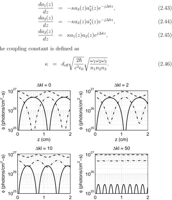
κ = deff r 2~ c3² 0 r ω1ω2ω3 n1n2n3 . (2.46) 0 1 2 1025 1026 1027 z (cm) φ (photons/cm 2 −s) ∆kl = 0 0 1 2 1025 1026 1027 z (cm) φ (photons/cm 2 −s) ∆kl = 2 0 1 2 1025 1026 1027 z (cm) φ (photons/cm 2 −s) ∆kl = 10 0 1 2 1025 1026 1027 z (cm) φ (photons/cm 2 −s) ∆kl = 50
Figure 2.1: Photon flux densities φ1 (dashed curves), φ2 (dashed-dotted curves),
and φ3 (solid curves) as functions of z for ∆kl = 0, 2, 10, and 50.
Figure 2.1 shows the evolution of photon flux densities inside a 2-cm-long (l = 2 cm) nonlinear crystal for ∆kl = 0, 2, 10, and 50, which are calculated using the Jacobi elliptic functions that are the solutions of Equations (2.43)– (2.45). A typical value of κ = 1 × 10⁻¹³ (in s1/2) is used for these calculations.
The initial values of the photon flux densities are φ3(0) = 0, φ2(0) = 5 × 1026,
and φ1(0) = 1 × 1027 photons/cm2-s.
The first subplot shown in Fig. 2.1 is for the phase-matched SFG (∆k = 0). Since φ3(0) = 0, the sum-frequency field at ω3 is generated with the correct
phase that provides the optimum relative phase for SFG, hence φ3 grows up to
a maximum value of 5 × 1026 photons/cm2-s which occurs at z = 0.6 cm. At
this point, φ2 is fully depleted, the field at ω2 (or signal) is generated with the
correct phase for DFG, and the photons in the sum-frequency field starts to be depleted by backconversion into the signal and idler fields. The backconversion ends at z = 1.2 cm where φ3(0) = 0 and SFG starts again. This cyclic behavior
continues along the length of the crystal. It should be noted that two quantities,
φ1(z)+φ3(z) and φ2(z)+φ3(z) are constant along the length of the crystal, which
are known as Manley-Rowe conserved quantities [105].
In the subplots of Fig. 2.1 where ∆k 6= 0, the initial relative phase θ of the fields evolve continuously along the length of the crystal, rather than making jumps between −90◦ and 90◦ at only discrete locations where the photon flux of a field goes to zero. As the strength of the phase-mismatch increases, the gener-ation process reverses from SFG to DFG (or DFG to SFG) at shorter distances and hence the generation efficiency decreases. For instance, in the subplot with ∆kl = 50, φ3 can only attain a maximum value of 2.9 × 1025 photons/cm2-s and
φ1 and φ2 remain almost undepleted. Consequently, phase-matching is of prime
importance for a nonlinear interaction to take place efficiently.
We also note that when the sum-frequency field is absent at the crystal input and the interaction is phase-matched (∆k = 0), the relative phase relation for optimum SFG is readily satisfied when ai are real numbers in the expressions for
Ai [Equations (2.40–2.42)]. In this case, a2i represent the photon flux densities φi and Equations (2.43)–(2.45) can be simplified in appearance by setting ∆k = 0 and replacing a∗
2.5
Second-Harmonic Generation
In SHG, the fundamental fields are both at ω1 = ω2 = ω and the second-harmonic
field is at ω3 = 2ω. If type-I phase-matching geometry is used, the fundamental
fields are indistinguishable from each other since they are polarized along the same direction in addition to having identical frequencies. In type-II phase-matching geometry, the polarizations of the input fields are orthogonal to each other.
The coupled mode equations for the case of type-II phase matching are the same with an ordinary SFG process, which have been already given in the previous section. For the case of type-I phase matching, the coupled-equations are given as da1(z) dz = −κa3(z)a1(z), (2.47) da3(z) dz = 1 2κa 2 1(z), (2.48) where κ = deff r 2~ c3² 0 s 2ω3 n2 1n3 , (2.49)
In writing these equations, we assumed that there is perfect phase-matching (∆k = 0) and the sum-frequency field is absent at the input, hence ai are the real and normalized field amplitudes with A1 = (2~ω/n1c²0)1/2a1 and
A3 = −j (4~ω/n3c²0)1/2a3 and a2i = φi represent the photon flux densities.
Figure 2.2 shows the evolution of the photon flux densities φ1 and φ3 as
func-tions of the propagation distance z inside a 2-cm-long nonlinear crystal for type-I phase-matched SHG. For these calculations, κ = 1 × 10⁻¹³ (in s1/2), φ
3(0) = 0,
and φ1(0) = 8 × 1026 photons/cm2-s. In SHG, two input photons are
anni-hilated for creating a single photon at the second-harmonic frequency and the second-harmonic photon flux density φ3asymptotically reaches a value of φ1(0)/2.
Hence, at large distances, almost 100% photon conversion efficiency is possible. Furthermore, there is no backconversion of the second-harmonic field into the fundamental, which is a feature of type-I SHG.
0.0 0.5 1.0 1.5 2.0 1025 1026 1027 z (cm) φ (photons/cm 2 −s) φ1 φ3
Figure 2.2: Evolution of the photon flux densities inside the nonlinear crystal as functions of the propagation distance for phase-matched SHG.
2.6
Optical Parametric Amplifier
In an OPA, a pump field at ω3 and a signal field at ω2 at the input interact
in a nonlinear crystal to produce an idler field at ω1, and in this DFG process
the signal field is also amplified with a gain which will be denoted by G. We first give the coupled-mode equations for the phase-matched OPA and assume that the idler field is absent at the crystal input which enables us to write the equations for real and normalized field amplitudes ai. With these assumptions, Equations (2.31)–(2.33) can be rewritten in a simpler form by performing the following substitutions for Ai
A1(z) = −j r 2~ω1 n1c²0 a1(z), (2.50) A2(z) = r 2~ω2 n2c²0 a2(z), (2.51) A3(z) = r 2~ω3 n3c²0 a3(z), (2.52)
where the required phase relation for optimum downconversion or DFG is included above, hence ai are the real and normalized field amplitudes such that |ai|2 = φi represent the photon flux densities at each frequency ωi. In this case, the coupled-mode equations become
da1(z) dz = κa3(z)a2(z), (2.53) da2(z) dz = κa3(z)a1(z), (2.54) da3(z) dz = −κa1(z)a2(z), (2.55)
where the coupling constant κ is defined as in Equation (2.46).
The solutions of Equations (2.53)–(2.55) are given in terms of Jacobi elliptic functions as [106, 107] a1(z) = p C1cn(Za| ma), (2.56) a2(z) = p C2dn(Za| ma), (2.57) a3(z) = p C1sn(Za| ma), (2.58)
where C1 and C2 are the Manley-Rowe [105] conserved quantities given as
C1 = a21(z) + a23(z) = a23(0), (2.59) C2 = a22(z) + a23(z) = a22(0) + a23(0), (2.60) and ma = C1/C2, (2.61) Za = K(ma) − κa p C2z, (2.62) with K(m) = Z π/2 0 (1 − m sin2θ)−1/2dθ, (2.63) which is the definition of the quarter-period of the Jacobi elliptic functions, given by the complete elliptic integral of the first kind [108].
The gain for the signal field is defined as
G = φ2(z = l) φ2(z = 0)
where l is the length of the nonlinear crystal.
Figure 2.3 shows the evolution of the photon flux densities φ1, φ2 and φ3 as
functions of the propagation distance z inside a 2-cm-long (l = 2 cm) nonlin-ear crystal for the phase-matched OPA. The results are calculated using Equa-tions (2.56)–(2.58) with κ = 1 × 10⁻¹³ (in s1/2), φ
1(0) = 0, φ2(0) = 8 × 1024, and
φ3(0) = 8 × 1025 photons/cm2-s. The photon flux density of the signal (φ2) is
amplified with a corresponding gain of G = 6.9, whereas an idler field is generated with a photon flux density of 4.7 × 1025 photons/cm2-s at z = 2 cm.
0.0 0.5 1.0 1.5 2.0 0 1 2 3 4 5 6 7 8x 10 25 z (cm) φ (photons/cm 2 −s) φ1 φ2 φ3
Figure 2.3: Evolution of the photon flux densities as functions of the propagation distance for the phase-matched OPA. φ1, φ2, and φ3 denote the photon flux
densities of the idler, signal, and pump, respectively.
2.7
Optical Parametric Oscillator
A singly-resonant OPO is formed by placing the OPA inside an optical cavity that is resonant at the signal frequency. The signal field builds up from parametric noise if the unsaturated gain G0 is higher than all cavity losses combined, which
includes reflection, absorption, and scattering losses (residual losses) and the output coupling loss (useful loss) experienced by the intracavity signal field. In the steady state, an intracavity signal intensity assumes such a value that the saturated gain compensates for the losses exactly and the non-resonant idler leaves the cavity through the output mirror of the cavity that is highly transmitting at the idler frequency.
Denoting the reflectivity of the output coupling mirror of the cavity at the signal wavelength by Roc, the useful loss is Loc = 1 − Roc. The intracavity signal
photon flux density multiplied with the useful loss gives the signal photon flux density outside the cavity. Denoting the useless loss that the intracavity signal experiences by Ls, then the cavity reflectance can be written as
Rcav = Roc(1 − Ls). (2.65)
Hence, provided that unsaturated signal gain G0 is high enough to start up the
oscillation, the signal gain saturates to value that will yield a round-trip gain of 1 which means that the steady-state intracavity signal flux density at the crystal input is a solution of
G[φ2(z = 0)] =
1
Rcav
. (2.66)
Figure 2.4 shows the signal gain (G) of an OPA as a function of the signal photon flux density at the input [φ2(0)] normalized to the input pump photon
flux density [φ3(0)]. For this calculation, Equations (2.56)–(2.58) are employed
and the values used for κ and φ3(0) are the same with those given in the example
of the previous section. This OPA is placed into a cavity with Ls = 4% and
Roc = 60% which is resonant at the signal wavelength, resulting in an OPO. For
very low photon flux densities of the signal provided by the noise, G0 = 9.5, which
is well above the 1/Rcav level, hence the signal field grows in the cavity until the
saturated gain is G = 1.7 which compensates for the cavity losses exactly. At this steady-state point, the intracavity signal flux density is φ2(0) = 0.9φ3(0).
An important parameter in the OPO design is the nonlinear drive which is given by
D = (κl)2φ
10−4 10−2 100 1 2 3 4 5 6 7 8 9 10 φ2(0)/φ 3(0) Signal gain: φ 2 (l)/ φ 2 (0) steady−state point
Figure 2.4: Signal gain (G) as a function of the normalized signal photon flux density at the input. 1/Rcav level is also indicated by a dashed line. The
intersec-tion point corresponds to the steady-state intracavity signal flux density at the crystal input and the saturated gain.
Equations (2.56)–(2.58) can be solved assuming that the pump remains unde-pleted in the interaction and it can be shown that the small-signal or unsaturated gain is given by
G0 = cosh2(
√
D). (2.68)
The threshold value of the input pump photon flux density can be found by solving G0Rcav = 1 for D. The threshold photon flux density decreases with
increasing κ, l and decreasing cavity losses. When Roc = 0, there is no output
coupling and when Roc = 100%, the oscillation will never start, therefore there is
an optimum output coupler reflectivity that yields the maximum signal output at a given pump power. However, the threshold will decrease and downconversion efficiency will increase simultaneously with a decrease in the useless cavity loss, increase in the crystal length and the deff value of the crystal, provided that the
pump limit beyond which there will be backconversion into the pump field is not reached, which is unlikely for OPOs operating in the steady-state regime.
2.8
Simultaneously Phase-Matched Interactions
An OPO by itself can provide only downconversion of a pump field into the lower-frequency signal and idler fields. Upconversion is possible through the use of OPOs which are simultaneously phase-matched for SHG or SFG along with the parametric generation. These devices provide efficient conversion by using the high-intensity intracavity fields which are otherwise unavailable if a second crystal is placed external to the OPO cavity for upconversion. Several experimental demonstrations of devices which employ two crystals placed internal to the cavity, one for parametric interaction and the other for SHG or SFG, were also reported [109, 110]. However, this second crystal increases the system complexity and the conversion efficiencies provided by these devices are still lower than those of the single-crystal devices where parametric interaction and SHG or SFG occur simultaneously rather than being separated from each other.Plane-wave theories for the self-doubling OPOs (SD-OPOs) and sum-frequency generating OPOs (SF-OPOs) using simultaneous phase matching were previously reported by Ayt¨ur et al. [58] and Dikmelik et al. [59]. In these devices, both parametric generation and SHG or both parametric generation and SFG can be phase matched for the same direction of propagation inside the nonlinear crystal. The cavities of these devices are singly-resonant at the signal wavelength and have only a few percent of residual losses for the signal. The output coupling is not linear as provided by an output mirror in the OPOs, but is through the generation of an upconverted field, hence the output coupling mechanism is non-linear. The cavity mirrors are also transparent to the generated second-harmonic or sum-frequency beams.
For SD-OPOs, six polarization geometries are possible depending on the types of OPO and SHG phase matching. Some of these geometries require an intracavity polarization rotation for the signal field while others do not. These polarization geometries can be further grouped under three different classes A, B, or C which are designated depending on the set of coupled-mode equations to be used for the plane-wave description of the SD-OPO. Table 2.1 lists these classes with the corresponding state of the rotation of the intracavity signal polarization and the
corresponding phase-matching polarization geometries of the OPO and SHG.1
Class Rotation OPO SHG
A no type-I
type-II type-I
B yes type-II type-I
C yes type-I
type-II type-II
Table 2.1: Phase matching geometries for the SD-OPO.
In particular, for a class-A SD-OPO, the polarization of the OPO signal is the same as that of the SHG fundamental. As a result, the signal field is common to the OPO and SHG processes, which become coupled to each other through the signal field. The set of coupled-mode equations describing this simultaneously phase-matched interaction is da1(z) dz = κaa3(z)a2(z), (2.69) da2(z) dz = κaa3(z)a1(z) − κba6(z)a2(z), (2.70) da3(z) dz = −κaa1(z)a2(z), (2.71) da6(z) dz = 1 2κba 2 2(z), (2.72)
where ai are the real and normalized field amplitudes such that a2i = φi represent the photon flux densities at each frequency ωi, i = 1, 2, 3, and 6 are for the idler, the signal, the pump, and the second-harmonic fields, respectively, and
κa and κb are the coupling constants for the parametric generation and SHG 1In this dissertation, we do not consider type-III as another type of phase matching. Instead, we label both type-II and type-III as type-II, which means that when only one of the lower frequency fields (the signal and idler for the OPO or the input fields for SHG or SFG), but not both, has a polarization that is orthogonal to that of the highest frequency field (the pump for the OPO and the second-harmonic and sum-frequency fields for the SHG and SFG, respectively) of the particular process, this is a type-II phase matching. If both of the lower frequency fields have polarizations orthogonal to that of the highest frequency field, this is a type-I phase matching. Also, as it will be explained in the next section, in BPM, the highest frequency fields in both processes (OPO and SHG or OPO and SFG) should be polarized along the fast axis of the crystal.