SELF-ASSEMBLED PEPTIDE BASED BIOMATERIALS FOR
DRUG DELIVERY AND REGENERATIVE MEDICINE
A DISSERTATION SUBMITTED TO
THE GRADUATE SCHOOL OF ENGINEERING AND SCIENCE OF BILKENT UNIVERSITY
IN PARTIAL FULFILLMENT OF THE REQUIREMENTS FOR THE DEGREE OF
DOCTOR OF PHILOSOPHY IN
MATERIALS SCIENCE AND NANOTECHNOLOGY
By Göksu Çinar
ii
SELF-ASSEMBLED PEPTIDE BASED BIOMATERIALS FOR DRUG DELIVERY AND REGENERATIVE MEDICINE
By Göksu Çinar June 2016
We certify that we have read this dissertation and that in our opinion it is fully adequate, in scope and in quality, as a dissertation for the degree of Doctor of Philosophy.
Mustafa Özgür Güler (Advisor)
Ayşe Begüm Tekinay
Semra İde
Aykutlu Dana
İrem Erel Göktepe
Approved for the Graduate School of Engineering and Science:
Levent Onural
iii
ABSTRACT
SELF-ASSEMBLED PEPTIDE BASED BIOMATERIALS FOR DRUG DELIVERY AND REGENERATIVE MEDICINE
Göksu Çinar
Ph.D. in Materials Science and Nanotechnology Advisor: Mustafa Özgür Güler
June, 2016
Self-assembly is a nature inspired novel engineering tool to build functional new generation of adaptable and complex biomaterials with variety of chemical and physical properties based on recent discoveries at the interface of chemistry, biology and materials science. Within self-assembling building blocks, peptides consisting natural amino acids and possibilities to integrate other molecules via synthetic approaches are intriguing biomacromolecules to obtain dynamic architectures at both nano and bulk scales for biomedical applications. In this thesis, the development of novel biomaterials through molecular self-assembly of the biomimetic peptides, bioactive peptide amphiphiles and their composite architectures with polymeric system for biomedical applications were presented. In the first chapter, the concept of self-assembly, design principles of the self-assembling peptide based building blocks and advanced characterization techniques for these materials were discussed to provide general perspective on the field. The applications of peptide based biomaterials with an emphasis on the drug delivery and regenerative medicine purposes were also highlighted in this part. In the second chapter, amyloid inspired self-assembling
iv
peptides and their supramolecular assemblies were presented in the context of developing nature-inspired biocompatible and mechanically stable supramolecular peptide based biomaterials. In the third chapter, supramolecular PA nanofiber gels which can form supramolecular nanofibrous networks at physiological conditions and encapsulate chemotherapeutics with high efficacy were examined as controlled local drug delivery system at both in vitro and in vivo conditions. In the fourth chapter, the facile fabrication strategy to create a novel self-assembled peptide amphiphile (PA) nanofibers and PEG composite hydrogel system as synthetic ECM analogues was discussed. It was showed that the synergistic combination of different classes of materials provide us new opportunities to develop biomaterials with independently tunable biochemical, mechanical and physical properties.
Keywords: Self-assembly, biomaterials, amyloid inspired peptides, peptide amphiphiles, nanofibers, supramolecular nanofiber gels, drug delivery, controlled drug release and regenerative medicine
v
ÖZET
MOLEKÜLER KONTROLLÜ BİR ARAYA GELME YÖNTEMİYLE OLUŞTURULAN PEPTİT BAZLI BİYOMALZEMELERİN İLAÇ TAŞINIMI
VE REJENERATİF TIP ALANLARINDA UYGULAMALARI
Göksu Çinar
Malzeme Bilimi ve Nanoteknoloji, Doktora Tez Danışmanı: Mustafa Özgür Güler
Haziran, 2016
Moleküler kontrollü kendiliğinden bir araya gelme, farklı fiziksel ve kimyasal özelliklere sahip yeni nesil malzemelerin üretilmesinde kullanılan doğadan esinlenerek geliştirilmiş bir yöntemdir. Günümüzde bu malzemeleri oluşturan moleküler düzeyde kontrol edilebilir yapı taşları; kimya, biyoloji ve malzeme bilimi gibi farklı bilimsel disiplinlerin ortak yaklaşımlarıyla geliştirilmektedir. Doğada bulunan yapı taşları içerisinde, peptit molekülleri kendilerini oluşturan amino asitler arasındaki kovalent olmayan etkileşimler yardımıyla programlanarak; dinamik ve çevresel etkilere duyarlı çeşitli biyomalzemelerin nano veya makro düzeydeki inşasında kullanılmaktadır. Bu tez çalışmasında, doğadaki akıllı tasarımlardan esinlenerek geliştirilmiş kendiliğinden bir araya gelerek elde edilen peptit tabanlı farklı biyomalzemelerin üretilmesi, malzeme özelliklerinin belirlenmesi ve farklı biyomedikal alanlardaki uygulamaları sunulmuştur. İlk kısımda, moleküler kontrollü bir araya gelme prensipleri, bu özelliğe sahip peptit tabanlı yapı tasarım stratejileri ve bu yapıların oluşturdukları malzemeler için kullanılan yeni nesil karakterizasyon
vi
yöntemleri literatürdeki örnekler ışığında tartışılmıştır. İkinci kısımda, nörodejeneratif hastalıklara sebep olan amiloid peptit yapılarından esinlenerek tasarlanan peptit moleküllerinin kendiliğinden bir araya gelme davranışları, fizyolojik koşullarda oluşturdukları nanofiber ve supramoleküler jellerin malzeme özellikleri ve biyouyumlulukları incelenmiştir. Üçüncü bölümde, kemoterapötik ilaçların lokal bölgelere taşınımı hedefleyen supramoleküler peptit amfifil nanofiber jellerin geliştirilmesi, kontrollü ilaç salım davranışları ve ilaç taşıma sistemi olarak uygulanabilirliği in vitro ve in vivo koşullarda incelenmiştir. Dördüncü kısımda, peptit amfifil ağsı nanofiberleri ve kimyasal çapraz bağlanmış PEG ikili yapı iskelesi içeren biyoaktif doğal ekstraselüler matriks benzeri biyomalzemelerin, kompozit malzeme stratejisi kullanılarak geliştirilmesi incelenmiştir. Hücre-biyomalzeme etkileşimleri ve rejeneratif tıp alanında uygulaması, 2 ve 3 boyutlu in vitro hücre kültür ortamında test edilmiştir.
Anahtar kelimeler: Kendiliğinden bir araya gelme, biyomalzemeler, amiloid benzeri peptitler, peptit amfifiller, nanofiberler, supramoleküler nanofiber jeller, ilaç taşınımı, kontrollü ilaç salımı ve rejeneratif tıp
vii
Acknowledgement
I would like to express my deepest appreciation to my PhD advisor Prof. Mustafa Özgür Güler for his scientific knowledge and support throughout my graduate studies. He always encouraged me to put my thoughts into the practice within the scientific research perspective. I am also sincerely grateful to Prof. Ayşe Begüm Tekinay, Prof. Dr. Semra İde and Prof. Aykutlu Dana and for their knowledge, guidance and support during my PhD studies. I would like to thank my jury members for their contribution to my thesis.
I would like to express my special thanks to Prof. E. Deniz Tekin, Dr. Ayşe Özdemir, Ilghar Orijalipoor, Dr. Ruslan Garifullin, Dr. Rashad Mammadov, Dr. Hakan Ceylan, Dr. Aslı Çelebioğlu, Mustafa Ürel, Turan Selman Erkal and Melis Göktaş for their scientific knowledge and fruitful collaboration.
Being a member of BML is a privilege for me and I would like to acknowledge my previous and present lab and office members. I have special thanks to Dr. Handan Acar, Dr. Adem Yıldırım, Dr. Gözde Uzunallı, Dr. Seher Üstün Yaylacı, Dr. Gülcihan Gülseren, Dr. Özlem Erol, M. Aref Khalily, Gökhan Günay, Egemen Deniz Eren, Gülistan Tansık, Melike Sever, Alper Devrim Özkan, Berna Şentürk, Zeynep Aytaç, Yelda Ertaş, Samet Kocabey, Elif Arslan, Yasin Tümtaş, Didem Mumcuoğlu, Özüm Şehnaz Günel, Ahmet Emin Topal, Hepi Susapto, Begüm Dikeçoğlu, Oya İlke Şentürk, Hatice Kübra Kara, Aygül Zengin and Meryem Hatip for their friendship during my PhD in UNAM. I also thank to Mrs. Zeynep Erdoğan and Mr. Mustafa Güler for their technical contribution to my thesis.
viii
I would like to acknowledge The Scientific and Technological Research Council of Turkey (TÜBİTAK BIDEB-2211C, 112T452 and 213M406) for funding my PhD research and financially supporting me in one international conference (2224-A).
I am so lucky and grateful to have my dearest friends Melis Şardan Ekiz, Oya Ustahüseyin, Okan Öner Ekiz, Bihter Dağlar, Seren Hamsici, Neşe Çakmak, Can Görür, Arda Yıldırım, Zeynep Erge Akbaş, Büşra Aşık, Cansu Ultav, Gözde Ultav and Nagihan Yalçınkaya. I appreciate their endless support and friendship throughout my life.
I would like to give my special thanks to Ali Çiftçi, Bilgin Çiftçi, Belgin Özdemir Fikri Özdemir and Bilge Özdemir for their love and support.
I would like to express my most sincere gratitude to my family, my mother Ayla Çinar, my father Güngör Çinar, my little sister Gökçe Çinar, my grandfather Mustafa Çinar and my super-grandmother Mevlüde Çinar for their endless love, encouragement and unquestionable belief in me. Without their support, I would not be able to finish this thesis.
Finally, I would like to express most heartfelt thankfulness to my partner, Barış Çiftçi, for his support, patience and encouragement throughout my life. My greatest accomplishment in life is to deserve his endless love. I dedicate this thesis to him.
ix
Contents
ABSTRACT ... iii
ÖZET... v
Acknowledgement... vii
List of Figures ... xiv
List of Tables... xxv Abbreviations ... xxvi Chapter 1 ... 1 1. Introduction ... 1 1.1 Self-Assembly ... 1 1.2 Peptide Self-Assembly ... 4
1.3 Design of Self-Assembling Peptide Based Building Blocks ... 6
1.3.1 Peptides Composed of Only Amino Acids ... 6
1.3.2 Peptide Amphiphiles ... 10
1.3.3 Peptide Containing Other Hybrid Systems ... 14
1.4 Characterizations of Self-Assembled Peptide Based Materials ... 17
1.4.1 Spectroscopic Techniques ... 18
1.4.3 Imaging Techniques ... 24
1.4.4 Mechanical Characterization Techniques ... 26
1.5 Applications of Self-Assembled Peptide Based Biomaterials ... 30
1.5.1 Drug Delivery... 30
1.5.2 Regenerative Medicine ... 34
x
2. . Amyloid Inspired Self-assembling Peptides (AIPs) and Their Supramolecular
Assemblies ... 37
2.1 Introduction ... 37
2.2 Experimental Section ... 41
2.2.1 Materials ... 41
2.2.2 Synthesis and Characterizations of AIPs ... 41
2.2.3 Zeta Potential Measurements of AIPs ... 42
2.2.4 Scanning Electron Microscopy ... 42
2.2.5 Transmission Electron Microscopy... 43
2.2.6 Molecular Dynamics Simulations ... 43
2.2.7 CD Analysis ... 44
2.2.8 FTIR Analysis ... 45
2.2.9 Congo-red Staining ... 45
2.2.10 ThT Binding Assay and Confocal Fluorescence Imaging ... 45
2.2.11 Turbidity Assay ... 47
2.2.12 SAXS Measurements and Data Fitting ... 47
2.2.13 Oscillatory Rheology ... 52
2.2.14 Atomic Force Microscopy ... 53
2.2.15 In Vitro Studies ... 54
2.3. Results and Discussion ... 55
2.3.1 Synthesis and Characterization of AIPs ... 55
2.3.2 Coassembly of AIPs into Nanofibers and Supramolecular Gels ... 57
2.3.2.1 Molecular Dynamics Simulation of AIP Coassembly ... 60
xi
2.3.2.3 Coassembly Kinetics of AIPs... 67
2.3.2.4 SAXS Analysis of AIP Nanofibers ... 75
2.3.3 Viscoelastic Properties of AIP Supramolecular Gels... 82
2.3.4 Nanomechanical Properties of AIP Nanofibers ... 87
2.3.5 Biocompatibility of AIP Nanofibers and Supramolecular Gels ... 94
2.4 Conclusion ... 99
Chapter 3 ... 102
3. Controlled Local Chemotherapeutic Drug Delivery through Supramolecular Peptide Amphiphile (PA) Nanofiber Gels ... 102
3.1 Introduction ... 102
3.2 Experimental Section ... 103
3.2.1 Materials ... 103
3.2.2 Synthesis and Characterization of PA Molecules ... 103
3.2.3 Preparation of the PA Nanofiber Gels ... 104
3.2.4 Imaging of the PA Nanofibers and Gels ... 104
3.2.5 Zeta Potential Measurements ... 105
3.2.6 Secondary Structure Analysis using CD and FTIR... 105
3.2.7 Oscillatory Rheology ... 106
3.2.8 Controlled Drug Release Experiments ... 106
3.2.9 FRAP measurements ... 107
3.2.10 In Vitro Studies ... 107
3.2.11 4T1 Tumor Model and In Vivo Studies ... 108
3.2.12 Statistical Analysis ... 109
xii
3.3.1 Design, Synthesis and Characterizations of the PA Assemblies and
Nanofiber Gels ... 110
3.3.2 Biodegradability of the PA Nanofiber Gels ... 115
3.3.3 Drug Encapsulation and Controlled Drug Release through the PA Nanofiber Gels ... 117
3.3.4 In Vitro Biocompatibility of the PA Nanofiber Gels ... 122
3.3.5 In Vivo Applicability of the PA Nanofiber Gels ... 125
3.4 Conclusion ... 128
Chapter 4 ... 130
4. Self-Assembled Peptide Amphiphile Nanofibers and PEG Composite Hydrogels As Tunable ECM Mimetic Biomaterials ... 130
4.1 Introduction ... 130
4.2 Experimental Section ... 133
4.2.1 Materials ... 133
4.2.2 Synthesis and Characterizations of the Bioactive PA Molecules ... 134
4.2.3 PA/PEG Composite Hydrogels Preparation ... 135
4.2.4 Transmission Electron Microscopy Imaging ... 136
4.2.5 Scanning Electron Microscopy Imaging ... 136
4.2.6 Attenuated Total Reflectance-Fourier Transform Infrared Spectroscopy (ATR-FTIR) ... 137
4.2.8 SAXS Analysis of the PA/PEG Composite Hydrogels ... 138
4.2.9 Oscillatory Rheology ... 138
4.2.10 In Vitro Studies ... 139
xiii
4.3 Results and discussion ... 144
4.3.1 Design, Synthesis and Characterizations of the Bioactive PA Molecules ... 144
4.3.2 Chemical and Physical Characterizations of the PA/PEG Composite Hydrogels ... 148
4.3.3 In Vitro Studies ... 161
4.3.4 Protein Encapsulation and Controlled Protein Release through the PA/PEG Composite Hydrogels ... 172
4.4 Conclusion ... 176
Chapter 5 ... 177
5. Conclusion and Future Prospects ... 177
xiv
List of Figures
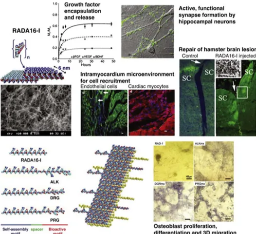
Figure 1.1 Strength and properties of chemical interactions... 1 Figure 1.2 Programmable self-assembly of simple or informed components. A variety of simple supramolecular architectures including peptide amphiphile nanofibers, nanoparticle polymers, vortex crystals and nanoparticle assemblies; and complex hierarchical architectures such as the ribosome or DNA bricks. (Adapted from Ref. 7 with permission from Nature Publishing Group) ... 3 Figure 1.3 Schematic representation of the different class of amino acids and non-covalent interactions involved in the peptide self-assembly. (Reproduced from Ref. 11 with permission from Royal Society of Chemistry) ... 5 Figure 1.4 Self-assembling peptide building blocks consisting only natural amino acids and their supramolecular assemblies. (Adapted from Ref. 1 with permission from Wiley Periodicals, Inc.) ... 7 Figure 1.5 Schematic representation, CD spectra and AFM images of the design of the self-assembled K-PA nanofibers and P-PA nanospheres developed as the oligonucleotide (ODN) carriers to modulate immune response. (Adapted from Ref. 54 with permission from Nature Publishing Group) ... 13 Figure 1.6 Common characterization techniques for variety of self-assembled peptide nanostructures ... 17 Figure 1.7 The detailed structural model of a self-assembled peptide-based nanocarrier developed in the light of the solid-state NMR (ssNMR) experiments. (Reproduced from Ref. 105 with permission from American Chemical Society) ... 19 Figure 1.8 The scattering (a) and electron density (b) profiles of the self-assembled arginine-capped peptide bolaamphiphile assemblies prepared at different
xv
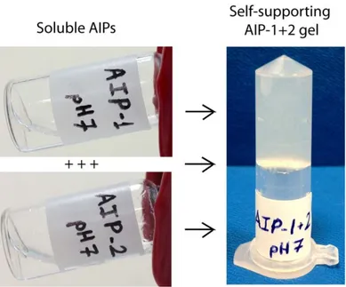
concentrations and the fitting lines of the model according to a bilayer form factor. (Reproduced from Ref. 18 with permission from American Chemical Society) ... 23 Figure 1.9 Label-free super-resolution imaging of the self-assembled amyloid inspired peptide structures by applying stochastic reconstruction to temporal fluctuations of the Surface Enhanced Raman Scattering (SERS) signal. (Reproduced from Ref. 123 with permission from Nature Publishing Group) ... 26 Figure 1.10 The nanomechanical characterizations of the D, L cyclic peptide assemblies. (Reproduced from Ref. 144 with permission from Nature Publishing Group) ... 29 Figure 1.11 Controlled drug delivery through self-assembled peptide assemblies via non-covalent encapsulation or covalent conjugation of the drug molecules (Adapted from Ref. 211 with permission from Royal Society of Chemistry) ... 32 Figure 1.12 Self-assembled RADA16-I peptide scaffolds examined for different regenerative medicine applications (Adapted from Ref. 236 with permission from Elsevier) ... 35 Figure 1.13 Self-assembled glycopeptide nanofibers and their supramolecular nanofiber gels promoted chondrogenesis and cartilage regeneration (Reproduced from Ref. 101 with permission from American Chemical Society) ... 36 Figure 2.1 The decoupling models which successfully describe the self-assembled AIPs nanostructures ... 51 Figure 2.2 Chemical representation of AIP-1 (a) and AIP-2 (b) peptides ... 56 Figure 2.3 a) AIP-1; [M-H]- (calculated): 752.33, [M-H]- (observed): 752.33. b)
RP-HPLC chromatogram of the AIP-1, the change of response units with respect to time at 220 nm. c) AIP-2; [M+H]+ (calculated): 752.44, [M+H]+ (observed): 752.45,
xvi
[2M+H]+ (calculated): 1503.88, [2M+H]+ (observed): 1503.89, [M/2+H]+
(calculated): 376.22, [M/2+H]+ (observed): 376.74. d) RP-HPLC chromatogram of the
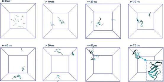
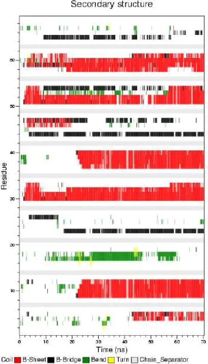
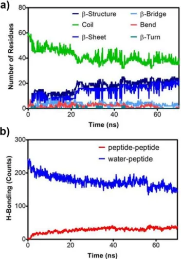
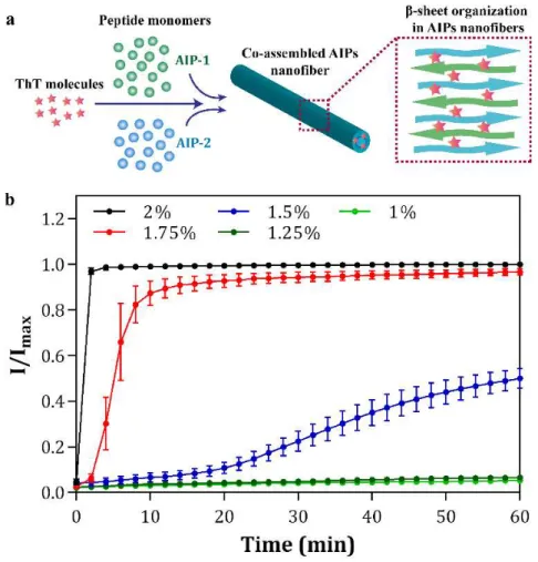
AIP-2, the change of response units with respect to time at 220 nm. ... 57 Figure 2.4 Zeta potentials of the AIP-1, AIP-2 solutions; and AIPs assemblies at pH 7.4 in water ... 58 Figure 2.5 TEM images of the coassembled AIP nanofibers (scale bar 10 nm, 50 nm and 0.1 µm) ... 59 Figure 2.6 Self-supporting 2% (w/v) coassembled AIP gel (AIP-1+2) formed after mixing AIP-1 and AIP-2 solutions at pH 7.4 in water ... 59 Figure 2.7 Selected snapshots of simulation of AIP-1 and AIP-2 peptides (five molecules per each peptide) obtained by 70 ns Molecular Dynamics Simulations ... 60 Figure 2.8 a) Hydrophobic core interactions (number of contacts) of AIP-1 and AIP-2 based on the residues of FFAA-FFAA, b) aromatic group contacts (number of contacts) of AIP-1 and AIP-2 based on the residues of FF-FF, c) Solvent Accessible Surface Area (SASA), d) coulomb interactions between -Lys and -Glu residues of AIP-1 and AIP-2, and e) potential energy change of the system during simulation. ... 6AIP-1 Figure 2.9 Residue based secondary structure change of peptides during simulation trajectory. ... 63 Figure 2.10 The secondary structure (a) and hydrogen bonding change (b) within the system during the simulation ... 64 Figure 2.11 a) Secondary structure analysis of AIP-1+2 nanofibers at various concentrations of dried AIP-1+2 gels with FTIR. b) Detailed analysis of Amide I region (1600-1700 cm-1) ... 65
xvii
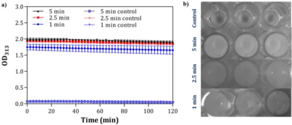
Figure 2.12 FTIR spectra of the coassembled AIP network (a, b) (- - - Gaussian fittings), molar ellipticity of the coassembled AIP (AIP-1+2), AIP-1 and AIP-2 assemblies (c); and the absorbance spectra of congo red dye with and without AIP coassemblies. ... 66 Figure 2.13 (a) A small fluorescent dye molecule; thioflavin T (ThT), is used as a probe for monitoring the coassembly of AIP-1 and AIP-2 molecules into nanostructures. (b) The normalized fluorescence intensity changes during the co-assembly process of the AIPs prepared at different peptide concentrations. ... 68 Figure 2.14 Time- and concentration-dependent co-assembly of oppositely charged AIPs at physiological conditions into supramolecular nanostructures. The aggregation kinetics of the AIPs were visualized using in situ confocal microscopy imaging during the coassembly process at different concentrations (all image scale bars are 200 µm) ... 69 Figure 2.15 SEM images of the three dimensional nanofibrous 2%, 1.75% and 1.5% (w/v) AIPs networks coassembled for 1 h ... 70 Figure 2.16 Turbidity of AIP solutions at different concentrations was monitored as optical density at 313 nm under physiological conditions. Increase in the turbidity of the solutions correlate with nanostructure formation and sol-gel transition. AIP-1 and AIP-2 molecules rapidly self-assemble into the nanostructures a concentration over 1.25% (w/v) concentration within 1 h. ... 72 Figure 2.17 Time dependent turbidity change of (a) AIP-1 and (b) AIP-2 at 313 nm, the peptide solutions were prepared at the different peptide concentrations. ... 73 Figure 2.18 Sonication enhances turbidity of 1% AIPs compared to the control groups; a) time dependent turbidity change and b) 1% AIPs solution images after the sonication
xviii
was applied for different time periods (1, 2.5 and 5 min) (Control groups were also 1% AIPs which were incubated for 5, 2.5 and 1 min without sonication prior to the analysis.)... 75 Figure 2.19 (a) Small angle X-ray scattering (SAXS) profiles and 2D patterns (b) of coassembled 2%, 1.75% and 1% (w/v) AIP nanostructures after 1 h. ... 76 Figure 2.20 The proposed structural model for co-assembled AIP nanostructures (a) and (b) the electron density distribution on the nanofiber, (c) AFM image of the coassembled AIP nanofibers and their bundles dried on a Si wafer ... 77 Figure 2.21 a) In situ SAXS measurements of 2% AIPs in water at neutral pH during coassembly, and (b) TEM images of the nanofibers prepared from the dilutions of coassembled 2% AIPs for 15 min (c) and (d) 60 min ... 80 Figure 2.22 a) SAXS profiles of 2% coassembled AIP nanostructures at different temperatures. (b) Increase in temperature did not disturb the organization of the AIP nanofibers and the density of the nanofibers slightly changed for elevated temperatures ... 81 Figure 2.23 Time sweep analysis (a) and (b) equilibrium storage (G′) and loss moduli (G′′) of the AIP coassemblies c) Linear dependence of storage moduli of the AIP gels to concentration change at pH 7 d) Damping factor (G′′/G′) change of the gels prepared at different concentrations of at pH 7 for 60 min. ... 83 Figure 2.24 Frequency sweep (a, b) and thixotropic analysis (c, d) of the AIP coassemblies prepared at different peptide concentrations at pH 7 (Loss Modulus, w: angular frequency) ... 84
xix
Figure 2.25 a) Time sweep analysis, and (b) equilibrium storage and loss moduli (G′, G′′) of the 2% (w/v) coassembled AIP, AIP-1 and AIP-2 gels prepared at pH 7, 5 and 10, respectively ... 86 Figure 2.26 Effect of temperature on the mechanical stability of coassembled 2% (w/v) supramolecular AIP nanostructure network for 1 h (The co-assembled network preserved viscoelastic behavior at elevated temperatures) ... 87 Figure 2.27 AFM topography images of coassembled AIP nanofibers (a); and adhesion force (b) and (c) elastic modulus maps of the nanofibers determined from the slope of force-distance curves (Modulus, Pa) during retraction ... 88 Figure 2.28 Adhesion force (a, c, e) and elastic modulus maps (b, d, f) of individual AIP-1 and AIP-2 nanofibers and the coassembled AIP nanofibers during approach 89 Figure 2.29 The topography (a,b), adhesion force (c,d) and elastic modulus maps (e, f) of individual AIP-1 and AIP-2 nanofibers during retraction ... 89 Figure 2.30 Slope (a, b) and adhesion force histograms (c, d) of the coassembled AIPs at pH 7 and individually formed AIP-1 at pH 5 and AIP-2 nanofibers at pH 10 during approach and retraction of the AFM tip (― Gaussian fittings). Schematic representation of nanofiber and AFM tip interactions during nanomechanical characterizations (e) ... 91 Figure 2.31 Modulus (Pa) histograms of AIP-1+2 at pH 7, AIP-1 at pH 5, and AIP-2 at pH 10 nanofibers; a) approach and b) retraction of AFM tip (―: Gaussian fittings) ... 93 Figure 2.32 Maximum force histogram of the coassembled AIP nanofibers at pH 7, AIP-1 at pH 5, and AIP-2 at pH 10 nanofibers applied by AFM tip during the nanomechanical characterizations ... 94
xx
Figure 2.33 a) Relative cell adhesion for 2 h, b) viability for 24 h; c) proliferation for 48 h; and d-f) the confocal images of the cells after 24 h cultured on the AIPs nanofibers, collagen I and bare glass. ... 95 Figure 2.34 Spreading of the cells on the AIPs nanofibes, collagen I and glass after 2 h based on a) cell diameter b) cell area (n.s.: Not significant). ... 96 Figure 2.35 The confocal images of the cells after 2 and 48 h cultured on the AIPs nanofibers, collagen I and bare glass. ... 97 Figure 2.36 SEM images of the coassembled AIPs coated surfaces incubated with the cells under standard cell culture conditions for 24 h... 98 Figure 2.37 SEM images of HUVECs cultured on the 3D coassembled AIPs gel surfaces after 24 h later ... 99 Figure 3.1 Liquid chromatograms and mass spectra of the synthesized PAs a) E3PA;
[M-H]- (calculated)= 912.50, [M-H]- (observed)= 912.48, (observed [M-2H]-2 m/z =
455.73) b) K3PA; [M+H]+ (calculated)= 910.67, [M+H]+ (observed)= 910.68,
(observed [M+2H]+2 m/z = 455.84) ... 110
Figure 3.2 a) Chemical representation of E3PA and K3PA molecules a) Zeta potential
change of the E3PA upon addition of the K3PA at pH 7.4 in water c) Supramolecular
PA network showed self-supporting gel property d) SEM and TEM image of the coassembled PA nanonetwork and nanofibers, respectively ... 111 Figure 3.3 SEM images of the self-assembled PA nanonetworks prepared using critical point dryer at different peptide concentrations ... 112 Figure 3.4 a) CD spectra of E3PA, K3PA and E3/K3PA and (b, c) the FTIR analysis of
xxi
Figure 3.5 a) Time sweep analysis of the supramolecular PA nanofiber gels prepared at the different concentrations and b) Equilibrium storage (G') and loss moduli (G'') of the PA gels. ... 114 Figure 3.6 a) Time sweep analysis of the 1% (w/v) coassembled PA gels injected through a syringe or directly mixed on the rheometer stage b) Equilibrium storage (G') and loss moduli (G'') of the PA nanofiber gels. ... 115 Figure 3.7 Biodegradability of 1% (w/v) coassembled PA nanofiber gel via different proteases at pH 7.4 in Tris buffer ... 116 Figure 3.8 Schematic representation of the drug encapsulation and coassembly of the molecules into supramolecular PA nanofiber gel ... 117 Figure 3.9 a) Controlled release profile of Dox through the PA gels prepared at different concentrations at physiological conditions and b) The release ratios of the chemotherapeutic drug were modulated depending on the PA concentration within the gels. ... 119 Figure 3.10 Mathematical fitting results of FRAP experiments a) the estimated diffusion constants and b) immobile fractions of the drug molecules encapsulated within the PA gels prepared at the different concentrations ... 120 Figure 3.11 Hankel transform of the photobleaching profiles of Dox encapsulated self-assembled PA hydrogels prepared at different concentrations. ... 122 Figure 3.12 Cellular viability on (a) the control, (b) 1% (w/v) PA gel, (c) 1% (w/v) Dox/PA gel and (d) only Dox for 24 h and 48 h. ... 123 Figure 3.13 Flow cytometry histograms of only Dox, Dox/PA, only PA and control groups at (a) 24 and (b) 48 h ... 124
xxii
Figure 3.14 a) Tumor growth of the only Dox, only PA, Dox/PA and control groups for 18 days and b) the final tumor volume (mm3) at day 18 ... 126
Figure 3.15 Caspase 3 immunohistochemistry staining of the tumor tissues of a) only Dox, b) only PA, c) Dox/PA and d) control groups at day 18 ... 127 Figure 3.16 Histology staining of the different tissues obtained from the only Dox, only PA, Dox/PA and control groups at day 18 ... 128 Figure 4.1 Chemical representations of the synthesized PA molecules... 145 Figure 4.2 Liquid chromatography-mass spectrometry (LC-MS) results of the synthesized PAs ... 146 Figure 4.3 Transmission Electron Microscopy (TEM) images showing the nanofiber assembly of PA combinations. A), B) E3-PA/K3-PA; C), D) RGD-PA/ K3-PA; E), F)
DGEA-PA/ K3-PA ... 147
Figure 4.4 Schematic representation of the fabrication approach for the PA/PEG composite hydrogels... 149 Figure 4.5 a) The schematic of the crosslinking reaction; and b) FTIR spectra of PEG (w/o PNFs) and E3/PEG samples after 15 min of UV crosslinking ... 150
Figure 4.6 SEM images of PEG (w/o PA nanofibers, PNFs) and PA/PEG composite hydrogels (scale bars are 4 µm) ... 151 Figure 4.7 Total pore volume and specific surface area of the hydrogels. ... 152 Figure 4.8 The pore size distributions and cumulative pore volumes of only PEG and PA/PEG composite hydrogels ... 153 Figure 4.9 a) The scattering data and fitting model of the PEG and PA/PEG composite hydrogels with (b, c) the PDD histograms of the samples ... 154
xxiii
Figure 4.10 Illustration of the structural organization of E3/PEG composite hydrogel
using flexible cylinder-polydisperse length model ... 156 Figure 4.11 Equilibrium storage and loss moduli of the hydrogels ... 158 Figure 4.12 Equilibrium storage moduli (a) and limiting strain amplitude values (b) of the hydrogels prepared at different concentrations. Photographs of PA/PEG composite (c) and only PA hydrogel (d) with the same storage moduli. ... 159 Figure 4.13 Rheological characterizations of the hydrogels based on amplitude sweep analysis ... 160 Figure 4.14 Fluorescence images of Saos-2 cells cultured on PEG and PA/PEG composite hydrogels and stained with calcein-AM (green) and ethidium homodimer (red) (scale bars are 100 µm) ... 162 Figure 4.15 a) Fluorescence images of Saos-2 cells cultured on stiff PEG and PA/PEG (prepared with E3-PA) composite hydrogels and stained with calcein-AM, b) he
number of adhered cells on the all systems at 24 h in serum free culture conditions, c) the fluorescence images of the cells stained with phalloidin (green); and d) the spreading areas of the cells cultured on the substances at 72 h ... 163 Figure 4.16 Fluorescence images of Saos-2 cells cultured on stiff PEG and PA/PEG (prepared with E3-PA) composite hydrogels and stained with calcein-AM (scale bars
are 200 µm) ... 164 Figure 4.17 Representative fluorescence images of the cells with ICC staining at day 7 (scale bars are 50 µm). Green indicated RUNX2 and COL1 expressions at the top and bottom row images, respectively. In both rows, phalloidin staining was shown as red color ... 166
xxiv
Figure 4.18 The gene expression levels of the cells cultured on PEG and PA/PEG composite hydrogels at day 3 ... 167 Figure 4.19 The gene expression levels of the cells cultured on PEG and PA/PEG composite hydrogels at day 3 and 7 ... 168 Figure 4.20 Fluorescence images of Saos-2 cells cultured within the 3D PEG and PA/PEG composite hydrogels and stained with calcein-AM (green) and ethidium homodimer (red) (scale bars are 100 µm) ... 171 Figure 4.21 The standard calibration curve for the determination of BSA concentration based on absorbance measurements ... 173 Figure 4.22 The controlled release profiles of the BSA molecules through the only PEG and PA/PEG composite hydrogels ... 174 Figure 4.23 The estimated apparent diffusion coefficients ... 175
xxv
List of Tables
Table 1.1 Recently reported self-assembling peptide hybrid systems ... 14 Table 2.1 Gaussian fitting parameters of FTIR data of AIP-1+2 self-assembled peptide nanofibers (see Figure 3c) obtained from MATLAB fitting program ... 65 Table 2.2 Fitting results of SAXS data of coassembled AIP nanostructures at different concentrations in water at neutral pH... 78 Table 2.3 Recovery of 4, 3, 2, 1 and 0.5% (w/v) coassembled AIP gels after disruption of the networks with the increased strain ... 84 Table 4.1 Bioinspired self-assembling PA building blocks ... 144 Table 4.2 Nomenclature and composition of PEG (w/o PA nanofibers (PNFs)) and PA/PEG composite hydrogels ... 145 Table 4.3 Structural results obtained from the fitting process of E3/PEG scattering data
xxvi
Abbreviations
AIP Amyloid-inspired peptide
AFM Atomic force microscopy
ANOVA Analysis of variance
ATR Attenuated total reflectance
BET Brunauer-Emmett-Teller
Boc Tert-butoxycarbonyl
CD Circular dichroism
Col-1 Collagen-1
CPP Critical packing parameter
DCM Dichloromethane
DIEA N,N-diisopropylethylamine
DMEM Dulbecco's modified Eagle's medium
DMF N,N-Dimethylformamide
ECM Extracellular matrix
EPR Electron paramagnetic resonance
ESI Electrospray ionization
FBS Fetal bovine serum
Fmoc 9-Fluorenylmethoxycarbonyl
FTIR Fourier transform infrared spectroscopy
GAG Glycosaminoglycan
GAPDH Glyceraldehyde 3-phosphate dehydrogenase HBTU N,N,N′,N′-Tetramethyl-O-(1H-benzotriazole-1-yl)
uronium hexafluorophosphate
hMSC Human mesenchymal stem cells
HPLC High pressure liquid chromatography HUVEC Human umbilical vein endothelial cell
ICC Immunocytochemistry
LC-MS Liquid chromatography-mass spectroscopy
LSA Limiting strain amplitude
xxvii
MD Molecular dynamics
MDP Multidomain peptide
NMR Nuclear magnetic resonance
OD Optical density
PA Peptide amphiphile
PBS Phosphate buffered saline
PDD Pair distance distributions
PEG Polyethylene glycol
PEGDMA Polyethylene glycol dimethacrylate PNAA Peptide nucleic acid amphiphile
PNFs Peptide nanofibers
qRT-PCR Quantitative real-time polymerase chain reaction
QTOF Quadrapole time of flight
ROI Region of interest
SAXS Small angle X-ray scattering
SD Standard deviation
SERS Surface enhanced Raman scattering
SEM Standard error of mean
SEM Scanning electron microscopy
SLP Surfactant like peptide
TCP Tissue culture plate
TEM Transmission electron microscopy
TFA Trifluoroacetic acid
ThT Thioflavin T
TIS Triisopropyl silane
UV Ultraviolet
VMD Visual molecular dynamics
1
Chapter 1
1. Introduction
1.1 Self-Assembly
Self-assembly is a ubiquitous process of nature, and it has numerous important roles for the construction of a wide variety of complex biological architectures.[1] It is defined as the spontaneous organization of the molecules into dynamic structures architectures joined through the noncovalent interactions.[2] The lipid bilayer cell membrane, actin filaments, capsid proteins of the viruses, collagen fibers are well-known hierarchical self-assembled architectures found in natural organisms.[3, 4] Molecular self-assembly is an emerging powerful tool within bottom up approaches takes the advantages of noncovalent interactions including hydrogen bonding, van der Waals, electrostatic, π-π, hydrophilic and hydrophobic interactions etc.[5] Although individually, these types of non-covalent bonds are usually weak compare to the covalent systems (Figure 1.1), they drive the self-assembly process and guide the structural organization of the building blocks into thermodynamically stable, complex and adaptable architectures when used in combination at the desired conditions.[6]
2
Over the past two decades, scientists and engineers have been inspired by nature's assembly principles to design simple or informed building blocks which can self-assembly into variety of functional nanoscale and bulk architectures (Figure 1.2).[7] The main advantage of this method is to anticipate size limitations of the top down approaches nanostructured materials via supramolecular chemistry without need of the equipments.[8] These self-assembled functional materials have been used in different applications including energy conversion and storage, electronics, photonics and biomedical purposes such as drug delivery, biosensing and tissue engineering.[9, 10]
3
Figure 1.2 Programmable self-assembly of simple or informed components. A variety of simple supramolecular architectures including peptide amphiphile nanofibers, nanoparticle polymers, vortex crystals and nanoparticle assemblies; and complex hierarchical architectures such as the ribosome or DNA bricks. (Adapted from Ref. 7 with permission from Nature Publishing Group)
4
1.2 Peptide Self-Assembly
Peptides consisting only natural or synthetic amino acids are able to form self-assembled nanostructures and supramolecular architectures depending on the intrinsic properties of the building blocks. Amino acids which are the building blocks of the peptide molecules exhibits variety of physiochemical properties due to different charge, hydrophobicity, size and polarity of their side chains. Non-polar amino acids, including aliphatic (alanine, leucine, valine) and aromatic (tyrosine, phenylalanine) amino acids, are mostly responsible for hydrophobic aggregation due to hydrophobic forces and π-π stacking, respectively. On the other hand, polar amino acids facilitate either hydrogen bonding or electrostatic interactions depending on their uncharged (serine, asparagine) or charged (lysine, histidine, glutamic acid) residues (Figure 1.3).[11] In addition to the side chain properties, the peptide backbone itself provides considerable stability through hydrogen bonds.
The stabilization of the multiple peptide backbone arrangements by hydrogen bonding interactions between the backbone amide and carbonyls results in the formation of β-sheets. The sheet is either parallel or anti-parallel depending on the direction of the strands. The α-helices are formed by individual peptide chains where backbone amide components are intramolecularly hydrogen bonded unlike the β-sheets. It leads to the presentation of the amino acid side chains on the surface of each helix and furtherly enhances the accessibility of amino acid side chains to solvent. In some cases, these single α- helices can assemble by coiling together and form so called coiled coils.
5
Figure 1.3 Schematic representation of the different class of amino acids and non-covalent interactions involved in the peptide self-assembly. (Reproduced from Ref. 11 with permission from Royal Society of Chemistry)
Peptide self-assembly is triggered via different external factors including pH, light, temperature, ultrasonication, ionic strength and solvent polarity due to the stimuli responsive dynamic nature of the noncovalent interactions between the peptide molecules.[12] In addition to the triggering the self-assembly process, these external
6
factors can be used to control and manipulate the structural properties such as size, shape or morphology of the self-assembled peptide architectures under different environmental conditions. This stimuli responsive nature of peptide self-assembly provide new opportunities to design materials which could satisfy the need of next generation devices and industries.
1.3 Design of Self-Assembling Peptide Based Building Blocks 1.3.1 Peptides Composed of Only Amino Acids
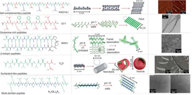
The distribution and the number of the hydrophobic and hydrophilic amino acids in the peptide sequence govern the final structural organization of the self-assembled peptides into nanofiber, nanotape, nanorod, nanovesicle, nanotube or micelle. Aggregation propensity and critical aggregation concentration (CAC) of the peptides can be modulated depending on the nature of the hydrophobic domain, which is very important for the stability of the assembly in aqueous environment.[13] The design of different self-assembling peptides consisting only natural amino acids and their supramolecular architectures formed via different triggering factors were given in Figure 1.4.[1]
Surfactant like peptides (SLPs) were designed as multiple 7-8 residue peptides consisting both consecutive hydrophobic residues (A6, V6, or L6) and hydrophilic
headgroup consisting one or two charged amino acid residues.[14] The type of nanostructure formed was mainly affected by the hydrophobicity of the tail but not by the number of integrated charged residues. The influence of the hydrophobic tail length on the formed SLP nanostructure was examined designing A3K, A6K, and A9K
peptides.[15] These peptides exhibited structural transition as their hydrophobic tail extended due to the change of packing within the nanostructure. While A3K
self-7
assembled into unstable peptide sheet stacks, A6K and A9K formed long
fibrillar-wormlike micelles and short nanorods, respectively.
Unlike the above-mentioned surfactant like peptides, the histidine attached hexaalanine sequence which had the ability to chelate to transition metal ions, particularly zinc cations, through its imidazole side chain were designed and synthesized.[16] In the study, the structural differences of the A6H assemblies prepared
in water and in ZnCl2 containing solution at neutral and acidic pH were compared,
respectively; and it was observed that while aqueous assemblies self-assembled into short sheets at pH 7, A6H dissolved in ZnCl2 solution formed pseudocrystalline
particles containing plate/tape like sheets.
Figure 1.4 Self-assembling peptide building blocks consisting only natural amino acids and their supramolecular assemblies. (Adapted from Ref. 1 with permission from Wiley Periodicals, Inc.)
8
Alternative to the classical design of traditional amphiphilic or SLPs, double-headed architecture of bolaamphiphiles (composed of hydrophobic core and two hydrophilic moieties flanking the both ends of the core) received a growing interest for their ability to form different self-assembled nanostructures.[17-19] It was reported that the designed linear octapeptide (EFL4FE) self-assembled into nanotubes at high
concentrations whereas they tended to form sheet like structures at lower concentrations.[20] Very recently, the researchers devised several phenylalanine containing bolaamphiphiles, (EFFFFE, KFFFFK, and EFFFFK), whose terminal charges were modulated to investigate the effect of electrostatic interactions on the resulting polymorphic nanostructure.[21] That led to the twisting of the β-sheet tapes and accordingly the formation of fibrils, twisted ribbons and belts.
Self-assembly can also be induced by utilizing specific chemical functionalities found in the peptide backbone. For instance, amphiphilic gemini peptides, formed as a result of linking two cysteine containing single chain peptides with disulfide bond through oxidation, were designed. Its self-assembly behavior was compared with that of the corresponding single chain counterparts.[22] Furthermore, three different hydrophobic amino acids (alanine, valine, and isoleucine) were chosen to tune the molecular hydrophobicity of the peptides and to study its effect on the self-assembly together with the dimerization.
Amphiphatic peptides arranged in an alternating fashion were firstly developed by Zhang group.[23-25] This ionic self-complementary peptides formed stable β-strand and β-sheet structures which further self-assembled into well-ordered nanofibers due to the electrostatic interactions. Beta sheets are putatively arranged into bilayer structures leading to the concealment of hydrophobic side chain groups within the
9
bilayer interior that exposes hydrophilic side chains into the aqueous media. The effect of sequence pattern variation on the self-assembly of amphiphatic peptides was dissected by using frequently studied Ac-(FKFE)2-Am peptide as a model.[26] It was
figured out that the alteration in the amino acid groupings and the disruption of the alternating pattern not only reduced the self-assembly ability but also changed the morphology of the resulting materials.
Multidomain peptides (MDPs) are another design example of the self-assembling peptides in which the displayed domains were arranged in an ABA block motif where B block composed of alternating hydrophilic and hydrophobic amino acid residues and peripheral A blocks employed charged amino acids to control the self-assembly through electrostatic interactions.[27, 28] The extended β-sheet conformation of the peptides led to creating a facial amphiphile. Packing of two of the hydrophobic faces against each other formed a “hydrophobic sandwich” which further elongated through antiparallel beta sheet hydrogen bonding. The self-assembly of MDPs was further explored by introducing aromatic amino acid residues into the core and it was concluded that hydrogen bonding pattern changed depending on the type of substituted aromatic amino acid without affecting the basic nanofiber morphology.[29]
10
1.3.2 Peptide Amphiphiles
Peptide amphiphiles (PAs) which are naturally found in living organism as functional molecules for bioprocesses are composed of both hydrophobic alkyl tail and hydrophilic peptide sequences.[30, 31] PA molecules can form diverse nanostructures and supramolecular architectures via different factors such as pH change[32], oppositely charged molecules[33, 34], metal ions[35] or enzyme activation[36]. The design of the PAs is based on the balance between hydrophobic alkyl tail length and hydrophilic amino acid sequences since amphiphilicity is the main driving force for the self-assembly of PA building blocks into well-defined supramolecular nanostructures.[37] The stability and flexibility of the resulting assemblies can be further improved by enhancing the amphiphaticity of PAs. The balance between hydrophobic and electrostatic interactions is needed to be taken into account while determining the geometry of amphiphiles with minimum free energy.[37] Since an alteration in the hydrophilic segment can lead to a change in the critical packing parameter (CPP)[38], it can affect the morphology of the overall assembly.[39, 40] The increase hydrophilicity towards the C-terminus of the designed PA molecule resulted the formation of the elongated self-assembled fibers due to pH triggering or salt induced charge neutralization of the acidic amino acid residues. Although both formulations exhibited similar morphologies, salt induced PA nanofibers formed stronger intra- and interfiber crosslinks through calcium mediated ionic bridges.[41] The same phenomena was also examined in another study using AFM nanoindentation technique, and the similar increase nanofiber stiffness due to Ca2+ crosslinking was
11
In addition, internal dynamics and fluctuations of supramolecular PA nanostructures have been studied in the help of quantitative electron paramagnetic resonance (EPR) spectroscopy in which local molecular motion within the assemblies can be tracked via site specific spin-label probes located at the PA molecules.[43] This technique also enable to reveal the relation between hydrogen bonding densities within β-sheet internal organization and the supramolecular cohesion of self-assembled PA nanostructures was effected by the design of the building blocks.[44]
In addition to the PA design examples given above, various self-assembling PA molecules which can self-assembly worm-like micelles due to their ɑ-helix propensities were also shown.[45, 46] Individual helices in the micellar state was obtained due to the symmetrically distributed of the lysine residues on the PA backnone[45]; and the resulting supramolecular nanostructures revealed time dependent morphological transition from spherical to long nanofibrillar structures. In another study, the effects of hydrophobic amino acid residues on the self-assembly of PA by addition of four alanine residues between the palmitic acid and oligopeptide sequence.[46] Interposing of hydrophobic alanine residues led to the structural transition on the morphology of corresponding PA from nanoribbons to worm-like micelles, further being confirmed by a secondary structural change from α-helices to β-sheets.
The oppositely charged PA molecules was also designed to trigger their coassembly due to the electrostatic interactions and charge screening of the PA molecules by simply mixing them.[47, 48] Lauryl tail conjugated lysine and glutamic acid bearing PA molecules were coassembled into one dimensional nanofibers at physiological conditions without need of any external factor or environmental change.[49] In
12
addition, the integration of the short bioactive epitopes to these oppositely charged PA molecules did not change the structural properties of these assemblies; and coassembly approach enabled to dilute bioactive epitope densities on the nanofibers simply changing the mixing ratios of the PA molecule.[50-52] The coassembly properties of oppositely charged PA molecules were also studied by other groups by mixing them at different ratios; and it was shown that the coassembled PA fibers showed enhanced β-sheet formation compare to the self-assembled individual PA components due to the additional electrostatic interactions.[53]
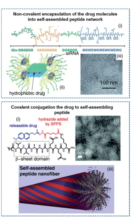
Depending on the design of the PA molecules, it is also possible to obtain spherical nanostructures in addition to the one-dimensional architectures. The use of β-sheet breaking triproline residues instead of trileucine residues on the PA design change the direction of the hydrogen bonding and resulted the formation of spherical nanostructures.[13] In other study, proline residues incorporated PA molecules were also developed to obtain spherical nanostructures as an efficient delivery vehicle for the oligonucleotides (ODNs).[54] Recently, the importance of nanostructure morphology in tuning immune response was also examined designing two different PA molecules consisting beta-sheet forming or breaking amino acid residues which coassembled into nanofiber or nanospherical architectures delivering ODNs (Figure 1.5).[55]
13
Figure 1.5 Schematic representation, CD spectra and AFM images of the design of the self-assembled K-PA nanofibers and P-PA nanospheres developed as the oligonucleotide (ODN) carriers to modulate immune response. (Adapted from Ref. 55 with permission from Nature Publishing Group)
14
1.3.3 Peptide Containing Other Hybrid Systems
Thanks to the organic chemistry, it is possible to obtain peptide hybrid systems composed of different chemical blocks besides peptides such as lipids, polymers, nucleobases, saccharides, aromatic groups, halogenic elements etc. Table 1.1 lists the self-assembled forms of recently reported hybrid peptide systems and gives additional information about regarding the structural properties. Peptides have been modified not only by changing the type of amino acid or order of its sequence, but also by using capping molecules at N- or C- terminus or by inserting a linker between peptide domains both to rationalize the self-assembly behavior and control the resultant structural features of formed assemblies.[56-58]
Table 1.1 Recently reported self-assembling peptide hybrid systems
Hybrid system Structure Ref.
Fmoc-FF, Fmoc-FG, Fmoc-GG, Fmoc-GF Nanoribbon/fiber/sheet [59] Fmoc-n-X-Phe
(n=2, 3 or 4 and X= F, Cl or Br) Fibril [60]
Fmoc-3-F-Phe-X and Fmoc-F5-Phe-X (X=OH,
NH2 or OMe) Fibril [61] Naphthalene-FF-taurine Nanotube [62] Phenothiazine-GFFY Nanofiber [63] Pyrenebutyryl-ɛ-Ahx-VVAGH-Am Nanofiber [64] Boc-FF Nanosphere [65] E3-X-G-perylene diimide-G-X-E3 (X= A3 or DA3) Nanofiber/fiber bundle [66]
Terthiophene-XE (X=G,V,I and L) Nanosheet/nanotube [67] DXX-quaterthiophene-XXD (X=G,A,V,I,F) Nanofiber [68]
Trigonal WTW Nanosphere/nanofiber [69]
mPEO7-F4-OEt Nanotube [70]
PEG-Pep-fluorophore-Pep-PEG Micelle [71]
CREKA-PEG2000-DSPE Micelle [72]
KK(K-hepta thymine-K)G3A3K(-OC16H31)-Am Nanofiber [73]
C18H35O-CTGACTGA-E4-Am Micelle [74]
15
Using aromatic moieties at the N-terminus of the peptide is another strategy to drive the self-assembly by providing amphiphilicity to the structure. Unlike the assembly mechanism of aliphatic peptide amphiphiles, aromatic group dominantly directs the self-assembly by its planar structure and resulting geometric restrictions due to the preferred stacking arrangements.[76] Various dipeptide combinations were exploited along with Fmoc (9-fluorenylmethoxycarbonyl) unit.[77-81] In a study, it was examined the self-assembly behavior of Fmoc-dipeptides composed of the combination of phenylalanine and glycine residues and revealed that the flexibility of the overall structure as well as the resultant conformation were affected from the amino acid type and sequence, leading to the formation of structurally different assemblies.[59]
Besides Fmoc-dipeptides, Fmoc-tripeptides together with tetra- and pentapeptide derivatives were also presented which exhibited nanofibrous or nanotubular structures.[82-85] In addition to the well-studied Fmoc group; naphthalene,[62, 86] phenothiazine,[63] pyrene,[64] carboxybenzyl,[87] azobenzene,[88, 89] naproxen[90] and benzimidazole[91] moieties were also utilized as aromatic capping at the N-terminus facilitating the self-assembly. The incorporation of non-proteinogenic amino acid, taurine, and naphthalene into the peptide backbone resulted in the formation of nanotubes, nanofibers or nanoribbons depending on the assembly conditions such as temperature, sonication and pH.[62]
Peptide π-electron systems are another well-studied class of hybrid peptide systems whose self-assembled architectures revealed different photo physical, electrical and mechanical properties. π-electron systems can be integrated into peptide backbone in many different ways such as a side chain[92], a linker between two peptide
16
sequences[93] or a capping molecule at the N-terminus.[94] While designing a peptide/ π-electron building block, amino acid sequence/π-electron system pair should be selected carefully in terms of their energetic contributions to the self-assembly in order to form supramolecular structures with improved electron transport properties.[95, 96]
Amphiphilicity in the hybrid structure can alternatively be achieved by anchoring hydrophilic polymers to hydrophobic peptide segments, or vice versa, through the different chemistries to afford copolymer conjugates of different structures.[97] The nature of the polymer, the chemical heterogeneity of the peptide, the conjugation site, and the reaction medium can affect the structure, dynamics and function of corresponding hybrid system. A number of polymer-peptide conjugates have been reported until now in which polymers with different composition, number, length of the side chains were used to create different form of nanostructures.[98, 99]
Similar to lipids, nucleobases or saccharides can also be conjugated to the peptides.[80] Peptide nucleic acid/peptide amphiphile conjugate was constructed on a solid support and poly-thymine PNA heptamer was built on the peptide amphiphile whose self-assembly resulted in the formation of uniform nanofibers.[73] Similar approach was later used to synthesize a series of peptide nucleic acid amphiphiles (PNAA) containing different hydrophobic and hydrophilic moieties.[74] The self-assembly driven mainly by the base pair stacking of PNAA duplexes and intermolecular noncovalent interactions led to the formation of spherical micelles. Saccharide incorporated peptide conjugates were also developed in recent years, affording uniform self-assembled nanostructures. They can be synthesized through diverse synthetic approaches: by using glycosylated amino acid,[100] directly
17
conjugating to peptide backbone or amino acid side chain through amide bond formation,[101] or selecting proper linker for the anchorage.[102, 103]
1.4 Characterizations of Self-Assembled Peptide Based Materials
Characterizations of self-assembled nanoscale architectures require sophisticated techniques due to their complex and dynamic nanoscale nature of the materials. The integration of the knowledge on material characterization with the developments on nanotechnology enable us advance tools and approaches to examine chemical, physical, electrical and mechanical properties of the self-assembled peptide based nanostructures at nanometer and atomistic scales (Figure 1.6). Understanding of material and intrinsic characteristics of these architectures at nanoscale is quite important to determine applicability of the nanostructures for desired purposes and the limitations which can be improved via superior design and fabrication strategies.
Figure 1.6 Common characterization techniques for variety of self-assembled peptide nanostructures
18
1.4.1 Spectroscopic Techniques
Spectroscopic methods are used to understand chemical and physical characteristics of the nanoscale peptide organizations focusing on the bond properties, vibrations, covalent and non-covalent interactions between the molecules. Although the basic principles of the spectroscopic techniques rely on the detection of the transitions on the molecules such as nuclear spin, molecular vibrations or electronic states; the detection methods for these transitions become different depending on the radiation source.
Within these spectroscopic approaches, Nuclear Magnetic Resonance (NMR) spectroscopy is a powerful technique enabling the analysis of the peptide based architectures at both liquid and solid conditions.[104] The self-assembly mechanism of fluorenylmethyloxycarbonyl (Fmoc) protected peptides which organize into three dimensional networks have been studied via 1D proton and 2D Nuclear Overhauser NMR spectroscopy in liquid and sol-gel transition states, and the results pointed the importance of hydrophobic and intermolecular interactions during the hydrogel formation.[105] On the other hand, solution state NMR methods limit the characterization of more complex peptide assemblies in liquid environment with high resolutions. Magic-angle spinning solid-state NMR (ssNMR) spectroscopy overcome the limits of solution based NMR techniques enabling through-space interatomic distance and torsion angle measurements on isotopically labelled peptide molecules.[106-108] Recently, ssNMR measurements revealed the high resolution structural organization of the supramolecular peptide based nanocarrier (Figure 1.7)[109] and self-assembled monomorphic MAX1 fibrils within hydrogel network.[110]
19
Figure 1.7 The detailed structural model of a self-assembled peptide-based nanocarrier developed in the light of the solid-state NMR (ssNMR) experiments. (Reproduced from Ref. 109 with permission from American Chemical Society)
Infrared (IR) spectroscopy deals with the electromagnetic spectrum change of peptides due to molecular vibrations and conformational changes within Amide A (~3200-3300 cm-1), Amide I (~1600-1700 cm-1), Amide II (~1480-1580 cm-1) and Amide III
(~1200–1300 cm−1) bands in mid-infrared region.[111-113] The shifts in Amide I band
were analyzed to monitor the structural changes as a result of the peptide self-assembly which can be triggered via different factors such as UV irradiation[114], ultrasonication[115, 116], pH, ion addition or electrostatically driven. Especially, the peaks in Amide I bands which are correlated with C=O stretching of the self-assembled peptide nanostructures contribute to the analysis of parallel or antiparallel β-sheet[117, 118], α-helix, β-turn or random-coil secondary structure organization of the peptide assemblies. Attenuated Total Reflectance (ATR) mode also enable to characterize the self-assembled peptide nanostructures at the surfaces or within the solutions[119] without any pellet preparation or sample manipulation.[120] The collected ATR-FTIR
20
spectrum of the pentapeptide assemblies was reported to show the vibrational peaks associated with β-sheet secondary structure organization within Amide I band.[121] Similar to the vibrational IR techniques, the Raman scattering of the peptide assemblies assists the analysis of the structural properties in the help of the assigned modes of molecular bonds found in the peptide architectures.[122] However, conventional Raman spectroscopy lack the spatial resolution for the detailed characterizations of the peptide nanostructures due the low signal to noise ratios at dilute conditions; and different approaches have been developed to improve the scattering intensities for the analysis. The relatively low Raman signal of the peptide assemblies were also increased via Surface enhanced Raman scattering (SERS) using the localized surface plasmon resonances of the metallic clusters in liquid or solid environment.[123, 124] In addition to the surface enhancement, tip enhanced Raman scattering (TERS) enable the comprehensive characterization of the peptide nanostructures merging the scanning probe approach with vibrational spectroscopy.[125, 126]
The chiral biomolecules including DNA, proteins and peptides interact with right- and left-handed photons differently, and that difference generate non-zero Circular Dichroism (CD) signal depending on the conformation of the molecules.[127] CD spectroscopy provides the information about the secondary structure of the peptide assemblies[128], conformational changes due to pH change[129], chirality of the supramolecular peptide architectures[130] and also the interactions between toxic molecules[131] or metal ions[132] with self-assembling peptides at near and far UV region (180-320 nm). β-sheet organization of asymmetric self-neutralizing amphiphilic peptide wedges which enhances strong positive and negative peaks at 190
21
and 220 nm, respectively was reported as a result of CD analysis of the supramolecular assemblies.[133] Blue shifted CD spectra of the peptide assemblies with positive maximum at 195 nm and two negative maxima at around 205 and 218 nm showed the formation of the super-helical peptide assemblies.[134] The conformational differences such as twisting or disordered β-sheets in the assemblies can be detected via shift in the CD spectra due to the π–π* transitions within the peptide backbone.[129, 135]
The simulation studies focus on the peptide self-assembly and molecular organization strengthen the initial design parameters and give useful insights for the experimental findings.[136-140] Incorporation of the experimental results and the simulation outputs developed using different molecular dynamics (MD) simulation programs improve the knowledge on the structural properties of the peptide assemblies.[109, 141-145] In the literature, the successful candidates determined within 8000 different peptide molecules using computational approaches were synthesized and their supramolecular assemblies were characterized using different spectroscopic techniques.[146] The assembly characteristics of synthetic amyloid peptide fragment at different conditions were characterized via detailed 2D NMR spectroscopy and the structural model was developed in the light of both the experimental outputs and the molecular dynamics simulations.[147] In addition, the spectral simulations of IR, vibrational CD and Raman techniques were conducted for the conformational study of the various peptide assemblies to highlight aggregation and fibril formation behaviors.[148, 149]
22
1.4.2 X-Ray Techniques
X-Rays are high energy electromagnetic waves and their interactions (reflection, diffraction or scattering) with the self-assembled peptide nanostructures provide the valuable information for the determination of size, shape and structural orientation. X-Ray diffraction (XRD) patterns of self-assembled peptide nanostructures were used to determine packing parameters and molecular organization focusing on the non-covalent interactions between the building blocks.[150-152] In the literature, the peaks associated with the hydrogen bonding, π-π stacking and β-sheet secondary structure organization were reported; and the spacing between peptide molecules were estimated using the Bragg’s law.[153, 154] The crystalline organization and unit cell parameters of the self-assembled arginine-capped peptide bolaamphiphile nanosheets were revealed via XRD measurements in addition to the other characterization techniques.[18] On the other hand, the estimated structural parameters for the secondary structures could slightly change depending on the ordered and disordered degree of the peptide organization consisting different amino acids sequences to direct self-assembly. Besides the powder diffraction examples, the oriented nanofiber wide angle X-Ray scattering of isomeric tetrapeptide amphiphiles were performed on the peptide solutions loading into the quartz capillaries.[155] In another study, molecular organization of dipeptide assemblies and interatomic distances at gel state were determined using X-Ray fiber diffraction technique.[156]
Small angle X-Ray scattering (SAXS) eliminates the drawbacks of the powder diffraction and enables the analysis of disordered peptide assemblies without time consuming sample preparation steps in their native conditions based on the lower angle X-Ray scattering from 1° to 10°.[157, 158] In the literature, SAXS analysis of
23
arginine-capped peptide bolaamphiphile structures at liquid conditions revealed the nanosheet assembly with bilayer organization complementary to the other structural characterizations (Figure 1.8).[18] SAXS profiles of the oppositely charged PAs mixtures prepared at different ratios underlined the formation of bilayers after thermal treatment process.[159] In another study, self-assembly of the maspin-mimetic PA into a mixture of cylindrical and ribbon-like shapes were characterized based on the analysis of the scattering data in Guinier region.[160]
Figure 1.8 The scattering (a) and electron density (b) profiles of the self-assembled arginine-capped peptide bolaamphiphile assemblies prepared at different concentrations and the fitting lines of the model according to a bilayer form factor. (Reproduced from Ref. 18 with permission from American Chemical Society)
24
1.4.3 Imaging Techniques
Starting with the development of Transmission Light Microscopy (TEM) in 1930s, microscopic approaches became a fundamental way to understand the structural and material properties at nanoscale. Advances in microscopic tools enhanced the visualization of the peptide based materials using different imaging techniques including TEM, Atomic Force Microscopy (AFM), scanning electron microscopy (SEM), fluorescence and other microscopies at high resolutions.
Conventional TEM imaging of the peptide based nanostructures requires special sample preparation procedures including staining via heavy metal salt such as uranyl acetate and drying of the sample before the imaging.[161] In the literature, a variety of TEM images of the self-assembled peptide architectures including nanofibers, nanospheres, nanobundles, nanotubes, helices etc. were reported and the details of the sample preparation procedures were supported.[54, 55, 162, 163] Although TEM imaging is the crucial way to show the structural properties of the peptide nanostructures, the effects of drying and staining steps on the peptide organization cannot be disregarded. On the other hand, cryogenic TEM (cryo-TEM) in which the sample is vitrified using special tools overcomes the sample preparation limits and enable to image peptide nanostructures at their native conditions.[32, 164, 165] The direct structural analysis of the dimeric α-helical coiled coils within the de novo designed self-assembling fiber system was performed via incorporation of the cryo-TEM imaging with image processing.[166] In another study, the effect of salt concentration on the morphology of the self-assembled amyloid peptide assemblies has been showed via cryo-TEM, and the results pointed the formation of flat ribbons
25
and decrease of twisted fibrils due to the salt screening of electrostatic interactions between the peptide molecules.[167]
AFM facilitates in situ visualization of the self-assembly process of the variety of peptide building blocks into supramolecular nanostructures with nanoscale resolutions at liquid conditions.[168] The monitoring of the structural changes depending on the environmental factors including pH, ion effect, temperature, concentration etc. is also possible via time-lapse AFM procedures. In the literature, AFM imaging was performed to monitor time dependent changes of the resilin-elastin-collagen-like chimeric polypeptide assemblies incubated in water at 50 °C.[169] Right-twisted helical ribbon formation and their conversion to microcrystals of amyloid derived peptide fragment, ILQINS hexapeptide, which is normally found as left-handed helical ribbon and nanotube organization in lysozyme, has been showed via AFM imaging at different time periods at room temperature.[170]
Direct observation of the peptide self-assembly is also possible via covalent conjugation of the fluorescence probes to the peptides using fluorescence imaging techniques.[171] Stochastic imaging and deconvolution methods were also used to decrease resolution limits and monitor the supramolecular peptide organization at nano scales. Additionally, the intrinsic fluorescence properties of the peptide nanostructures were also used for the imaging of the assemblies via confocal microscopy without any probe conjugation.[172, 173]
Without any staining or probe conjugation, chemical and spatial information collected via Raman spectroscopy enhanced the stochastic imaging of the biological samples.[174, 175] The self-assembled amyloid inspired peptide assemblies were imaged using SERS blinking effect during the in situ Raman spectrum measurements
![Figure 2.3 a) AIP-1; [M-H] - (calculated): 752.33, [M-H] - (observed): 752.33. b) RP- RP-HPLC chromatogram of the AIP-1, the change of response units with respect to time at 220 nm](https://thumb-eu.123doks.com/thumbv2/9libnet/6011575.126691/84.892.183.771.228.539/figure-calculated-observed-hplc-chromatogram-change-response-respect.webp)