SELF-ASSEMBLED PEPTIDE NANOSTRUCTURES AS A
VERSATILE TOOL FOR FABRICATION OF NANOSTRUCTURED
MATERIALS
A DISSERTATION SUBMITTED TO
THE GRADUATE SCHOOL OF ENGINEERING AND SCIENCE OF BILKENT UNIVERSITY
IN PARTIAL FULFILLMENT OF THE REQUIREMENTS FOR THE DEGREE OF
DOCTOR OF PHILOSOPHY IN
MATERIALS SCIENCE AND NANOTECHNOLOGY
By
Ruslan Garifullin January, 2015
ii
SELF-ASSEMBLED PEPTIDE NANOSTRUCTURES AS A
VERSATILE TOOL FOR FABRICATION OF
NANOSTRUCTURED MATERIALS
By Ruslan GarifullinJanuary, 2015
We certify that we have read this thesis and that in our opinion it is fully adequate, in scope and in quality, as a dissertation for the degree of Doctor of Philosophy.
Assoc. Prof. Dr. Mustafa Özgür Güler (Advisor)
Prof. Dr. Engin Umut Akkaya
Assist. Prof. Dr. Emrah Özensoy
Assoc. Prof. Dr. Gökhan Demirel
Assist. Prof. Dr. Necmi Bıyıklı
Approved for the Graduate School of Engineering and Science
Prof. Dr. Levent Onural Director of the Graduate School
iii
ABSTRACT
SELF-ASSEMBLED PEPTIDE NANOSTRUCTURES AS A
VERSATILE TOOL FOR FABRICATION OF NANOSTRUCTURED
MATERIALS
Ruslan Garifullin
Ph.D. in Materials Science and Nanotechnology Advisor: Assoc. Prof. Dr. Mustafa Özgür Güler
January, 2015
Several peptides such as amyloid like peptides (ALPs) and peptide amphiphiles (PAs) were synthesized by solid phase peptide synthesis technique. These peptides were utilized in fabrication of nanostructured materials. ALPs with amino (Ac-KFFAAK-Am) and carboxylate (Ac-EFFAAE-Am) functional groups were used in growth of titanium dioxide (titania) in solution. On the other hand, PA with amino group (lauryl-VVAGK-Am) was used in growth of titania by atomic layer deposition method. Obtained nanostructured titania in each case was used in construction of dye-sensitized solar cells.
Peptide amphiphile with phytochelatin mimetic sequence and adamantyl functionality (ADAc-6-Ahx-GECECECG-Am) was used in noncovalent functionalization of electrospun hydroxypropyl-β-cyclodextrin (HPβCD) mesh; HPβCD mesh functionalized with peptide was further used in metal ion scavenging. PA with sequence lauryl-VVAGH-Am was used in noncovalent encapsulation of zinc phthalocyanine derivative. New photophysical properties of encapsulated chromophore were studied and ultrafast energy transfer was observed. L and D peptide amphiphiles (L/D-pyrenebutyryl-6-Ahx-VVAGH-Am and L/D-lauryl-VVAGH-Am) were used to induce chiral organization of achiral chromophore (pyrene) in self-assembled nanofibers of PAs. Two strategies were involved to induce chiral organization: first strategy envisioned conjugation of pyrene to peptide sequence, whereas second strategy involved direct encapsulation of the
iv
chromophore. Achiral pyrene molecules organized in supramolecular chiral manner were observed to demonstrate circular dichroism.
Keywords: peptide, bio-inspired mineralization, nanostructured materials, programmed self-assembly, one-dimensional nanostructures, template directed synthesis, nanotechnology.
v
ÖZET
KENDİLİĞİNDEN DÜZENLENEN PEPTİT NANOYAPILARIN
NANOMALZEME ÜRETİMİNDE ÇOK YÖNLÜ KULLANILMASI
Ruslan Garifullin
Malzeme Bilimi ve Nanoteknoloji Programı, Doktora Tez Danışmanı: Doç. Dr. Mustafa Özgür Güler
Ocak, 2015
Amiloid benzeri peptit (ABP) ve peptit amfifil (PA) gibi çeşitli moleküller katı faz peptit sentezi tekniğiyle sentezlenmiştir. Bu peptitler, nanoyapılı malzeme üretiminde kullanılmıştır. Amino (Ac-KFFAAK-Am) ve karboksilat (Ac-EFFAAE-Am) fonksiyonel grupları taşıyan ALP’ler solusyonda titanya büyütmek için kullanılmıştır. Ayrıca, amino grup taşıyan PA (loril-VVAGK-Am) atomik katman kaplama yöntemiyle titanya büyütmek için kullanılmıştır. İki yöntemle de elde edilmiş olan nanoyapılı titanya, boya duyarlı güneş hücreleri yapımında kullanılmıştır.
Sekansıyla fitokelatini taklit eden ve adamantil fonksiyonel grubu taşıyan peptit amfifil (ADAc-6-Ahx-GECECECG-Am), elektro lif çekimi yöntemiyle üretilmiş hidroksipropil-β-siklodekstrin (HPβCD) ağını kovalent olmayan bir yolla fonksiyonelleştirmek için kullanılmıştır. Peptitle fonksiyonelleştirilmiş HPβCD ağı sonrasında sudan metal iyonlarının uzaklaştırılmasında kullanılmıştır.
loril-VVAGH-Am sekanslı peptit, çinko ftalosiyanin türevini kovalent olmayan yolla enkapsüle etmek için kullanılmıştır. Enkapsüle olmuş kromoforun yeni fotofiziksel özellikleri incelenerek, ultrahızlı enerji transferi gözlemlenmiştir. L ve D PA’lar (L/D-pirenbutiril-6-Ahx-VVAGH-Am ve L/D-loril-VVAGH-Am), akiral kromoforun (piren), kendiliğinden oluşan PA fiberlerinin içinde kiral düzenlenmesini tetiklemek için kullanılmıştır. Bunun için iki yol izlenmiştir: Birinci yol, pirenin peptit sekansına konjuge edilmesini esas alırken, ikinci yolda ise, kromoforun doğrudan enkapsüle edilmesi sözkonusuydu. Supramoleküler bir şekilde, kiral olarak
vi
düzenlenmiş akiral piren moleküllerinin dairesel dikroizm sinyali sergilediği gözlemlenmiştir.
Anahtar Kelimeler: peptit, biyo-esinlenme mineralizasyon, nanoyapılı malzemeler, kendiliğinden programlı düzenlenme, tek-boyutlu nanoyapılar, kalıp güdümlü sentez, nanoteknoloji.
vii
Acknowledgement
I would like to acknowledge everyone who has contributed to my PhD study and to my maturation as an independent researcher. Especially, I would like to thank my PhD advisor Dr. Mustafa Özgür Güler for his constant guidance and experience transfer. I am sincerely grateful to Dr. Necmi Bıyıklı, Dr. Ali Kemal Okyay and Dr. Emrah Özensoy for their active collaboration and fruitful discussions. I would like to thank my colleagues Handan Acar, Oya Ustahüseyin, Hakan Ceylan, Selman Turan Erkal, Mohammad Aref Khalily, Aslı Çelebioğlu, Levent Erdal Aygün, Berna Şentürk, Duygu Aydın and Hamit Eren for pleasant research time spend together. I am thankful to The Scientific and Technological Research Council of Turkey for BİDEB 2215 fellowship and TÜBİTAK 112M578 grant.
I am immeasurably indebted to my family which has constantly supported and encouraged me during my PhD study.
viii
Contents
ABSTRACT ... iii ÖZET ... v Acknowledgement ... vii Contents ... viii List of Figures ... xi List of Tables ...xx Chapter 1. ... 11. Introduction: Peptide synthesis and programmed assembly codes ... 1
1.1 Solid Phase Peptide Synthesis ... 2
1.2 Programmed assembly codes ...11
1.2.1 Electrostatic Interactions ...12
1.2.2 Coordination Interactions ...15
1.2.3 Hydrogen Bonding...18
1.2.4 π-π interactions ...22
1.2.5 Solvophobic interactions ...24
1.2.6 Van der Waals interactions ...29
Chapter 2. ...30
ix
2.1 Amyloid-like peptide nanofiber templated titania nanostructures as dye
sensitized solar cell anodic materials...30
2.1.1 Introduction ...30
2.1.2 Results and Discussion ...32
2.1.3 Conclusion ...45
2.2 Atomic layer deposition of titania on peptide amphiphile nanonetworks for dye sensitized solar cells ...46
2.2.1 Introduction ...46
2.2.2 Results and discussion ...47
2.2.3 Conclusion ...64
Chapter 3. ...65
3. Noncovalent functionalization of a nanofibrous network with a bio-inspired heavy metal binding peptide ...65
3.1 Introduction ...65
3.2 Results and Discussion ...67
3.2 Conclusion ...86
Chapter 4. ...87
4. Peptide amphiphile-chromophore interactions ...87
4.1 Encapsulation of a zinc phthalocyanine derivative in self-assembled peptide nanofibers ...87
x
4.1.2 Results and Discussion ...88
4.1.3 Conclusion ... 107
4.2 Induced helical chirality in peptide amphiphile systems ... 108
4.2.1 Introduction ... 108
4.2.2 Results and Discussion... 109
4.2.3 Conclusion ... 126
Chapter 5. ... 127
5. Conclusion and Perspectives ... 127
xi
List of Figures
Figure 1.1. Rink amide resin, Fmoc protecting group is shown in blue color. ... 5 Figure 1.2. Benzotriazole based coupling reagents (activators). ... 8 Figure 1.3 Schematic representation of two-stranded, α-helical coiled coils formed
by the dimerization of 35 residue sequences. ...13 Figure 1.4. Peptide RADA16-I. a. Amino acid sequence and molecular model of
peptide, b. AFM image of peptide nanofiber, and c. 0.1 wt% hydrogel in TRIS buffer at pH 7.5. ...14 Figure 1.5. TEM images of nanofibers of a. 1 at acidic pH, b. 2 at basic pH, and c.
co-assembled 1 and 2 at neutral pH. ...15 Figure 1.6. Interfacial metal ions in natural and engineered protein assemblies.
a. Representative examples of multimeric proteins that contain interfacial metals as catalytic sites: dicamba monooxygenase and MoFe-protein from nitrogenase. Symmetric protein subunits are shown as colored ovals, and black spheres represent interfacial metal sites. b. Protein complexes containing structural metal sites in their interfaces: voltage-gated potassium channel and insulin. c. A
schematic representation of metal-mediated peptide/protein assembly. ...16 Figure 1.7. Examples of metal-mediated peptide assemblies. a. A trimeric
coiled-coil peptide housing a structural Hg(II), and a catalytic Zn(II) site.27 b. A homodimeric triple helix protein scaffold with two redox-active 4Fe-4S clusters bound at interfacial positions.28 c. A membrane-soluble four-helix peptide assembly bearing two Fe-diphenylporphyrin cofactors in its interior.29 d. Cd(II)-mediated conformational switching of a peptide with heptad-repeat motifs
xii
between nanofibrils and discrete three-helix bundles (yellow: Cys-containing heptads and red: Cys-free heptads).30 e. Metal-dependent assembly of collagen bundles functionalized with complementary coordination motifs into banded architectures. ...17 Figure 1.8. H-bonding based structural motifs. a. Antiparallel and parallel pleated β-sheets and b. α-helix...19 Figure 1.9. a. A structural formula of the circular peptide. b. A representation of
self-assembled tubular nanostructure. c. TEM image of self-assembled nanotubes. ...20 Figure 1.10. a. DNA origami shapes. a. star, b. disk with three holes; c. triangle
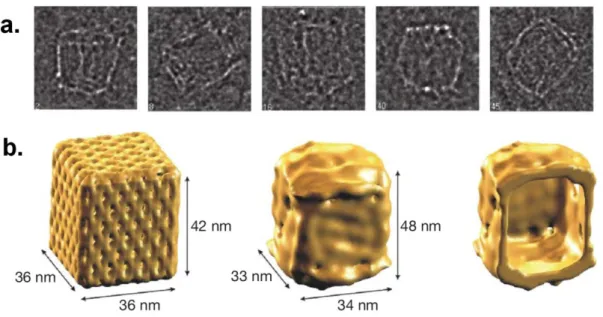
with rectangular domains, d. sharp triangle with trapezoidal domains and bridges between them. ...21 Figure 1.11. a. Single-particle cryo-TEM images of box-shaped ensembles. b.
Single-particle reconstruction of the DNA box applying D2 symmetry. Left, theoretical model. Middle, surface representation of the cryo-TEM map. Right, cut-open view showing the interior cavity of the cryo-TEM map. ...21 Figure 1.12. A peptidic molecule assembles into fibers and forms a gel in THF. ....22 Figure 1.13. A schematic representation of assembly of chiral nanocolumns. ...23 Figure 1.14. An assembly of oligopeptide-flanked bithiophene into nanofibers. ...24 Figure 1.15. a. Phosphatidylcholine molecule. b. Supramolecular architectures
formed by phosphatidylcholine. ...25 Figure 1.16. Amphiphilic low molecular weight gelators. ...28
xiii
Figure 2.1. Mass spectrum of Ac-KFFAAK-Am (Peptide-1) molecule. MS: (m/z)
calculated 751.4381, [M+H]+ found 752.4500, [M+2H]+2/2 found 376.7301. ...34
Figure 2.2. Liquid chromatogram of Ac-KFFAAK-Am peptide. ...34
Figure 2.3. Mass spectrum of Ac-EFFAAE-Am (Peptide-2) molecule. MS: (m/z) calculated 753.3334, [M-H]- found 752.4039, [M-2H]-2/2 found 375.7135. ...35
Figure 2.4. Liquid chromatogram of Ac-EFFAAE-Am peptide. ...35
Figure 2.5. Amyloid-like peptides. a. KFFAAK-Am (peptide 1), b. Ac-EFFAAE-Am (peptide 2), c. TEM image of the peptide 1 nanofibers, d. TEM image of the peptide 2 nanofibers. ...37
Figure 2.6. One-dimensional titania nanostructures after calcination. TEM images of peptide 1-templated titania a. nanotube network and c. nanotubes; TEM images of peptide 2-templated titania b. nanowire network and d. nanowire. ...38
Figure 2.7. XRD spectra of template-free TiO2 (black), peptide 1-templated TiO2 (blue), peptide 2-templated TiO2 (red) powders. ...40
Figure 2.8. Representative J–V spectra of devices based on peptide 1 (Pep-1), peptide 2 (Pep-2) templated and template-free TiO2 materials. ...42
Figure 2.9. Diffuse reflectance spectra of TiO2 materials. ...43
Figure 2.10. Structural formula of lauryl-VVAGK-Am peptide amphiphile. ...48
Figure 2.11. Mass spectrum of the lauryl-VVAGK-Am peptide amphiphile. Calculated m/z is 653.4840 (M), found m/z is 654.4798 (M+H) and 1307.9487 (2M+H). ...48
Figure 2.12. Liquid chromatogram of lauryl-VVAGK-Am peptide amphiphile. ...49
Figure 2.13. SEM image of crytical point dried gel on FTO (6 nm Pd/Au). ...50
xiv
Figure 2.15. EDX spectrum of templated TiO2 surface. ...53
Figure 2.16. SEM image of calcined ALD-coated TiO2 nanonetwork. ...54
Figure 2.17. EDX spectrum of templated TiO2 surface after calcination. ...55
Figure 2.18. XRD spectra of amorphous TiO2, anatase TiO2 and Si. ...56
Figure 2.19. Raman spectrum of anatase TiO2. ...57
Figure 2.20. TEM image of TiO2 nanotubes. ...58
Figure 2.21. Representative photoanode. Nanostructured TiO2 on FTO after calcination. ...60
Figure 2.22. Cross-sectional view of anatase TiO2 nanonetwork layer. ...61
Figure 2.23. Structural formula of N719 dye – a Ru(II)-based sensitizer. ...62
Figure 2.24. J-V curve of the DSSC devices with templated TiO2 (red) and with template-free thin layer TiO2 (black). ...63
Figure 3.1. a. Chemical structure of PMP. b. Mass spectrum of PMP after substracting mass spectra of water sample at that time interval. Mass data [M] (calculated) =1116.43; [M-H]- (observed) = 1115.37. c. Liquid chromatogram of PMP after dialysis. ...68
Figure 3.2. a. SEM image of electrospun CDNF. b. A macroscale photographic image of CDNF. c. Water-insoluble nature of CDNF. ...71
Figure 3.3. a. ITC curve obtained from titration of β-CD with adamantane conjugated peptide molecule. b. Schematic representation of interaction between β-CD and the peptide molecule. Adamantyl moiety of peptide molecule formed an inclusion complex with β-CD. The PMP molecule can bind to β-CD present in CDNF network. ...72
xv
Figure 3.4. SEM images of PMP-CDNF. a. before and after incubation in b. Cd(II), c. Ni(II) and d. Cr(VI) solutions (scale bars: 10 µm). ...74 Figure 3.5. XPS spectra of a. CDNF and b. PMP-CDNF. Insets show N1s (red line)
and S2p (blue line) XPS specta. After PMP-CDNF complex is formed, N1s and S2p peaks are present in XPS spectrum of PMP-CDNF c. FTIR spectrum of PMP, CDNF and PMP functionalized CDNF. Inset indicates red shift in PMP-CDNF spectra compared to CDNF spectra from approximately 3440 cm-1 to 3408 cm-1.75 Figure 3.6. a. Raman spectra of CDNF, PMP-CDNF and PMP-CDNF after
incubation with different metal solutions and mixture of the metal solutions. As amide I band at 1650 cm-1 and as –SH vibration at 510 and 2450 cm-1 was seen in PMP-CDNF. b. Raman spectral image at 2934 cm-1 of 100 µm x100 µm scan area of CDNF. ...77 Figure 3.7. a. Isothermal titration curve of PMP with CdCl2 solution b. Cd 3d XPS
spectrum of PMP-CDNF after incubation in CdII solution. c. Absorption change within 20 µM CdCl2 titration with PMP solution in 50 mM TRIS buffer at pH 8.0.
d. Isothermal titration curve of HPβCD molecule with CdCl2 solution. ...80
Figure 3.8. Isothermal titration curve of a. PMP and b. HPβCD molecule with Ni(NO3)2 solution. c. Absorption change in 20 µM Ni(NO3)2 titration with PMP
solution in 50 mM TRIS buffer at pH 8.0. d. XPS spectrum of PMP-CDNF after incubation in NiII solution. ...82 Figure 3.9. Isothermal titration curve of a. PMP and b. HPβCD molecule with
K2Cr2O7 solution. c. Absorption change in 20 µM K2Cr2O7 titration with PMP
solution in 50 mM TRIS buffer at pH 8.0. XPS spectra of d. PMP-CDNF after incubation in CrVI solution. ...83
xvi
Figure 3.10. The amount of metal ions a. Cd, b. Ni and c. Cr in µmol concentrations bound to per mg of the PMP-CDNF system and bare CDNF from different metal
solutions. ...84
Figure 4.1. Structural formula of lauryl-VVAGH-Am ...89
Figure 4.2. Mass spectrum of lauryl-VVAGH-Am. ...90
Figure 4.3. Liquid chromatogram of lauryl-VVAGH-Am. ...90
Figure 4.4. Schematic representation of ZnPc (1) encapsulation in PA (2) nanostructures. ...91
Figure 4.5. a. TEM and b. SEM images of the ZnPc – containing PA nanostructures. ...94
Figure 4.6. a. EDX spectrum of peptide nanofiber surface. b. Scanned fiber. ...95
Figure 4.7. Singlet oxygen measurement of ZnPc in THF, DPBF in THF (control), ZnPc within PA in water, ZnPc and DPBF within PA in water. ...96
Figure 4.8. Frequency sweep rheology measurement of a. ZnPc-containing PA gel and b. PA only gel. ...97
Figure 4.9. Circular dichroism spectra of ZnPc with PA at pH 2, pH 5, and pH 8. 1) ZnPc+PA pH 2, 2) ZnPc+PA pH 5, 3) ZnPc+PA pH 8. ...98
Figure 4.10. Absorbance and fluorescence spectra of ZnPc with and without the PA molecules. ...99
Figure 4.11. a. UV-Vis, and b. emission spectra of ZnPc film. ... 101
Figure 4.12. Time evolution of the excited state absorption signal at 585 nm for ZnPc in aqueous media with PA at different pH values. ... 103
Figure 4.13. Transient spectra of ZnPc. a. In THF. In H2O with PA at b. pH 2, c. pH 5, and d. pH 8. ... 104
xvii
Figure 4.14. Pump-probe data as a function of time (y) and wavelength (x) for a. ZnPc in THF, b. for ZnPc peptide at pH 2, c. for ZnPc peptide at pH 5 and d. for
ZnPc peptide at pH 8. ... 105
Figure 4.15. Structural forlmula of pyrenebutyryl-ɛ-Ahx-VVAGH-Am (1), pyrenebutyryl-ɛ-Ahx-vvaGh-Am (1′), lauryl-VVAGH-Am (2), and lauryl-vvaGh-Am (2′). ... 109
Figure 4.16. Mass spectrum of pyrenebutyryl-ɛ-Ahx-VVAGH-Am. ... 111
Figure 4.17. Liquid chromatogram of pyrenebutyryl-ɛ-Ahx-VVAGH-Am. ... 111
Figure 4.18. Mass spectrum of pyrenebutyryl-ɛ-Ahx-vvaGh-Am... 112
Figure 4.19. Liquid chromatogram of pyrenebutyryl-ɛ-Ahx-vvaGh-Am. ... 112
Figure 4.20. Mass spectrum of lauryl-VVAGH-Am. ... 113
Figure 4.21. Liquid chromatogram of lauryl-VVAGH-Am. ... 113
Figure 4.22. Mass spectrum of lauryl-vvaGh-Am. ... 114
Figure 4.23. Liquid chromatogram of lauryl-vvaGh-Am. ... 114
Figure 4.24. TEM images of self-assembled nanofibers of 1(left) and 1′ (right). ... 116
Figure 4.25. Emission spectra of a. 1 and b. 1′ in H2O (blue) and in TFE (black). 117 Figure 4.26. CD spectra of self-assembled nanofibers of 1 and 1′ in H2O (0.333 mM). ... 118
Figure 4.27. CD spectra of a. 1 and 1′ directly in TFE (0.333 mM) and b. pre-assembled 1 and 1′ in TFE (0.333 mM). ... 119
Figure 4.28. Absorption spectra of nanofibers of 1 in H2O (blue) and 1 dissolved in TFE (black). ... 120
Figure 4.29. Absorption spectra of a) nanofibers of 1 and 1′ in H2O and b) of 1 and 1′ dissolved in TFE (pyrene absorption region)... 120
xviii
Figure 4.30. TEM images of nanofibers of 2 (left) and 2’ (right) with encapsulated pyrene. ... 122 Figure 4.31. CD spectra of pyrene in nanofibers of 2 and 2′ in H2O (pyrene region).
... 123 Figure 4.32. CD spectra of 2 and 2′ nanofibers with pyrene (β-sheet region). ... 123 Figure 4.33. CD spectrum of pyrene in THF (0.333 mM). ... 124 Figure 4.34. Emmision spectra of pyrene in nanofibers of 2 and 2′ in H2O (0.333
mM pyrene). ... 124 Figure 4.35. Emission spectrum of pyrene in THF (0.333 mM). ... 125 Figure 4.36. UV-Vis spectra of pyrene in THF and pyrene encapsulated in 2 in H2O.
xix
List of Schemes
Scheme 1.1. SPPS principles. ... 3 Scheme 1.2. Fmoc cleavage mechanism. ... 7 Scheme 1.3. Activation of α-carboxylic acid of N-urethane protected amino acid
residue and its consequent reaction with amino group. ... 9 Scheme 1.4. Rink Amide resin cleavage mechanism, R represents amino acid
sequence. ...10 Scheme 3.1. a. Schematic drawing of HPβCD molecules. b. Electrospun CDNF as a
water-insoluble support. c. CDNF support functionalization with the metal ion binding peptide via its adamantyl moiety. d. Metal ion scavenging by PMP molecules. e. Chemical structure and representative illustration of the peptide molecule and metal ion. ...69 Scheme 4.1. Encapsulation process. a. Chromophore introduction. b. Sonication
xx
List of Tables
Table 1.1. List of non-covalent interactions. ...11 Table 2.1. Parameters of representative DSSCs. ...44 Table 2.2. Relative efficiencies of different devices normalized to dye and titania
amounts. ...45 Table 2.3. Cell parameters of the devices in Figure 2.24. ...63 Table 3.1. Atom percentages in PMP-CDNF based on XPS spectra. ...85 Table 3.2. Atom weight percentages of PMP, CDNF, and CDNF treated with TCEP
and TRIS and PMP-CDNF in terms of CHNS-O analyzer. ...85 Table 3.3. Comparison of experimental and theoretical [C]/[S], [N]/[S], [H]/[S], and
[C]/[N] of PMP. ...85 Table 4.1. Non-linear absorption decay time constants for ZnPc samples under
1
Chapter 1.
1. Introduction: Peptide synthesis and programmed assembly
codes
Solid phase peptide synthesis method paved the way to simple and robust peptide synthesis. This technological leap made peptide chemisrty and related fields grow enormously fast. Nowadays, reserchers actively exploit designer peptides to achieve programmed assembly, and look for diverse applications of the peptide nanostructures.1
Solid phase peptide synthesis is a widely used method, which allows synthesizing long amino acid sequences with high yield. One of the variations of SPPS includes protection of N-terminus of an amino acid with 9-fluorenylmethoxycarbonyl (Fmoc) protecting group. Nowadays, Fmoc SPPS is the most widely used variation of peptide synthesis on a solid support.2 Peptide synthesis based on this method will be discussed in details in this chapter.
Programmed peptide self-assembly represents a field of study with enormous potential. Programmed assembly is based on non-covalent weak interactions which can be used as an input on a design level. Designed peptides can assemble into various supramoleculer architectures with specified complexity. Several examples of designed peptides will be presented throughout this chapter.
2
1.1 Solid Phase Peptide Synthesis
It is important to utilize a peptide synthesis method that results in a high product yield. In 1963, Robert Bruce Merrifield publishes a paradigm shifting manuscript3 on a solid phase peptide synthesis (SPPS). He achieves a synthesis of a tetrapeptide on a polymer support. His method circumvents drawbacks of solution phase peptide synthesis approaches and paves the way to high yield peptide synthesis, even for long amino acid sequences. A 100 amino acid sequences are in the reach of SPPS method. Development of a SPPS approach was a significant leap in synthetic peptide chemistry. Importance of this achievement was fully appreciated and in 1984 the Nobel Prize in chemistry was awarded to Robert Bruce Merrifield "for his development of methodology for chemical synthesis on a solid matrix". Moreover, Merrifield’s SPPS also permitted the development of automation4-6
and the extensive range of robotic instrumentation is now available. After defining a synthesis strategy and programming the amino acid sequence of peptides, machines can automatically perform all the synthesis steps required to prepare peptide samples. SPPS has now become the method of choice to produce long peptides and short proteins.7
The main idea of SPPS is a stepwise elongation of an amino acid sequence on a solid polymer support.8 The principles of SPPS are illustrated in Scheme 1. The N-protected C-terminal amino acid residue is tethered via its carboxyl group to a hydroxyl (or chloro) or amino resin to yield respectively an ester or amide linked peptide that will ultimately produce a C-terminal acid or a C-terminal amide peptide. After loading the first amino acid, the desired peptide sequence is assembled in a linear fashion from the C-terminus to the N-terminus (the CN strategy) by repetitive cycles of Nα deprotection and amino acid coupling reactions.
3
4
Side-chain functional groups of amino acids must be protected with permanent protecting groups (Pn) that are stable in the reaction conditions used in the process of peptide growth. The α-amino group is protected by a temporary protecting group (T) that is usually an urethane derivative. The temporary protecting group (T) can be easily removed under mild conditions that preserve peptide integrity and reduce the rate of epimerization, which can occur via 5(4H)-oxazolone formation of the activated amino acid. Ability of urethanes to prevent epimerization also explains the superiority of the CN strategy. After coupling, the reactant excess is removed by series of filtration and washings. Next, the removal of temporary N-terminal protecting group takes place, thus allowing the addition of the next N-urethane protected amino acid by activation of its α-carboxylic group. This deprotection/coupling cycle is repeated until the target sequence is obtained. Finally, the peptide is cleaved from the resin and the side-chain protecting groups are simultaneously removed.
In SPPS, two main strategies are utilized: Boc/Bzl and the Fmoc/tBu approaches for T/Pn protecting groups. The Boc/Bzl strategy makes use of the unequal acid lability of the side-chain protecting groups. In this approach, the Boc group is removed by pure TFA or TFA in dichloromethane, and side-chain protecting groups and peptide-resin bonds are cleaved at the end of the synthesis by treating the peptide-resin with a strong acid such as anhydrous hydrofluoric acid (HF). While this method results in efficient synthesis of large peptides and small proteins, the use of highly toxic HF and the need for special teflon-lined apparatus seriously limit the usability of this approach. Moreover, the strongly acidic conditions can cause deleterious and irreversible changes in the structure of peptides with sensitive sequences.
5
The Fmoc/tBu method utilizes an orthogonal protecting group strategy. This strategy uses the base-labile 9-fluorenylmethoxycarbonyl (Fmoc) group for protection of the α-amino functional group, acid-labile side-chain protecting groups and acid-labile peptide-resin linkers. The advantage of this strategy is that temporary and permanent orthogonal protecting groups are removed by different mechanisms, thus allowing the use of milder acidic conditions for final deprotection and peptide cleavage from the resin. For all these reasons, Fmoc-based SPPS technique2 is the method of choice for the routine peptide synthesis, and it is actively utilized in laboratories worldwide.
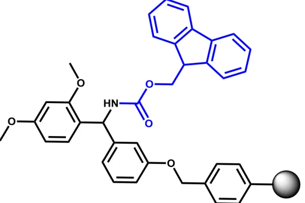
Figure 1.1. Rink amide resin, Fmoc protecting group is shown in blue color.
In the Fmoc/tBu method, general route to target peptide sequence comprises three main parts. First part is loading of a resin with the first Fmoc-protected amino acid. If
6
we consider a widely used Rink Amide resin (Figure 1.1),9 it is first required to remove Fmoc protecting groups of amino functionalities present on polymer support. Fmoc removal mechanism is depicted in Scheme 1.2; Fmoc removal is generally achieved by treatment of the resin with 20% (v/v) piperidine solution in DMF.2
7
8
After deprotection of the resin, the first amino acid can be loaded onto resin. For this purpose, Fmoc-protected amino acid needs to be activated. Several activators such as HBTU, HATU, HCTU, TBTU, PyBOP are utilized in the peptide synthesis (Figure 1.2).2 These coupling reagents resolve racemization issue and therefore, have effectively replaced carbodiimides. Activation of amino acid by HBTU and its consequent reaction with amino group are given in Scheme 1.3. Deprotonation of amino acid is generally achieved by organic base such as diisopropylethylamine (DIPEA). Loaded with the first amino acid resin becomes available for peptide construction.
9
Scheme 1.3. Activation of α-carboxylic acid of N-urethane protected amino acid residue and its consequent reaction with amino group.
Peptide construction is carried on with deprotection/coupling cycles until desired sequence is obtained (Schemes 1.1-1.3). When desired sequence is synthesized, it is cleaved from the resin by a concentrated TFA (~95%). Peptide cleavage mechanism is given in Scheme 1.4. Side-chain protecting groups are also cleaved under these highly acidic conditions. Side-chain group deprotection may yield highly active carbocations, which are generally suppressed by introduction of so-called “scavengers” into cleavage mixture. Standard scavengers are triisopropylsilane (TIS) and water (H2O) molecules.2
10
Scheme 1.4. Rink Amide resin cleavage mechanism, R represents amino acid sequence.
11
1.2 Programmed assembly codes
Peptides are actively used as building blocks for supramolecular nanostructures such as nanofibers, nanotubes, nanovesicles, nanoribbons and etc.10 By controlling sequence it is possible to establish a relative control over morphology of a target nanostructure and thus achieve programmed assembly.11 Moreover, it is possible to obtain nanostructures with appropriate functionalities on the surface of the structures. There are several inputs on a design level that allow controlling an assembly process. These inputs are based on weak noncovalent interactions such as electrostatic interactions, coordination binding, hydrogen bonding, π-π interactions, solvophobic effects and van der Waals interactions (Table 1.1).12
Table 1.1. List of non-covalent interactions.12
Type of Interaction Strength (kJ/mol) Range Properties
Electrostatic 50-300 long Non-selective
Coordination binding 50-200 short Directional
Hydrogen bonding 5-120 short Selective, directional
π-π interaction 0-50 short Directional
Solvophobic Depends on solvent type short Directional constraint
van der Waals < 5 short Non-directional,
non-selective
Covalent* 350 short Irreversible
12 1.2.1 Electrostatic Interactions
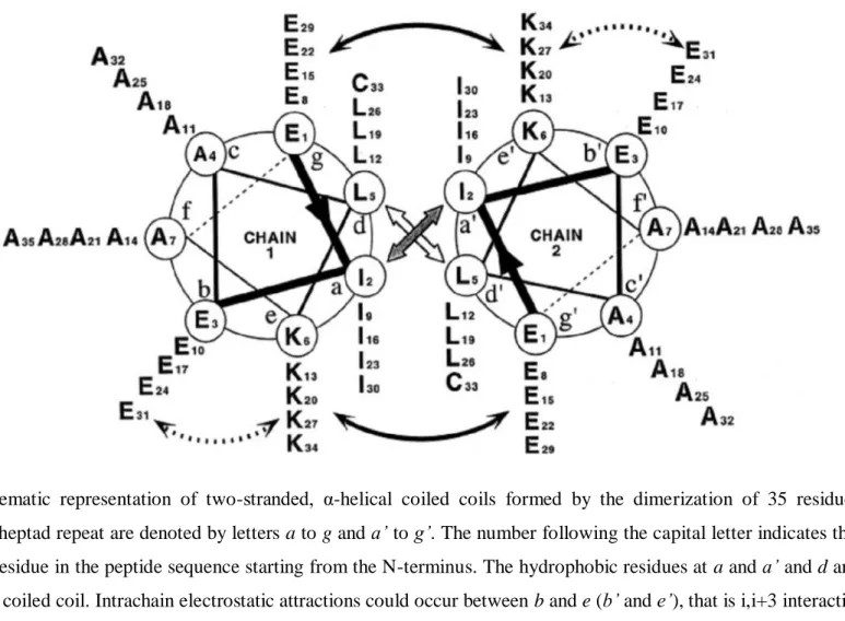
Electrostatic interaction is a Coulomb-type interaction between electrically charged species. Electrostatic interactions play crucial role in formation of quaternary structure of proteins and have profound impact on protein functionality. Two protein domains or subunits can be brought and hold together by electrostatic interactions.13 This kind of interaction can be used to bring together short peptides and thus trigger assembly processes. There are many studies that utilize this kind of input to direct assembly process and fold peptide into certain morphology. Synthetic α-helical coiled coils are an example of nanostrucutres stabilized by electrostatic interactions (Figure 1.3). The amphipathic α-helical peptides are designed to dimerize by interchain hydrophobic interactions at positions a and d and interchain salt bridges between lysine and glutamic acid residues at positions e and g of the repeating heptad sequence of Glu-Ile-Glu-Ala-Leu-Lys-Ala (g-a-b-c-d-e-f).14 Salt bridges formed between chains are an explicit example of designed electrostatic interactions.
13
Figure 1.3 Schematic representation of two-stranded, α-helical coiled coils formed by the dimerization of 35 residue sequences. Positions in the heptad repeat are denoted by letters a to g and a’ to g’. The number following the capital letter indicates the position of the amino acid residue in the peptide sequence starting from the N-terminus. The hydrophobic residues at a and a’ and d and d’ interact and stabilize the coiled coil. Intrachain electrostatic attractions could occur between b and e (b’ and e’), that is i,i+3 interactions, or e and b (e’ and b’), that is, i,i+4 interactions (dashed arrows). Interchain electrostatic attractions i,i’+5 (g-e’ or g’-e) are shown by the solid arrows (Reproduced from Ref. 14 with permission from American Chemical Society).
14
Another interesting example is an ionic self-complementary peptide RADARADARADARADA (RADA16-I) that forms a well defined nanofiber scaffold.15 This 16-residue peptide exhibits stable β-sheet organization and undergoes molecular assembly into nanofibers and eventually forms a hydrogel (Figure 1.4).
Figure 1.4. Peptide RADA16-I. a. Amino acid sequence and molecular model of peptide, b. AFM image of peptide nanofiber, and c. 0.1 wt% hydrogel in TRIS buffer at pH 7.5 (Reproduced from Ref. 15 with permission from National Academy of Sciences of the U.S.A.).
Next study suggests hydrogel formation by interaction of oppositely charged complimentary modules, Ac-KWKAKAKAKWK-Am and Ac-EWEAEAEAEWE-Am.16 Further, role of electrostatic interactions in gel formation is investigated by gradually converting glutamic acid residues (E) into glutamine residues (Q) and tracking changes in mechanical properties of a gel by dynamic rheology.
15
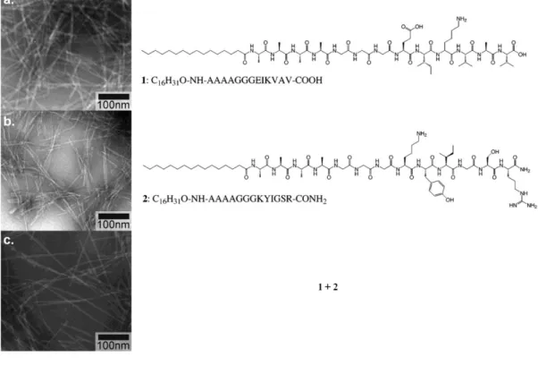
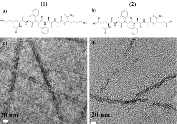
Aliphatic peptide amphiphiles17 is an interesting variation of peptide molecules where fatty acid is conjugated to N-terminal end. Peptide amphiphiles involve a number of non-covalent interactions in assembly process.18 Two oppositely charged peptide amphiphiles have been shown to assemble into nanofibers by electrostatic attractions in aqueous medium at neutral pH (Figure 1.5).19 Peptide assembly and nanofiber formation took place upon mutual charge screening of interacting peptides.
Figure 1.5. TEM images of nanofibers of a. 1 at acidic pH, b. 2 at basic pH, and c. co-assembled 1 and 2 at neutral pH (Reproduced from Ref. 19with permission from American Chemical Society).
1.2.2 Coordination Interactions
Engineered peptides and proteins can assemble in response to metal coordination (Figure 1.6).20 Peptides are attractive building blocks for systems assembling in
16
programmed manner because they are chemically stable, can be synthesized in large amounts and can be modified with unnatural functionalities at specific sites. The interplay between peptide assembly and metal coordination has been used to induce secondary/tertiary structure formation in short peptides,21-23 to construct artificial metalloenzymes24,25 and to direct the peptide assembly for binding biological targets.26
Figure 1.6. Interfacial metal ions in natural and engineered protein assemblies. a. Representative examples of multimeric proteins that contain interfacial metals as catalytic sites: dicamba monooxygenase and MoFe-protein from nitrogenase. Symmetric protein subunits are shown as colored ovals, and black spheres represent interfacial metal sites. b. Protein complexes containing structural metal sites in their interfaces: voltage-gated potassium channel and insulin. c. A schematic representation of metal-mediated peptide/protein assembly (Reproduced from Ref. 20with permission from Elsevier).
17
Figure 1.7. Examples of metal-mediated peptide assemblies. a. A trimeric coiled-coil peptide housing a structural Hg(II), and a catalytic Zn(II) site.27 b. A homodimeric triple helix protein scaffold with two redox-active 4Fe-4S clusters bound at interfacial positions.28 c. A membrane-soluble four-helix peptide assembly bearing two Fe-diphenylporphyrin cofactors in its interior.29 d. Cd(II)-mediated conformational switching of a peptide with heptad-repeat motifs between nanofibrils and discrete three-helix bundles (yellow: Cys-containing heptads and red: Cys-free heptads).30 e. Metal-dependent assembly of collagen bundles functionalized with complementary coordination motifs into banded architectures31 (Reproduced from Ref. 20with permission from Elsevier).
Previously mentioned α-helical coiled-coil peptides with heptad-repeats are the most widely used scaffolds in protein engineering, because their structures and assembly route can be programmed up to certain extent at the amino acid sequence design level.32,33 For instance, introverted hydrophobic residues (positions a and d) can be replaced with metal-coordinating residues to obtain internal coordination sites, at the
18
same time, extroverted residues can be modified for metal-directed supramolecular assembly. Several studies have shown that even multiple metal ions can be selectively introduced into assembling trimeric or tetrameric helical scaffolds. Some of the examples are assemblies with interfacial Cu (I/II),34 Ni(II)/Cu(II)35 and Hg(II)/Zn(II) (Figure 1.7a)27 mixed metal ion pairs, Cu(I)-thiolate36 or Cd(II)-thiolate clusters,37 and 4Fe-4S clusters (Figure 1.7b).28 All of the mentioned assemblies are constructed via appropriate spatial organization of histidine and cysteine residues. Regarding designer transmembrane protein complexes, the peptide sequence Ac-AIYGILAHSLASILALLTGFLTIW-Am assembling upon binding a pair of Fe(II/III) diphenylporphyrins into four-helix bundles has been reported (Figure 1.7c).29
1.2.3 Hydrogen Bonding
Hydrogen bonding (H-bonding) is inherent interaction mode of peptides and proteins. β-sheet and α-helix structural motifs38
(Figure 1.8) are the most abundant organizational elements in folding and supramolecular assembly of proteins. In polypeptides, mainly amide bonds which connect adjacent amino acids are responsible for emergence of structural H-bonding. H-bonding in tandem with engineered sequence can be used as an input on design level that will direct and determine the fate of assembling structure. H-bonding being weak on its own gains considerable weight when reaches cumulative effect, i.e. hydrogen bonds have additive nature.
19
Figure 1.8. H-bonding based structural motifs. a. Antiparallel and parallel pleated β-sheets and b. α-helix (Reproduced from Ref. 38 with permission from Thieme).
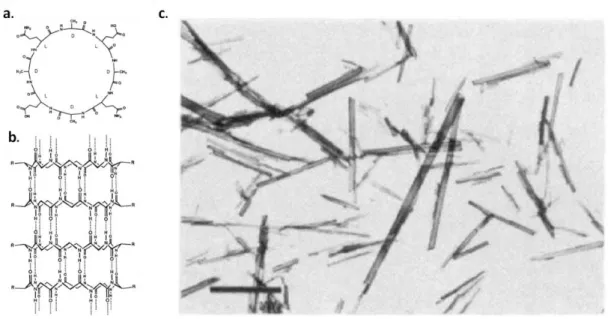
All peptide-based assembling materials in one way or the other involve hydrogen bond mediated interaction mode. In many of our aliphatic peptide amphiphile designs39-41 we have utilized VVAG sequence, which is strong β-sheet forming segment (Figure 1.8a). Active intermolecular hydrogen bond formation takes place between these four residues which actually “glue” assembling molecules together. Mentioned earlier coiled coil peptides involve intramolecular H-bonding, which is known as α-helix motif (Figure 1.8b). Next example includes assembly of ring-shaped peptide molecules into nanotube structures (Figure 1.9).42 A cyclic octapeptide with the sequence of cyclo[-(aEaQ)2-] forms antiparallel stacks via
intermolecular H-bonding along peptide backbone. Formation of contiguous β-sheet structure provides nanotube growth. Alternating L and D amino acids ensure that all side chains are situated on the exterior of the nanotubes.
20
Figure 1.9. a. A structural formula of the circular peptide. b. A representation of self-assembled tubular nanostructure. c. TEM image of self-assembled nanotubes (Reproduced from Ref. 42 with permission from Nature Publishing Group).
H-bonding is vital for DNA replication, transcription and translation, nucleobases adenine (A) and guanine (G) are complimentary with nucleobases thymine (T)/uracyl (U) and guanine (G), respectively. This kind of complimentarity provides highly selective recognition between polynucleotides. Probably the most striking example of H-bonding assisted polynucleotide assembly is so-called “DNA origami” approach. This approach allows programmed folding of a single-stranded DNA scaffold with oligonucleotides into two- and three-dimensional objects (Figures 1.10 and 1.11).43,44 Programmed assembly utilizes complementarity principle between nucleobases in polynucleotide chains; the nucleobases demonstrate highly selective H-bonding.
21
Figure 1.10. a. DNA origami shapes. a. star, b. disk with three holes; c. triangle with rectangular domains, d. sharp triangle with trapezoidal domains and bridges between them (Reproduced from Ref. 43 with permission from Nature Publishing Group).
Figure 1.11. a. Single-particle cryo-TEM images of box-shaped ensembles. b. Single-particle reconstruction of the DNA box applying D2 symmetry. Left, theoretical model. Middle, surface representation of the cryo-TEM map. Right, cut-open view showing the interior cavity of the cryo-TEM map (Reproduced from Ref. 44 with permission from Nature Publishing Group).
22 1.2.4 π-π interactions
π-π interactions are a widely used type of input in programmed assembly. π-rich systems can provide an extra structural motif and stabilize overall architecture. The strongest π-π interaction is stacking of aromatic moieties. Effective overlap between aromatic π-systems can significantly stabilize assembling structure, and thus, actively participate in assembly process.45 Several studies including our own have used this kind of input; for instance, diphenylalanine (FF) unit has taken place in several peptide designs. The simplest peptide of this kind which is dipeptide FF assembles into highly-ordered nanotubular structures.46 Peptide designs such as Ac-KFFAAK-Am and Ac-EFFAAE-Ac-KFFAAK-Am have been realized in our own studies;47,48 these peptides effectively assemble into fibrilar structures (Figure 2.5). Moreover, even a single amino acid – phenylalanine was reported to assemble into fibrils.49
Figure 1.12. A peptidic molecule assembles into fibers and forms a gel in THF (Reproduced from ref. 50 with permission from John Wiley & Sons Ltd).
A peptidic molecule (Figure 1.12) consisting of trimesic acid core (π–π stacking), Gly-Ala dipeptidic pendants (H-bonding), and long alkyl chains terminals (solvophobic interaction) is another example for π–π interaction stabilized
23
ensemble.50 These molecules with C3-symmetry undergo supramolecular polymerization in THF and form a gel.
Figure 1.13. A schematic representation of assembly of chiral nanocolumns (Reproduced from Ref. 51with permission from American Chemical Society).
A supramolecular chirality tuning of a π-conjugated molecule through cooperative π– π interaction and H-bonding was reported.51
A compound having molecular triblock structure, pyrene moiety at focal point, branched glutamic acids as chiral hydrogen-bonded parts, and lipophilic alkyl parts, was expected to form cylindrical pillars by nanosegregation between the molecular block structures (Figure 1.13).
24
Figure 1.14. An assembly of oligopeptide-flanked bithiophene into nanofibers (Reproduced from Ref. 52with permission from American Chemical Society). Next intriguing example represents a π-conjugated system flanked by oligopeptide sequence at each side (Figure 1.14).52 This molecule with embedded bithiophene unit assembles into discrete one-dimensional nanostructures in aqueous medium. π–π stacking of bithiophenes and H-bonding between oligopeptides give rise to programmed assembly. The peptide-based molecular design provides intimate π−π communication within the supramolecular ensemble upon charge screening. These nanostructures can be utilized in optical or electronic applications in biological environments.
1.2.5 Solvophobic interactions
Solvophobic interaction is an important mode of interaction which can be encountered in animal cells. Phospolipids such as phosphatidylcholines (Figure 1.15a) can assemble in aqueous medium due to hydrophobic effect. Phospholipid bilayer, liposome and micelle are explicit examples of supramolecular architectures formed as a result of solvophobic interactions (Figure 1.15b). Solvophobic aggregation is common for amphiphilic molecules. The solvophobic parts of the molecules tend to aggregate to minimize their surface area contacting the solvent, whereas the solvophilic parts try to remain solvated. Solvophobic aggregation takes
25
place mainly due to favorable entropy rather than enthalpy and is thought to be achieved in two stages. The stages are solvation and solvophobic escape from the solvent; in the later stage solvent molecules are liberated, and consequently total entropy is increased.
Figure 1.15. a. Phosphatidylcholine molecule. b. Supramolecular architectures formed by phosphatidylcholine.
Folding of globular proteins is also accompanied with solvophobic interactions.53 Hydrophobic residues in globular proteins tend to burry themselves in forming hydrophobic core, whereas hydrophilic residues tend to stay in contact with the solvent on the surface of a globe. For instance, hemoglobins from higher organisms
26
are multi-subunit globular proteins. Each subunit of the hemoglobin complex is a globular protein with an embedded heme group. These subunits are organized in characteristic three-dimensioanl globin fold typically consisting of eight α-helices; the folding process is primarily governed by sterics and hydrophobic interactions of the amino acid side chains near the helix interfaces. On the higher design level, the noncovalent interactions stabilizing the quternary structure of the complex comprise solvophobic interactions, van der Waals forces, H-bonding, and electrostatic interactions (salt bridges).
Many low molecular weight compounds can assemble and gel a solvent. Gel formation can be defined as an extensive solute precipitation into three-dimensional network which entraps a solvent. An assembly of these compounds into fibrous networks is driven by noncovalent interactions such as electrostatic interactions, π-π interactions, dipolar interactions, H-bonding, and van der Waals interactions. Solvophobic effects also play a crucial role. These solvophobic effects stem from moieties or functional groups in the gelator molecule that are poorly soluble in the solvent to be gelled, and contribute to the gel forming ability by reducing the overall solubility of the gelator in that solvent.
A large group of gelators is related to amphiphilic molecules (Figure 1.16). Amongst the oldest gelators known to humankind are metallic soaps.54 An example of a metallic soap gelator is the lithium salt of 12-hydroxystearic acid 1.55 This gelator assembles by means of several intermolecular interactions: ionic interactions between the metal ions, van der Waals interactions between the alkyl tails and H-bonding interactions between hydroxyl groups. Cationic surfactants are structurally
27
related to the metallic soaps. Quaternary ammonium salts with long alkyl chains, like compound 2 exhibit gel forming behavior due to association driven by electrostatic interactions, as well as the poor solubility of the quarternary ammonium head in many organic solvents.56 Less obvious amphiphilic gelators are compounds 3 and 4. Gelator 3 is a perfluorcarbon-hydrocarbon block-compound, of which in hydrocarbon solvents the perfluorocarbon block is insoluble and hence solvophobic, whereas the aliphatic part is soluble, and hence solvophylic.57 At room temperature compound 3 is immiscible with aliphatic hydrocarbons, leading to extensive precipitation and gel formation at weight concentrations as low as 2 %. Compound 4 can be also considered as an amphiphile for hydrocarbon solvents, with the aliphatic hydrocarbon and anthracene moieties as solvophylic and solvophobic parts, respectively.58 Apart from solvophobic effects aggregation of 4 is also governed by π-π stacking and van der Waals interactions. In addition to solvophobic effects and specific intermolecular interactions, structural rigidity may have its own contribution to the gelling potency. For example, many steroids like cholesterol molecule 5 efficiently gel various organic solvents.59,60 The strong aggregation behavior of these compounds is thought to stem from their molecular rigidity, which reduces entropic losses upon assembly. 1,3:2,4-di-O-benzylidene-D-sorbitol 6 is also a fairly rigid molecule with reduced conformational freedom, and it is known as an efficient gelator for both water and organic solvents.61,62
In the examples given above H-bonding is mostly absent or its contribution to assembly mechanism is minimal. However, for many gelator molecules H-bonding is essential for their ability to gel a solvent. For instance, the peptides like 7 have been reported to gel a range of different organic solvents, due to the strong H-bonding
28
between the peptide amide groups.63 Another well-known example of an amino acid based gelator is Fmoc-diphenylalanine 8, this aromatic peptide amphiphile is a very potent hydrogelator capable of gelling water at weight concentrations as low as 0.22%.64 With this compound again solvophobic effects, namely hydrophobic effects, and π-π interactions between the pendant benzyl groups make a major contribution to the stability of its supramolecular aggregates.
29 1.2.6 Van der Waals interactions
The van der Waals force is the attractive or repulsive force between molecules other than those due to covalent bonds or to the electrostatic interactions of ions. The van der Waals force originates from dipole or induced-dipole interactions at the atomic and molecular levels. There are three different types of van der Waals forces:
1. Keesom interactions: permanent dipole-permanent dipole interactions. 2. Debye interactions: permanent dipole-induced dipole interactions. 3. London dispersion forces: induced dipole-induced dipole interactions.
The van der Waals forces play crucial role in protein folding. Since atoms are in constant oscillation, the dipole induction is a continuous process. In comparison with other forces determining protein conformation, single van der Waals interactions are extremely weak. However, the large number of closely arranged van der Waals forces in proteins makes these interactions significant to the preservation of tertiary structure. Striking example of cumulative effect of van der Waals interactions is adhesion mechanism of gecko setae to various surfaces.65
Aliphatic and aromatic peptide amphiphiles mentioned earlier, once assembled, are also stabilized by van der Waals forces. Alkyl tails or aromatic moieties closely packed in hydrophobic core of nanostructures are effectively kept together by cumulative effect of van der Waals interactions.
30
Chapter 2.
2.
Peptide nanonetworks templated titania for dye sensitized
solar cell
2.1 Amyloid-like peptide nanofiber templated titania nanostructures as dye sensitized solar cell anodic materials
This work is partially described in the following publication:
Acar, H., Garifullin, R., Aygun, L.E., Okyay, A.K., Guler, M. O., “Amyloid-Like Peptide Nanofiber Templated Titania Nanostructures as Dye Sensitized Solar Cell Anodic Materials”, Journal of Materials Chemistry A, 2013,1, 10979
2.1.1 Introduction
Solar energy is an important source for sustainable energy efforts. Dye sensitized solar cells (DSSCs) are promising and inexpensive alternatives to silicon based solar cells.66 Although there are many semiconductor materials available for fabrication of DSSCs, titania (TiO2) is the most widely used one owing to its
several advantages such as abundance, biocompatibility, eco-friendliness and inexpensiveness.67 DSSCs have several components for light harvesting, electron transport, and hole transport. Optimization of each component affects the overall performance of the cell.68 Since electrons and holes are transported in different media, separate optimization in each interface can be studied to enhance the yield of DSSCs. There are several parameters to enhance the efficiency of DSSCs including TiO2 component such as obtaining pure anatase phase, greater surface
31
and well-connected network of individual nanostructures.69,70 On the other hand, application of TiO2 nanoparticles in DSSCs limits the power conversion
efficiency of DSSCs by electron trapping in the nanostructured film. The time scale for injection and transport of the electron by TiO2 is comparable with the
time scale of the recombination by the electrolyte.71 The competition between these time scales determines the photon-to-current conversion efficiency of the DSSC. One of the major problems of DSSCs is this loss of electron at the TiO2/electrolyte interface.72
The transport of charge carries through a one-dimensional morphology of TiO2
electrode is more facile because of its inherent nature to produce lower diffusion resistance.73 One-dimensional nanostructures including nanowires74 and nanorods75 are able to transport electrons before recombination process takes place.76 Highly ordered architectures offer longer electron diffusion paths and shorter electron transport time constants than randomly oriented titania nanoparticle films.77 In fact, cylindrical (nanowire) and tubular (nanotube) architectures act as a “box” that delimits medium through which electron travels. If the diameter of the “box” is smaller than the mean free path of the electron, enhancement in electron mobility could be expected.78
Proteins and peptides can assist synthesis of nanostructured inorganic materials in an eco-friendly strategy via biomineralization process. Nature inspired synthetic peptide nanofiber networks have wide applications including bioactive tissue scaffolds,79,80 carrier agents,81,82 and template-directed synthesis of inorganic materials.83 Self-assembled amyloid-like peptides (ALPs) can be successfully used to obtain one-dimensional inorganic nanostructures,47,84 which may find
32
applications in electronics85 and sensors.86 Synthesis of TiO2 hybrid nanowires
using amyloid protein fibrils as templates, and their application in hetero -junction hybrid solar cells were previously reported.87 The peptide assemblies can be effectively used as soft templates for synthesis of inorganic and organic-inorganic hybrid nanostructures.88 Previously, we demonstrated titania and silica mineralization on the self-assembled ALP templates.47
In this chapter, we demonstrate peptide nanofiber templated synthesis of TiO2
nanostructures. Bottom-up approach, realized through mineralization process of self-assembled organic templates, leads to high-surface area hybrid titania nanofiber network. Calcination of hybrid material network on the surface of fluorine doped tin oxide (FTO) coated glass yields in functional electrode with nanostructured anatase titania layer. Staining of obtained titania layer with N719 photosensitizer dye provides it with photoactivity. Photoactivity and overall performance of functional devices based on our engineered materials were assessed in dye sensitized solar cell application. One-dimensional TiO2
nanostructures synthesized with self-assembled peptide templates exhibit high surface area with abundant mesopores, which is convenient for high dye loading, and also exhibit improved open circuit voltages (Voc); as a result, enhanced
photovoltaic performance is observed compared to peptide nanofiber template-free TiO2 particles.
2.1.2 Results and Discussion
Designed peptides were constructed on MBHA Rink Amide resin. Amino acid coupling reactions were performed with 2 equivalents of Fmoc-protected amino acid,
33
1.95 equivalents of HBTU and 3 equivalents of DIEA for 2 h. The Fmoc protecting group removal was performed with 20 % piperidine in DMF solution for 20 min. Cleavage of the peptides from the resin was carried out with a mixture of TFA:TIS:H2O in ratio of 95:2.5:2.5 for 3 h. Excess TFA was removed by rotary evaporation. The remaining peptide was triturated with ice-cold diethyl ether; the resulting white precipitate was dissolved in water, freezed at -80 °C and lyophilized. The peptides were characterized by a quadruple-time of flight mass spectrometry (Q-TOF MS). The mass spectra (Figures 2.1 and 2.3) show the corresponding mass of the peptides; the purity of the peptides were assessed by RP-HPLC and found to be more than 95 % (Figures 2.2 and 2.4).
34
Figure 2.1. Mass spectrum of Ac-KFFAAK-Am (Peptide-1) molecule. MS: (m/z) calculated 751.4381, [M+H]+ found 752.4500, [M+2H]+2/2 found 376.7301.
35
Figure 2.3. Mass spectrum of Ac-EFFAAE-Am (Peptide-2) molecule. MS: (m/z) calculated 753.3334, [M-H]- found 752.4039, [M-2H]-2/2 found 375.7135.
36
Amyloid-like peptides (ALP) are able to self-assemble into one-dimensional nanofibrillar structures through supramolecular interactions between individual peptide molecules. Here, two de novo designed peptides (Figures 2.5 a and b) with high binding affinity to metal ions were used in synthesis of nanostructured TiO2. The nanostructured TiO2 was obtained through bottom-up approach, where
self-assembled peptide nanofibers (Figures 2.5 c and d) were used as a template. Amine group in the lysine residues in the peptide 1 (Figure 1a) and carboxylate group in glutamate residues in the peptide 2 (Figure 1b) act as nucleation and successive growth centers for TiO2. Owing to the side chains of lysine residues,
the peptide 1 is several atoms longer than peptide 2 (Figures 2.5 a and b) and the self-assembled peptide nanofibers formed by peptide 1 are slightly thicker than the peptide 2 nanofibers (Figures 2.5 c and d). The average diameters of peptide 1 and peptide 2 nanofibers are found to be 11.4±0.42 and 9.1±0.61 nm, respectively. The difference in nanofiber thicknesses is dictated by the self-assembly mechanism; while hydrophobic amino acids in the structure of the peptides escape from polar solvent and bury themselves in the core of the nanofibers, hydrophilic residues, on the contrary, expose them on the nanofiber surface. Solvophobic escape and consequent nanofiber formation is enhanced by π-π stacking of diphenylalanine motif.
37
Figure 2.5. Amyloid-like peptides. a. KFFAAK-Am (peptide 1), b. Ac-EFFAAE-Am (peptide 2), c. TEM image of the peptide 1 nanofibers, d. TEM image of the peptide 2 nanofibers.
Peptide self-assembly and nanofiber surface mineralization both take place in solution, thus making this approach appealing for bulk production procedures. To compare the template-effect of peptide nanofibers and their effect on peptide templated TiO2 morphology, template-free TiO2 particles were synthesized under
the identical conditions.
38
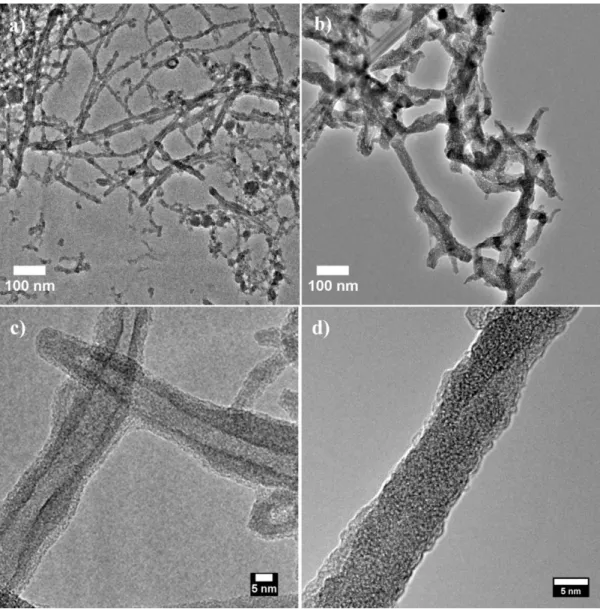
Figure 2.6. One-dimensional titania nanostructures after calcination. TEM images of peptide 1-templated titania a. nanotube network and c. nanotubes; TEM images of peptide 2-templated titania b. nanowire network and d. nanowire.
Exploiting soft nanofibrillar templates in nanofabrication processes enables synthesis of high-aspect-ratio materials with high surface area.83 Here, we obtained highly porous network of one-dimensional TiO2 nanostructures by using
peptide nanofiber templates (Figure 2.6). Due to the shape of the template-directed TiO2 growth, fast and directional charge transfer to the conductive
39
transparent oxide layer (anode) should be possible. This charge transfer enhancement should substantially decrease conduction losses, due to recombination process in the electrode. Moreover, nanostructured titania with high surface area provides increased interaction between TiO2 and the dye in
DSSC devices. To understand the effect of nanostructured TiO2 on DSSC
photovoltaic performance, three sets of solar cells were built from three different TiO2 materials (peptide 1-templated TiO2, peptide 2-templated TiO2 and
template-free TiO2). Peptide 1 leads to nanotubular TiO2 structures, while peptide
2 favors TiO2 nanowire architecture (Figures 2.6 a and b). As mentioned above,
the lysine residues have longer side chains compared to glutamate residues. This small difference affects final diameter of the nanofibers. Thicker peptide 1 nanofibers prevent complete sintering of the material into nanowire during the calcination process, therefore nanotubes are observed. The thickness of the self-assembled peptide nanofibers affects the resultant architecture of one-dimensional TiO2 nanostructures (Figure 2.6). It is crucial to obtain one-dimensional TiO2 in
its anatase phase – a semiconductor phase used for DSSC construction. The mineralized titania nanostructures were annealed at 450 °C to obtain anatase phase. The XRD pattern of the anatase phase obtained during sintering and annealing process is shown in Figures 2.7. The organic peptide template was removed during the calcination stage. It was previously demonstrated that the thermal decomposition of peptide completes at 350 °C.47
Thus, 450 °C is sufficient for both thermal decomposition of the organic peptide template and phase transformation of titania.
40
Figure 2.7. XRD spectra of template-free TiO2 (black), peptide 1-templated TiO2
(blue), peptide 2-templated TiO2 (red) powders.
Calcination process takes place directly on FTO glass, which minimizes the solar cell assembly steps. Stained with sensitizer (N719), peptide-templated materials were probed in dye sensitized solar cell experiments. In fully functional solar cell devices, nanostructured titania was sandwiched between two electrodes with addition of liquid I2/I- electrolyte. The amount of TiO2 on the FTO surface is an
important parameter, which affects the overall efficiency of the DSSC. Accurate measurement of the TiO2 amount was achieved by inductively coupled plasma –
mass spectrometry (ICP-MS). The amount of template-free synthesized TiO2 was
41
nanotubes synthesized by peptide nanofiber templates. It could be due to the three-dimensional structure of bulk TiO2 nanowires and nanotubes, which inhibit
the sintering and aggregation of titania during the calcination process. On the other hand, since template-free titania particles have no particular shape and size, they re-assemble on the surface during the calcination to form denser aggregations. Thus, after the calcination, the amount of adhered TiO2 on the
surface was higher for template-free synthesized nanoparticles.
The specific surface area of the TiO2 nanostructures were analyzed by using
nitrogen gas adsorption method, which relies on Brunauer-Emmett-Teller (BET) theory.89 The measurements showed that the surface area of peptide 1-templated nanotube network was more than five times and area of peptide 2-templated nanowire network was more than three times greater than that of template-free synthesized TiO2 particles (Table 2.1) The pore size of the TiO2 in DSSC should
be large enough to allow easy diffusion of electrolyte, while avoiding the recombination of redox species in the electrolyte.66 Therefore, one-dimensional nanostructures offer the best morphology. Since N719 dye molecules are not likely to aggregate, it could be assumed that dye should be adsorbed as monolayer;90,91 therefore, increasing the surface area causes increase in the amount of adsorbed dye and as a result, enhance the efficiency of the solar cell.92 The amount of adsorbed dye is expected to be greater for nanotubes and nanowires compared to template-free synthesized TiO2. Indeed, the average
amount of adsorbed dye was found to be 3 times greater for nanotubes and 1.5 times greater for nanowires compared to template-free particles, which does not contradict the surface area measurements (Table 2.1). Nevertheless, increase in
42
the dye loading observed for template synthesized materials is smaller than increase in the surface area. This incomplete dye loading can be rationalized by imperfect diffusion of the dye into porous structures.
Figure 2.8. Representative J–V spectra of devices based on peptide 1 (Pep-1), peptide 2 (Pep-2) templated and template-free TiO2 materials.
Photoconversion efficiencies of DSSCs were analyzed by a solar simulator set -up. The J-V characteristics of the photovoltaic devices are shown in Figure 2.8. The devices with nanostructured materials exhibited significantly greater photovoltaic performance. The cells produced on peptide 1 templated TiO2 nanotube
43
peptide 2 templated TiO2 nanowire electrodes and template-free TiO2 electrodes.
This is attributed to dramatic increase in the surface area of the electrode. Although fill factor values were comparable, open circuit voltage values for templated materials were around 760 mV, while template-free synthesized material did not exceed 620 mV (Table 2.1). Observed Voc enhancement is
attributed to bandgap widening caused by physical confinement of electro ns in nanostructured materials. Diffuse reflectance spectra indicate blue-shifted bandgap edges for templated materials (Figure 2.9). This clearly demonstrates important role of the peptide-templated materials in enhancing overall efficiency of the device performance.