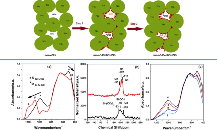
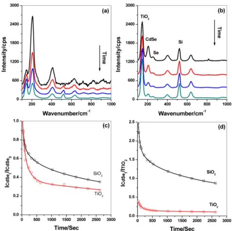
Modifying titania using the molten-salt-assisted self-assembly process for cadmium selenide-quantum dot-sensitized photoanodes
Tam metin
Şekil


Benzer Belgeler
This uncertainty on the part of EU’s future Cyprus policy as well as a growing future resentment on the part of Turkish Cypriots and Turkey may act as important challenges to the
She focuses in particu- lar on Hopkins’s lyric speaker’s “power to exploit language, and use it arbitrarily” to control the hearer (“The Negotiation of Power Relations in
Çalışmanın amacı, X, Y ve Z kuşaklarının kariyer algılarını, dört mevsim metaforu çerçevesinde ölçmeye çalışmak olduğundan, üç kuşakta bulunan
Cikan sonuplar uyannca, genel olarak gu s6ylenebilir: Eger genlik bilgisi bi- linen kesir dgerleri arasindaki fark l'e yakm ise, ki tam 1 oldugunda
The algorithm has two main components: (1) the solution of the smooth problem, i.e., minimization of G-y for a given value of 'Y, and (2) the reduction of 'Y and the
In this subsection, we demonstrate the performance of our proposed boosted regression algorithm on various real-life data sets, i.e., Kinematics and Alcoa Corporation Stock Price
Conclusion In obese adolescents, disordered eating attitudes and behaviors could be associated with anxiety and depressive symptoms.. Thus, all adolescents with obesity should
Tablo 1’de yer alan analiz sonuçlarına göre araştırmaya katılan çalışanların duygusal tükenmişlik ile duyarsızlaşma düzeylerinin düşük düzeyde olduğu, kişisel
