Direct application of the Complementary Functions
Method (CFM) to the static analysis of rotating disks
with both parabolic-varying thickness profile and
functionally graded (FG) material
Cem Boğa, Vebil Yıldırım
Online Publication Date: 1 May 2016
URL:
http://www.jresm.org/archive/resm2015.36me0129.html
DOI:
http://dx.doi.org/10.17515/resm2015.36me0129
Journal Abbreviation:
Res. Eng. Struct. Mat.
To cite this article
Boga C, Yildirim V. Direct application of the Complementary Functions Method (CFM) to the
static analysis of rotating disks with both parabolic-varying thickness profile and functionally
graded (FG) material. Res. Eng. Struct. Mat., 2017; 3(1): 11-25.
Disclaimer
All the opinions and statements expressed in the papers are on the responsibility of author(s) and are not to be regarded as those of the journal of Research on Engineering Structures and Materials (RESM) organization or related parties. The publishers make no warranty, explicit or implied, or make any representation with respect to the contents of any article will be complete or accurate or up to date. The accuracy of any instructions, equations, or other information should be independently verified. The publisher and related parties shall not be liable for any loss, actions, claims, proceedings, demand or costs or damages whatsoever or howsoever caused arising directly or indirectly in connection with use of the information given in the journal or related means.
*Corresponding author: [email protected]
DOI: http://dx.doi.org/10.17515/resm2016.36me0129
Res. Eng. Struct. Mat. Vol. 3 Iss. 1 (2017) 11-25 11
Research Article
Direct application of the Complementary Functions Method (CFM)
to the static analysis of rotating disks with both parabolic-varying
thickness profile and functionally graded (FG) material
Cem Boğa*1, Vebil Yıldırım2
1 Vocational School of Adana, Çukurova University, Adana, Turkey
2 Department of Mechanical Engineering, Çukurova University, Adana, Turkey Article Info Abstract
Article history: Received 10 Feb 2016 Revised 25 Apr 2016 Accepted 30 Apr 2016
In this study elastic stresses and displacements of a rotating variable-thickness disk made of a radially functionally graded (FG) material are calculated numerically in an accurate manner based on the Complementary Functions Method (CFM). The general parabolic function which determines the variation of the thickness of the disk includes concave, convex and linear disk profiles. It is assumed that the inner surface is to be all-metal and the outer surface is to be all-ceramic. Young’s modulus and density vary between inner and outer surface by obeying the volume-fraction material grading rule. The disk is fixed to a shaft at the inner surface and free expansion exists at the outer surface. For the Ti-6Al-4V − Si3N4 metal-ceramic pair, the effect of the inhomogeneity constants on the
stress and displacement is investigated. Results are presented in both tabular and graphical forms. Those presented in tables may form benchmark data for purely numerical calculations.
© 2016 MIM Research Group. All rights reserved. Keywords:
Complementary Functions Method, Functionally graded material, Rotating disk, Variable thickness, Elastic analysis
1. Introduction
There are numerous papers on the stationary/rotating disks on the available literature. The research on stress analyses of anisotropic rotating disks were initiated at the beginning of 1970 [1, 2]. Analytical [3-10] and numerical [11-18] studies for stress/strain analyses of rotating disks made of functionally graded (FG) materials, which comes from advanced composites, have been considerably increased since 1990.
You et al. [4] proposed a closed form solution of rotating circular disks made of FG materials subjected to constant angular velocity and to uniform temperature change by considering Young’s modulus, thermal expansion coefficient and density to be the functions of the radial coordinate. They obtained the governing differential equation in terms of the radial stress. You et al. [5] also developed similar analytical solution technique to determine deformations and stresses in circular disks made of FG materials subjected to internal and/or external pressure. They have taken material properties to be linear variations, and transformed the governing equation into a hyper-geometric equation. Durodola and Attia [11,12] studied elastic analysis of disks made of FG orthotropic materials by means of finite element analysis using commercial software. They modeled the disk as a non-homogeneous orthotropic material such as the one obtained through non-uniform reinforcement of metal matrix by long fibers and considered three types of gradation distribution of the Young’s modulus, in the hoop direction relative to matrix material modulus. Chen et al. [13] performed analytically 3-D static analysis of disks made of transversely isotropic FG materials. Lubarda [14] handled a numerical analysis based on the finite difference technique for the disks subjected to inner/outer pressures. Peng
12
and Li [15-16] investigated polar orthotropic FG rotating disks [15], a sandwich solid disk rotating about its center axis at constant angular velocity [16] by using Fredholm integral solutions. Tütüncü and Temel [17] used the complementary functions method to work axisymmetric displacements and stresses of a cylinder/sphere/disk subjected to only an inner pressure. Eraslan and Arslan [18] obtained analytical and numerical solutions to rotating uniform FG solid and annular disks.
In all the above mentioned studies, the analyses were performed for uniform disks with constant thickness [1-18].
There are only a few studies performed for homogeneous disks with variable thickness in the literature [19-23]. Apatay and Eraslan [19] proposed a thickness profile in parabolic form containing two geometric parameters for rotating disks and presented analytical solutions in terms of hypergeometric functions for rotating both solid and annular disks. In the case of annular disks, they treated free, radially constrained and pressurized boundary conditions. They showed that the stresses in parabolic disks were lower in magnitude than those in uniform thickness disks under the same conditions. They also investigated the effect of various parameters on the elastic limit angular velocities using the Von-Mises yield criterion. The calculated elastic limit angular velocities were found to be affected significantly by the reduction in the edge thickness of the disk. Argeso [20] obtained analytical solutions of two different annular rotating disk problems and numerically verified the closed form solutions by the nonlinear shooting method. The first problem involved a variable profile rotating disk having constant valued material properties, whereas in the second problem a constant profile FGM rotating disk was considered.
Unfortunately studies for FG disks with variable thickness are limited. From those by using simple power material grading rule, Bayat et. al. [24] presented analytical elastic solutions for uniform rotating disks and semi-analytical elastic expressions for rotating disks with parabolic/hyperbolic sections. These semi-analytic solutions were obtained by dividing the disk having continuously-variable sections into sub-disk modulus with constant thickness. Bayat et. al. [25], in another study, used an exponential and Mori-Tanaka material grading rules for variable-sectioned disks under fixed-free boundary conditions. In this study again governing equation with variable coefficients was changed into a system of ordinary differential equations with constant coefficients with a number of virtual sub-domains. They considered two kinds of FG materials namely metal-ceramic and ceramic-metal. The results showed that the radial displacement in ceramic-metal FG disks are smaller than those in metal-ceramic FG disks, and that a rotating FG disk with concave thickness profile can be more efficient than the one with uniform thickness. Recently Boğa and Yıldırım [26] presented an exact numerical solution to the FG rotating disk with a parabolic thickness profile and Mori-Tanaka grading scheme with the help of the CFM. They verified their results with the analytical results for the uniform disk with simple power-law grading rule. They also studied the effect of many parameters such as angular velocity, metal-ceramic pairs, and material grading index on the stresses and displacements. In another work with CFM, Boğa and Yıldırım [27] handled elasto-static linear analysis of the rotating FG disks with a divergent/convergent hyperbolic and a uniform disc profiles. They considered three different ceramic-metal pairs and an exponential type of material grading patterns. Kacar and Yıldırım [28], by using the simple power material grading rule, solved analytically the elasticity equations of radially FG pressurized thick-walled rotating cylindrical and spherical vessels. They presented all the closed-form solutions of both the radial and hoop stresses, and the radial displacements in the simplest and most convenient form for scientists, designers, engineers, and the others.
13 In the present work, the continuously variable-sectioned disk problem-without using any additional assumptions except the infinitesimal plane-stress elasticity theory and a constant Poisson’s ratio assumption for FG material-is handled with the help of the complementary functions method [17, 26-27, 29-41] based on the direct solution of the differential equations with variable coefficients. By doing so, accomplishment of the exact numerical solutions to the real problem becomes possible. Similar to Fredholm integration technique, the method under consideration is a general method and independent from the function types chosen for both disk profile and material grading rule.
Since 1990’s, the second author used to this method, the complementary functions method (CFM), in the solution of more complex problems such as static/dynamic/buckling analyses of curvilinear planar/spatial/helical bars, static analysis of axisymmetric shells, and thermo-elastic dynamic analysis of infinite cylinders subjected to both inner and outer pressures [32-41]. From the nature of the differential equations derived, this method is again preferred as an effective and accurate solution technique in the present study.
2. Differential Equations
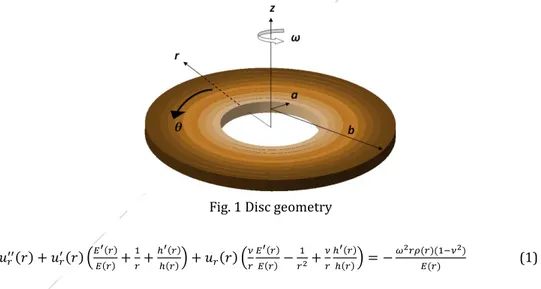
Under infinitesimal deformations, a state of plane stress and axisymmetric loading assumptions, and by using field equations (strain-displacement, equilibrium and stress-strain) the differential equation governing the elastostatic behavior of a FG disk with variable thickness (Fig. 1) is derived in a general compact form as follows [d( )/dr =( )′].
Fig. 1 Disc geometry 𝑢𝑟′′(𝑟) + 𝑢𝑟′(𝑟) (𝐸 ′(𝑟) 𝐸(𝑟) + 1 𝑟+ ℎ′(𝑟) ℎ(𝑟)) + 𝑢𝑟(𝑟) ( 𝜈 𝑟 𝐸′(𝑟) 𝐸(𝑟)− 1 𝑟2+ 𝜈 𝑟 ℎ′(𝑟) ℎ(𝑟)) = − 𝜔2𝑟𝜌(𝑟)(1−𝜈2) 𝐸(𝑟) (1)
Where r is the radial coordinate, 𝑢𝑟(𝑟) is the radial displacement, ν is the Poisoon’s ratio
which is assumed to be constant along the radial direction, ℎ(𝑟) is the disk profile function,
ω is the angular velocity, E(r) is a function which defines the variation of the Young’s
modulus along the radial direction, 𝜌(𝑟) is a function describes the variation of the material density in the radial coordinate.
Eq. (1) is a second-degree non-homogeneous differential equation with variable coefficients. If the material grading pattern is chosen as a simple power rule, or as a linear function of the radial coordinate, or as an exponential function and additionally if the disk thickness is assumed to be constant or varied hyperbolically, then a closed-form solution
14
may be attained [3-10, 28, 42]. For other cases it is evitable to resort to any numerical method for the solution process [19-27].
The complementary functions method (CFM) whose methodology is given in Appendix is an effective and accurate method which is used directly in the solution of the differential equations with variable coefficients [17, 26-27, 29-41]. To do this, CFM reduces a boundary-value problem (BVP) to an initial-value problem (IVP). In the solution process with CFM, first of all, Eq. (1) which is in the form of a second-degree differential equation is rewritten in the form of two first-degree differential equations by choosing appropriate variables to apply IVP as follows
𝑢𝑟′ = − 𝜈 𝑟 𝑢𝑟− 𝜈2−1 𝐸(𝑟) 𝜎𝑟 (2a) 𝜎𝑟′ = 𝐸(𝑟) 𝑟2 𝑢𝑟+ { 𝜈−1 𝑟 − ℎ′(𝑟) ℎ(𝑟)} 𝜎𝑟− 𝜔 2𝑟𝜌(𝑟) (2b)
Then this first-order equation being a mildly-stiff equation is numerically solved by either a fourth-order Runge-Kutta method (RK4) or some other explicit Runge-Kutta 4/5 methods such as Fehlber 4(5), Dormand-Prince 5(4), or Bogacki-Shampine 5(4) under given boundary conditions.
In this study the following real boundary conditions are used for a rotating disk attached a shaft at the inner surface. At the outer surface, the disk may freely expand. That is there is no radial stress at the outer surface.
𝑢𝑟(𝑎) = 0 ; 𝜎𝑟(𝑏) = 0 (3)
Although solution of Eq. (2) gives simultaneously both the radial displacement and radial stress, it is necessary to compute the hoop stress by using related elasticity equations namely stress-strain and strain-displacement relations or just Hook’s law in terms of displacements.
As is well known, a computer cannot differentiate but it can easily do a difference. That is while differentiation is a continuous process, differencing is a discrete process. Therefore, the differential equation is solved by replacing differentiation by differencing in numerical integral techniques. In general, implicit integration methods are more efficient for stiff equations, which usually feature a rapidly decaying solution, while explicit RK methods are appropriate for the equations are not stiff. Explicit RK methods, in which Bogacki-Shampine 5(4) offers the least expensive and the most accurate solution by evaluating more slopes with a greater number of step sizes, which are systematically defined, than implicit methods to accurately estimate the solution. However, this takes lots of time. So they do not render economical solutions. For this kind of medium-stiff problems, RK4 is more efficient and economical (see Table 1). Beyond RK4, as stated above, the explicit RK methods become relatively more expensive to compute.
It is important to mention that Eq. (1) may be written in the form of two first order differential equations by selecting simply 𝑢𝑟′ and 𝑢𝑟′′ as variables to be used in the solution
of an initial value problem (IVP) as in Reference [17] (see Appendix). However, in this case after obtaining solutions for 𝑢𝑟 and 𝑢𝑟′ with CFM both the radial and hoop stresses should
be computed from Hooke’s law in terms of displacements. If one utilizes Eqs. (2), both the volume and execution time of the computer code are considerably reduced. Therefore, variables 𝑢𝑟′ and 𝜎𝑟′ in Eqs. (2) are referred to as appropriate variables which require just
additional computation of the hoop stress. Briefly, determination of the proper variables in IVP strictly affects both the execution time and volume of the computer code.
15
3. Disk Profile and Material Grading Pattern
In the present study, the variation of the thickness in radial direction is determined by a parabolic function given below.
ℎ(𝑟) = ℎ0(1 − 𝑞 (𝑏𝑟) 𝑘
) (4) Where, ℎ0 is the thickness at the center of the disk, q is a constant, b is the radius of the disk
at the outer surface. Exponent k is another constant having positive numerical values. Eq. (4) gives a convex disk profile for k-values greater than unit (k>1), and a concave disk profile for 0<k<1. If k-value is unit then the radial variation of the thickness becomes linear. For material grading pattern, volume fraction rule is used. By assuming the inner surface is to be all-Material/a and the outer surface is to be all-Material/b, the following functions for the variation of both Young’s modulus and material density from the inner surface to the outer surface are derived.
𝐸(𝑟) = (𝐸𝑏− 𝐸𝑎) ( 𝑟−𝑎 𝑏−𝑎) 𝑛 + 𝐸𝑎 (5a) 𝜌(𝑟) = (𝜌𝑏− 𝜌𝑎) (𝑏−𝑎𝑟−𝑎) 𝑛 + 𝜌𝑎 (5b)
Where n is called as an inhomogeneity index/constant/exponent/parameter. As stated above in the present study the Poisson’s ratio is assumed to be constant along the radial direction. In the numerical results, to get more realistic solutions, an arithmetical mean of these quantities is used as follows.
𝝂 =𝝂𝒂+𝝂𝒃
𝟐 (6)
In the present study Material/a is chosen as metal and Material/b is chosen as ceramic at the inner and outer surfaces, respectively.
4. Verification of CFM results with the analytical solutions
Using the linear plane elasticity equations, Kacar et. al. [42] derived exact expressions in most possible concise form for all kind of axisymmetric rotating hollow structures made of an isotropic and homogeneous material to present a compact source for students, engineers, academics and other users. In this study [42] both the inner and outer pressures are taken into account at the same time together with the constant angular velocity. For the boundary conditions considered in the present study, the following formulas are presented by Kacar et. al. [42] for uniform disks.
) 1 ( ) 1 ( 8 ) 3 ( ) 1 ( ) 1 ( ) 1 ( ) 1 )( ( 2 2 2 2 2 2 2 2 2 2 2 2 b a r E b r b a r b r a ur
) 1 ( ) 1 ( 8 )) 3 )( 1 ( ) 3 )( 1 )( ( ) 1 ( )( ( 2 2 2 2 2 2 2 2 2 2 4 2 2 b a r r b a r b a r b r(7)
( 1) ( 1)
8 )) 1 3 ( ) 3 ( )( 1 ( )) 1 3 ( ) 3 )(( 1 ( ) 1 )( ( 2 2 2 2 2 2 2 2 2 4 4 4 2 2 2 b a r r b r b a r b a r b16
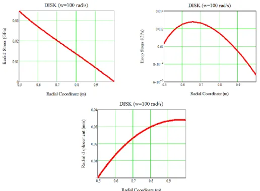
𝜌 = 7800 𝑚𝑘𝑔3; 𝐸 = 200 GPa Eq. (7) are calculated numerically and results are illustrated in Fig. 2 to get an idea for the static response of a uniform disk rotating at a constant angular velocity and made of an isotropic homogeneous material. As seen from this figure that the maximum radial stress occurs at the inner surface of the disk while the maximum hoop stress is between the inner and mid-plane surfaces. If just rotation effect is considered, radial stresses become more significant.
Fig. 2 The static response of a uniform isotropic rotating disk
Table 1 Comparison of analytical and CFM results for a uniform disk made of an isotropic and homogeneous material at 𝜔 = 100 rad/s
𝒖𝒓 (𝑚) 𝝈𝒓(𝑃𝑎) 𝝈𝜽(𝑃𝑎)
r Analytical CFM Analytical CFM Analytical CFM
0.5 0.6 0.7 0.8 0.9 1 0.000000E+00 1.347617E-05 2.322490E-05 2.977889E-05 3.331582E-05 3.383581E-05 0.000000E+00 1.347617E-05 2.322489E-05 2.977889E-05 3.331581E-05 3.383580E-05 3.445551E+07 2.671008E+07 1.999114E+07 1.351880E+07 6.920497E+06 0.000000E+00 3.445551E+07 2.671008E+07 1.999114E+07 1.351880E+07 6.920497E+06 0.000000E+00 1.033665E+07 1.250508E+07 1.263303E+07 1.150036E+07 9.479664E+06 6.767161E+06 1.033665E+07 1.250508E+07 1.263302E+07 1.150036E+07 9.479663E+06 6.767160E+06
Comparison of the analytical and CFM results for a uniform disk made of an isotropic and homogeneous material at 𝜔 = 100 rad/s is also presented in Table 1. As seen from Table 1, an excellent harmony between the results is observed. From the table it is also revealed that Runge Kutta 4 offers an accurate and economical solutions for this kind of problems.
17 Table 2 Isotropic material properties considered in the present study
Material E (GPa) ρ (kg/m3) ν
Metal (Ti-6Al-4V) 122.557 2370 0.29
Ceramic (Silicon Nitride-Si3N4) 348.43 4429 0.24
5. Numerical Examples
In the present study a real problem is studied instead of a hypothetical problem which does not coincide with a physical material and with real disk dimensions.
a) Parabolic-convex profile
b) Parabolic-concave profile
c)
Linear profileFig. 3 Disc profiles considered in this study
Geometrical properties of the disk considered in the numerical analysis are chosen as follows to obey the plane-stress assumption (Fig. 3): 𝑎 =0.02 m, 𝑏 = 0.2 m , 𝑞 = 0.6 , ℎ𝑜=
0.02 m, 𝑘 = 2 (for a convex disk profile), 𝑘 = 0.5 (for a concave disk profile), 𝑘 = 1 (for a linear disk profile). To study the effect of the angular velocity on the elastic stress and displacements, the following constant values are used in computations for linear analysis: ω=100 rad/s and ω=150 rad/s
In the present study an isotropic metal is taken as Ti-6Al-4V and an isotropic ceramic is chosen as Si3N4. Then they are combined according to the Eqs. (5) to get a FG material for
two different inhomogeneity indices (n=0.5 and n=2).
Material properties are given in Table 2. Fig. 4 shows the variation of the FG material properties along the radial direction of the disk according to the material grading pattern defined in Eq. (5) to form benchmark data for numerical calculations.
After determining the necessary numerical data, the problem is solved numerically with the help of a computer program devised by the authors in a Fortran-code. In the present study RK4, being the most popular RK method, is used in the solution of differential equation set with the help of the IVP since it offers a good balance between order of accuracy and cost of computation (See Table 1). Numerical results for the radial
18
displacement, radial and hoop stresses are presented in tabular (Table 3) and in graphical forms (Figs. 5-7).
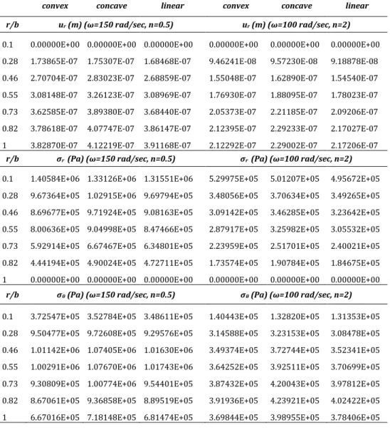
Table 3 Numerical results for both n=0.5 and n=2 at different angular velocities
convex concave linear convex concave linear r/b ur (m) (ω=150 rad/sec, n=0.5) ur (m) (ω=100 rad/sec, n=2)
0.1 0.00000E+00 0.00000E+00 0.00000E+00 0.00000E+00 0.00000E+00 0.00000E+00 0.28 1.73865E-07 1.75307E-07 1.68468E-07 9.46241E-08 9.57230E-08 9.18878E-08 0.46 2.70704E-07 2.83023E-07 2.68859E-07 1.55048E-07 1.62890E-07 1.54540E-07 0.55 3.08148E-07 3.26123E-07 3.08969E-07 1.76930E-07 1.88095E-07 1.78023E-07 0.73 3.62585E-07 3.89380E-07 3.68440E-07 2.05373E-07 2.21185E-07 2.09206E-07 0.82 3.78618E-07 4.07747E-07 3.86147E-07 2.12395E-07 2.29233E-07 2.17027E-07 1 3.82870E-07 4.12219E-07 3.91168E-07 2.12292E-07 2.29002E-07 2.17206E-07
r/b σr (Pa) (ω=150 rad/sec, n=0.5) σr (Pa) (ω=100 rad/sec, n=2)
0.1 1.40584E+06 1.33126E+06 1.31551E+06 5.29975E+05 5.01207E+05 4.95672E+05 0.28 9.67364E+05 1.02915E+06 9.69794E+05 3.48056E+05 3.70634E+05 3.49265E+05 0.46 8.69677E+05 9.71924E+05 9.08163E+05 3.09142E+05 3.46285E+05 3.23642E+05 0.55 8.00636E+05 9.04998E+05 8.47466E+05 2.87917E+05 3.25982E+05 3.05532E+05 0.73 5.92914E+05 6.67467E+05 6.34801E+05 2.23959E+05 2.51701E+05 2.40021E+05 0.82 4.44194E+05 4.90024E+05 4.72711E+05 1.73574E+05 1.90784E+05 1.84675E+05 1 0.00000E+00 0.00000E+00 0.00000E+00 0.00000E+00 0.00000E+00 0.00000E+00
r/b σθ (Pa) (ω=150 rad/sec, n=0.5) σθ (Pa) (ω=100 rad/sec, n=2)
0.1 3.72547E+05 3.52784E+05 3.48611E+05 1.40443E+05 1.32820E+05 1.31353E+05 0.28 9.50477E+05 9.72608E+05 9.29576E+05 3.14588E+05 3.23153E+05 3.08478E+05 0.46 1.01142E+06 1.07405E+06 1.01630E+06 3.49374E+05 3.72744E+05 3.52341E+05 0.55 1.00291E+06 1.07670E+06 1.01743E+06 3.64252E+05 3.92511E+05 3.70699E+05 0.73 9.30809E+05 1.00774E+06 9.54401E+05 3.87432E+05 4.20043E+05 3.97812E+05 0.82 8.67061E+05 9.36858E+05 8.89519E+05 3.91936E+05 4.23921E+05 4.02422E+05 1 6.67016E+05 7.18148E+05 6.81474E+05 3.69844E+05 3.98955E+05 3.78406E+05
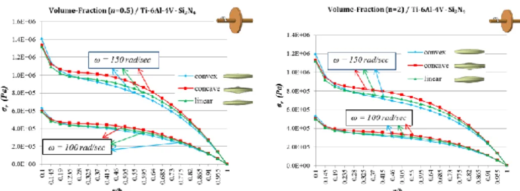
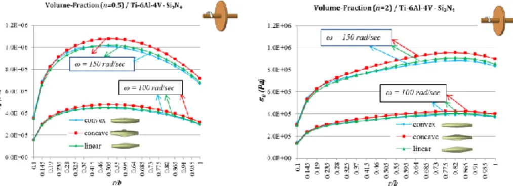
Fig. 5 presents that the radial displacement increases with increasing angular velocity and inhomogeneity index towards the outer surface of the disc. The behaviors of convex and linear disk profiles are very close to each other. Concave disk profile offers greater radial displacement than the others. It is observed from Fig. 6 that maximum radial stress is at the inner surface of the disk in all the cases as in homogeneous materials. Increasing inhomogeneity index results in a decrease in the radial stress. The radial stress increases with increasing angular velocity. The behaviors of convex and linear disk profiles are again close to each other. Concave disk profile offers greater radial stresses than the other disk profile. Fig. 7 illustrates the location of the maximum hoop stress is shifted from the mid-surface to the outer mid-surface with increasing inhomogeneity constant. Increasing inhomogeneity constants offers smaller hoop stresses. The hoop stress also increases with
19 increasing angular velocity. The behaviors of convex and linear disk profiles are again very close to each other and concave disk profile presents higher radial stresses.
Fig. 4 Radially variation of the FG material properties according to Eq. (5) (n=0.5 and
n=2)
Fig. 5 Variations of the radial displacement with respect to the angular velocity and disk profiles for two different inhomogeneity indexes
Fig. 6 Variations of the radial stresses with respect to the angular velocity and disk profiles for two different inhomogeneity indexes
20
Fig. 7 Variations of the hoop stresses with respect to the angular velocity and disk profiles for two different inhomogeneity indexes
6. Conclusions
It is well known that there is no any specific result which is valid for all FG material types. However generally speaking, FGM results are mainly different from isotropic-material results according to the material grading pattern together with the type of metal-ceramic pair, type of the disk profile and boundary conditions. For any combinations of those parameters for a FG disk, it is necessary to solve differential equations to have a consistent idea. In this respect, CFM will be an excellent device to get accurate results in a short time. In addition, the method proposed in the present study may also be used for other types of analyses such as thermal, thermoelastic, dynamic etc. of this type structures.
The general conclusions of the present study may be reached as:
The maximum radial stress is at the inner surface of the FG disk similar to a disk made of an isotropic and homogeneous material for the boundary condition considered (see Fig. 2 and 6).
While the maximum hoop stress is closer to the inner surface for homogeneous disk, it shifts through the outer surface for inhomogeneous ones.
The elastic stresses become lower when the inhomogeneity constant increases. However, the radial displacement increases with increasing inhomogeneity parameter.
Maximum radial displacement is located at the outer surface of the disk.
Concave disk profile has higher radial displacement values while convex one presents lesser displacements.
Concave disk profile also shows the highest radial and hoop stresses.
The numerical values of the elastic responses increase with increasing angular velocity.Acknowledgement
The authors acknowledge and appreciate the financial support from the Council of Scientific Research Projects (BAP) at the Çukurova University under Project Contracts No: MMF-2013-D12.
21
Appendix
Let’s consider the following second-degree differential equation as an example 𝑦′′(𝑥) + 1
𝑥2𝑦(𝑥) = 𝑥 (a)
with boundary conditions, 𝑦(1) + 𝑦′(1) = 0 and y(2)0, to explain the general
methodology of CFM. Here solution interval will be [a, b] = [1, 2]. Physical boundary conditions may be written as follows
at x=a=1 → 𝑦(𝑥) + 𝑦′(𝑥) = 0 (b) at x=b=2 → y(x)0 or 𝑦(𝑎) + 𝑦′(𝑎) = 0 (c) 𝑦(𝑏) = 0 or 𝑦(1) + 𝑦′(1) = 0 (d) 𝑦(2) = 0
In CFM, general solution of Eq. (a) is given by
𝑦(𝑥) = 𝑦0(𝑥) + 𝑏1𝑦1(𝑥) + 𝑏2𝑦2(𝑥) (e)
All terms at the right side should be determined by the method. After converting Eq. (a) into IVP, this is done in four solution stages. The prescribed boundary conditions are first used to find 𝑦0(𝑥), 𝑦1(𝑥) and 𝑦2(𝑥) in Eq. (e) in the first three stages. At the final stage, the
physical boundary conditions are used to determine 𝑏1 and 𝑏2.
Let’s begin by converting BVP in Eq. (a) to IVP with the same solution interval [a,b] = [1,2] by simply letting 𝑧1= y(𝑥) (f) 𝑧2= 𝑦′(𝑥) as follows 𝑧1′ = 𝑧2 (g) 𝑧2′ = − 1 𝑥2𝑧1+ 𝑥 or x z z x dx dz dx dz 0 0 1 1 0 2 1 2 2 1 (h) Now, physical boundary conditions may be rewritten in terms of new variables as
0 ) 1 ( ) 1 ( 2 1 z z → z1(a)z2(a)0 (i) 0 ) 2 ( 1 z → z1(b)0
22
In the first stage, homogeneous solution of Eq. (g) or Eq. (h) with prescribed initial conditions,z1(1)0, z2(1)0{y0(a)0, 𝑦0′(𝑎) = 0}, gives
{𝑧𝑧1= 𝑦0
2= 𝑦0′} (j)
In the second stage, again, homogeneous solution of the same equation with prescribed initial conditions, z1(1)1, z2(1)0{y1(a)1, 𝑦1′(𝑎) = 0}, yields
{𝑧𝑧1= 𝑦1
2= 𝑦1′} (k)
In the third stage, homogeneous solution of the same equation with prescribed initial conditions, z1(1)0, z2(1)1{y2(a)0, 𝑦2′(𝑎) = 1}, offers
{𝑧𝑧1= 𝑦2
2= 𝑦2′} (l)
After substituting 𝑦0(𝑥), 𝑦1(𝑥) and 𝑦2(𝑥) into the general solution, Eq. (e), the physical
boundary conditions of the differential equations, now, are applied to determine the unknown coefficients 𝑏1 and 𝑏2 in a straight forward manner.
To apply the physical boundary conditions given 𝑏𝑦 (𝑦(1) + 𝑦′(1) = 0, 𝑦(2) = 0), the
first derivative of the general solution, Eq. (e), is required. If those coefficients are constant, then the first derivative will be in the form of
𝑦′(𝑥) = 𝑦
0′(𝑥) + 𝑏1𝑦1′(𝑥) + 𝑏2𝑦2′(𝑥) (m)
Physical boundary conditions are written in the following form 𝑦(1) = 𝑦0(1) + 𝑏1𝑦1(1) + 𝑏2𝑦2(1) 𝑦′(1) = 𝑦 0′(1) + 𝑏1𝑦1′(1) + 𝑏2𝑦2′(1) (n) 𝑦(2) = 𝑦0(2) + 𝑏1𝑦1(2) + 𝑏2𝑦2(2) For 𝑦(1) + 𝑦′(1) = 0 we have [𝑦0(1) + 𝑦0′(1)] + 𝑏1[𝑦1(1) + 𝑦1′(1)] + 𝑏2[𝑦2(1) + 𝑦2′(1)] = 0 (o) fory(2)0 we reach 𝑦0′(2) + 𝑏1𝑦1′(2) + 𝑏2𝑦2′(2) = 0 (p)
Application of the real boundary conditions, the following equation set is attained by combining Eqs. (o) and (p).
) 2 ( ' ) 1 ( ' ) 1 ( ) 2 ( ) 2 ( ) 1 ( ' ) 1 ( ) 1 ( ' ) 1 ( 0 0 0 2 1 2 1 2 2 1 1 y y y b b y y y y y y (r)
It may be written in a compact form as follows
A B = C (s) Here A is the coefficient matrix, C is the load vector. Solution of this equation gives the numerical values of the elements of unknown vector, B.
The solution process is terminated by substitution of the elements of vector B in the general solution, Eq. (e).
It may be noted that in this solution IVP technique z1y(r)and z2y'(r) are simultaneously obtained in each step determined above.
23
References
[1] Murthy D, Sherbourne A. Elastic stresses in anisotropic disks of variable thickness. International Journal of Mechanical Sciences
,
1970; 12(7):627-640. Doi:10.1016/0020-7403(70)90093-7[2] Reddy TY, Srinath H. Elastic stresses in a rotating anisotropic annular disk of variable thickness and variable density. International Journal of Mechanical Sciences, 1974; 16(2):85-89. Doi:10.1016/0020-7403(74)90078-2
[3] Horgan C, Chan A. The stress response of functionally graded isotropic linearly elastic rotating disks. Journal of Elasticity, 1999; 55(3):219-230. 10.1023/A:1007644331856 [4] You LH, You XY, Zhang JJ, Li J. On rotating circular disks with varying material properties. Zeitschrift für angewandte Mathematik und Physik, 2007; 58(6): 1068-1084. [5] You LH, Wang JX, Tang BP. Deformations and stresses in annular disks made of functionally graded materials subjected to internal and/or external pressure. Meccanica, 2009; 44:283–292. DOI 10.1007/s11012-008-9174-y
[6] Çallioğlu H, Bektaş NB, Sayer M. Stress analysis of functionally graded rotating discs: analytical and numerical solutions. Acta Mechanica Sinica, 2011; 27(6):950-955. Doi:10.1007/s10409-011-0499-8
[7] Zenkour AM. Analytical solutions for rotating exponentially-graded annular disks with various boundary conditions. International Journal of Structural Stability and Dynamics, 2005; 5(04):557-577. Doi:10.1142/S0219455405001726
[8] Zenkour A. Elastic deformation of the rotating functionally graded annular disk with rigid casing. Journal of Materials Science, 2007; 42(23):9717-9724. Doi:10.1007/s10853-007-1946-6
[9] Zenkour A. Stress distribution in rotating composite structures of functionally graded solid disks. Journal of Materials Processing Technology, 2009; 209(7):3511-3517. Doi:10.1016/j.jmatprotec.2008.08.008
[10] Nejad MZ, Abedi M, Lotfian MH, Ghannad M. Elastic analysis of exponential FGM disks subjected to internal and external pressure. Central European Journal of Engineering, 2013; 3(3):459-465. Doi:10.2478/s13531-013-0110-0
[11] Durodola J, Attia O. Deformation and stresses in functionally graded rotating disks. Composites Science and Technology, 2000; 60(7):987-995. Doi:10.1016/S0266-3538(99)00197-9.
[12] Durodola JF, Attia O. Property gradation for modification of response of rotating MMC disks. Material Sciences Technology, 2000;16:919-924.
[13] Chen J, Ding H, Chen W. Three-dimensional analytical solution for a rotating disc of functionally graded materials with transverse isotropy. Archive of Applied Mechanics, 2007; 77(4):241-251. Doi:10.1007/s00419-006-0098-5
[14] Lubarda VA. On pressurized curvilinearly orthotropic circular disk, cylinder and sphere made of radially nonuniform material. Journal of Elasticity, 2012; 109(2):103-133. Doi:10.1007/s10659-012-9372-7
24
[15] Peng X-L, Li X-F. Elastic analysis of rotating functionally graded polar orthotropic disks. International Journal of Mechanical Sciences, 2012; 60(1):84-91. Doi:10.1016/j.ijmecsci.2012.04.014
[16] Peng XL, Li XF. Effects of gradient on stress distribution in rotating functionally graded solid disks. Journal of Mechanical Science and Technology, 2012; 26(5):1483-1492. [17] Tutuncu N, Temel B. A novel approach to stress analysis of pressurized FGM cylinders, disks and spheres. Composite Structures, 2009; 91(3):385-390. Doi:10.1016/j.compstruct.2009.06.009
[18] Eraslan AN, Arslan E. Analytical and numerical solutions to a rotating FGM disk. Journal of Multidisciplinary Engineering Science and Technology, 2015; 2(10): 2843-2850. [19] Apatay T, Eraslan AN. Elastic deformation of rotating parabolic discs: Analytical solutions (in Turkish). Journal of the Faculty of Engineering and Architecture of Gazi University, 2003; 18(2):115-135.
[20] Argeso H. Analytical solutions to variable thickness and variable material property rotating disks for a new three-parameter variation function. Mechanics Based Design of Structures and Machines, 2012; 40:133-152.
[21] You L, Tang Y, Zhang J, Zheng C. Numerical analysis of elastic–plastic rotating disks with arbitrary variable thickness and density. International Journal of Solids and Structures, 2000; 37(52):7809-7820. Doi:10.1016/S0020-7683(99)00308-X
[22] Eraslan AN, Akgül F. Yielding and elastoplastic deformation of annular disks of a parabolic section subject to external compression. Turkish Journal of Engineering and Environmental Sciences, 2005; 29(1):51-60.
[23] Zenkour AM, Mashat DS. Analytical and numerical solutions for a rotating annular disk of variable thickness. Applied Mathematics, 2010; 1(5):431-438. Doi:10.4236/am.2010.15057
[24] Bayat M, Saleem M, Sahari B, Hamouda A, Mahdi E. Analysis of functionally graded rotating disks with variable thickness. Mechanics Research Communications, 2008; 35(5):283-309. Doi:10.1016/j.mechrescom.2008.02.007
[25] Bayat M, Sahari B, Saleem M, Dezvareh E, Mohazzab A. Analysis of functionally graded rotating disks with parabolic concave thickness applying an exponential function and the Mori-Tanaka scheme. IOP Conference Series: Materials Science and Engineering, 2011: IOP Publishing. Doi:10.1088/1757-899X/17/1/012005
[26] Boğa C, Yıldırım V. Application of the complementary functions method to an accurate elasticity solution for the radially functionally graded (FG) rotating disks with continuously variable thickness and density, 11th International Conference, Mechatronic Systems and Materials (MSM 2015), pp. 37-38, Kaunas, Lithuania, July, 2015.
[27] Boğa C, Yıldırım V. Linear elastostatic analysis of functionally graded (FG) rotating disks with hyperbolic thickness variation, TUMTMK XIX. National Mechanics Congress, Karadeniz Technical University, Trabzon, Turkey, August, 2015.
[28] Kacar İ. and Yıldırım V. Analytical solution of the elasticity equations of pressurized rotating cylindrical and spherical vessels made of functionally graded materials, TUMTMK XIX. National Mechanics Congress, Karadeniz Technical University, Trabzon, Turkey, August, 2015.
[29] Aktas Z. Numerical solutions of two-point boundary value problems. Ankara, Turkey: METU, Dept of Computer Eng, 1972.
25 [30] Roberts S, Shipman J. Fundamental matrix and two-point boundary-value problems. Journal of Optimization Theory and Applications, 1979; 28(1):77-88. Doi: 10.1007/BF00933601
[31] Mengi Y. Lecture notes of numerical analysis. University of Çukurova, Department of Civil Engineering, Adana, Turkey, 1985.
[32] Haktanir V, Kıral E. Direct application of complementary functions method to axisymmetrical shells and cylindrical vaults (barrels). Journal of Isparta Engineering Faculty of Akdeniz University, 1991; 6:220-239.
[33] Haktanir V. A new method for the element stiffness matrix of arbitrary planar bars. Computers and Structures, 1994; 52(4):679–691.Doi:10.1016/0045-949(94)90349–2 [34] Haktanir, V. The complementary functions method for the element stiffness matrix of arbitrary spatial bars of helicoidal axes. International Journal for Numerical Methods in Engineering, 1995; 38(6):1031–1056. Doi:10.1002/nme.1620380611
[35] Yildirim, V. Free vibration analysis of non-cylindrical coil springs by combined use of the transfer matrix and the complementary functions methods. Communications in Numerical Methods in Engineering, 1997; 13(6):487–94. Doi:10.1002/(sici)1099– 0887(199706)13:6 < 487::aid-cnm77 > 3.0.co;2-x
[36] Yildirim V, İnce N. Natural frequencies of helical springs of arbitrary shape, Journal of Sound and Vibration, 1997; 204 (2):311-329. Doi::10.1006/jsvi.1997.0940
[37] Yildirim, V. Free vibration characteristics of composite barrel and hyperboloidal coil springs. Mechanics of Composite Materials and Structures, 2001; 8(3):205–217. Doi:10.1080/107594101750370488
[38] Yildirim, V. A parametric study on the natural frequencies of unidirectional composite conical springs. Communications in Numerical Methods in Engineering, 2004; 20(3):207– 27. Doi:10.1002/cnm.661
[39] Pekel H. Dynamic thermal stress analysis of FGM cylinders. PhD Thesis, Çukurova University, Adana, Turkey, 2014.
[40] Kacar İ, Yıldırım V. Free vibration/buckling analyses of non-cylindrical initially compressed helical composite springs, Mechanics Based Design of Structures and Machines, 2015. Doi:10.1080/15397734.2015.1066687
[41] Pekel H, Yıldırım V. Steady-state temperature distribution of functionally graded hollow cylinders with the help of the complementary functions method. TUMTMK XIX. National Mechanics Congress, Karadeniz Technical University, Trabzon, Turkey, 2015. [42] Kacar İ, Boğa C, Korkmaz C, Yıldırım V. Exact elasticity solutions to axisymmetric hollow rotating structures made of an isotropic and homogeneous material for different boundary conditions, 2nd international conference on computational and experimental science and engineering (ICCESEN-2015), Antalya, Turkey, 2015.