NON-COVALENTLY FUNCTIONALIZED SWNTS AS POTENTIAL DELIVERY AGENTS FOR NOVEL BODIPY-BASED PDT
SENSITIZERS &
THE DESIGN AND SYNTHESIS OF DENDRITIC LIGHT HARVESTERS
A THESIS
SUBMITTED TO THE MATERIALS SCIENCE AND NANOTECHNOLOGY PROGRAM OF THE INSTITUTE OF ENGINEERING AND SCIENCES
OF BĐLKENT UNIVERSITY
IN PARTIAL FULFILLMENT OF THE REQUIREMENTS FOR THE DEGREE OF
MASTER OF SCIENCE
By
SÜNDÜS ERBAŞ August 2009
I certify that I have read this thesis and that in my opinion it is fully adequate, in scope and in quality, as a thesis of the degree of Master of Science.
………. Prof. Dr. Engin U. Akkaya (Principal Advisor)
I certify that I have read this thesis and that in my opinion it is fully adequate, in scope and in quality, as a thesis of the degree of Master of Science.
………. Assist. Prof. Dr. Mehmet Bayındır
I certify that I have read this thesis and that in my opinion it is fully adequate, in scope and in quality, as a thesis of the degree of Master of Science.
………. Assist. Prof. Dr. Dönüş Tuncel
Approved for the Institute of Engineering and Science: ……….
Prof. Dr. Mehmet Baray
ABSTRACT
NON-COVALENTLY FUNCTIONALIZED SWNTS AS
POTENTIAL DELIVERY AGENTS FOR NOVEL
BODIPY-BASED PDT SENSITIZERS
&
THE DESIGN AND SYNTHESIS OF DENDRITIC LIGHT
HARVESTERS
Sündüs Erbaş
M.S. in Materials Science and Nanotechnology Supervisor: Prof. Dr. Engin U. Akkaya
August, 2009
Photodynamic therapy (PDT) is a non-invasive method used for the treatment of a number of diseases including certain cancers and some cardiovascular diseases. Photodynamic action depends on absorbance of photosensitizer (PS) in near IR region of the spectrum and subsequent generation of cytotoxic singlet oxygen in the vicinity of the PS. Carbon nanotubes are widely used for biomedical applications due to their inertness, biocompatibility, cellular internalization, facile and multi-modification. We have synthesized and characterized novel water soluble boradiazaindacene (BODIPY)-based PS, non-covalently attached on to the single wall carbon nanotube (SWNT). We have observed that near infrared absorbing photosensitizer preserve its singlet oxygen generation capability upon adsorption on SWNT. We have demonstrated that SWNTs can be used as the delivery vehicle of PS for the use in PDT. In the second part of this research, multichromatic cascade-type light harvesting BODIPY dendrimers were synthesized and highly efficient energy transfer was observed. Successful channeling of energy in a predefined region of the dendrimer was revealed.
Keywords: Boradiazaindacene, photodynamic therapy, photosensitizer, single-wall cabon nanotube, light harvesting, dendrimer
ÖZET
YENĐ BODIPY-TEMELLĐ FOTODĐNAMĐK TERAPĐ
SENSĐTĐZÖRÜ TAŞIMA AMAÇLI KOVALENT OLMAYAN
SWNT TÜREVLENDĐRMESĐ
&
DENDRĐTĐK IŞIK HASADI SĐSTEMLERĐNĐN TASARIM VE
SENTEZĐ
Sündüs Erbaş
Malzeme Bilimi ve Nanoteknoloji Programı, Yüksek Lisans Tez Yöneticisi: Prof. Dr. Engin U. Akkaya
Ağustos, 2009
Fotodinamik terapi, kanser ve kalp-damar rahatsızlıklarını da kapsayan birçok hastalığın tedavisinde kullanılan non-invazif bir tedavi yöntemidir. Fotodinamik etki, fotouyarıcının yakın kızılötesi bölgedeki ışığı soğurup mütakiben çevresinde sitotoksik singlet oksijen oluşturması prensibine dayanır. Karbon nanotüpler inert özellikleri, biyouyumlulukları, hücre içine alınabilmelerinin yanında kolay ve çeşitli modifikasyonlara açık olmaları sebebiyle biyomedikal uygulamalarda yaygınca kullanılmaktadır. Bu çalışmada, suda çözünür yeni BODIPY- temelli fotosensitizör tek-duvarlı karbon nanotübe (SWNT) bağlanıp karakterize edilmiştir. Yakın kızılötesi bölgede soğuran bu fotouyarıcının nanotübe bağlanma sonrasında singlet oksijen oluşturma kapasitesini koruduğu gözlenmiştir. Nanotüplerin fotodinamik terapide kullanılmak amacıyla fotouyarıcı taşınmasında kullanılabileceği bu çalışmayla gösterilmiştir. Çalışmanın ikinci kısmında, multikromatik şelale tipi enerji hasadı yapan BODIPY dendrimerleri sentezlenmiş, oldukça verimli enerji aktarımı gözlenmiştir. Enerjinin dendrimerin belirli bölgesine başarılı şekilde yönlendirilebileceği gösterilmiştir.
Anahtar Kelimeler: Boradiazaindasen, fotodinamik terapi, fotosensitizör, tek-duvarlı karbon nanotüp, enerji hasadı, dendrimer
ACKNOWLEDGEMENT
I would like to express my sincere thanks to my supervisor Prof. Dr. Engin U. Akkaya for his guidance, support, and patience during the course of this research. I am also grateful to him for teaching us how to become a good scientist. I will never forget his support throughout my life.
I would like to thank to Merve Kocakuşakoğulları and Aslı Görgülü for their partnership in this research. I owe a special thank to Dr. Ö. Altan Bozdemir for his support and guidance to improve my skills in the field of supramolecular chemistry.
I want to thank to our group members Tugba Özdemir, Ruslan Guliyev, Onur Büyükçakır, Barbaros Reis, Safacan Kölemen, Sencer Selçuk, Serdar Atılgan, Fazlı Sözmen, Bilal Kılıç, Nisa Yeşilgül, Tuğrul Nalbantoğlu, Gülcihan Gülseren, Merve Türkşanlı, Eser Đden, Hande Boyacı and rest of the SCL (Supramolecular Chemistry Laboratory) members. It was wonderful to work with them.
I would like to express my special thanks to Dr. Aykutlu Dana for his generous help for taking AFM images.
I would like to thank to TÜBĐTAK (The Scientific and Technological Research Council of Turkey) for financial support.
Finally, I want to express my gratitude to Yusuf Çakmak and my family for their love, support, and understanding. I owe them a lot.
LIST OF ABBREVIATIONS
PDT: Photodynamic Therapy PS: Photosensitizer
CNT: Carbon Nanotube
SWNT: Single-Wall Carbon Nanotube MWNT: Multi-Wall Carbon Nanotube FRET: Förster Resonance Energy Transfer EPR: Enhanced Permeation and Retention PET: Photoinduced Electron Transfer FDA: Food and Drug Administration EU: European Union
PEG: Polyethylene Glycol DMF: Dimethylformamide THF: Tetrahydrofuran TFA: Trifluoroacetic Acid
DPBF: 1, 3 Diphenylisobenzofuran AFM: Atomic Force Microscopy
TEM: Transmission Electron Microscopy LH: Light Harvesting
TABLE OF CONTENTS
INTRODUCTION ... 1
1.1 Photodynamic Therapy ... 1
1.1.1 History of Photodynamic Therapy ... 2
1.1.2 Mechanism of Photodynamic Action ... 3
1.1.2.1 Chemical Response; Oxidative Damage by 1O 2 ... 4
1.1.2.2 Biological Response ... 5
1.1.3 Requirements for Photosensitizers ... 7
1.1.4 Photosensitizers in Literature ... 9
1.1.5 Clinical applications ... 14
1.2 Carbon Nanotubes ... 16
1.2.1 Modifications of Carbon Nanotubes ... 17
1.2.1.1 Covalent Modifications of Carbon Nanotubes ... 18
1.2.1.2 Non-covalent Modifications of Carbon Nanotubes ... 18
1.2.2 Biomedical Applications ... 19
1.2.2.1 Biodistribution and Cytotoxicity ... 19
1.2.2.2 SWNT as Delivery System ... 21
1.3 Light Harvesting and Energy Transfer ... 24
1.3.1 Energy Transfer Mechanisms ... 24
1.3.1.1 Dexter Type Energy Transfer ... 25
1.3.1.2 Förster Type Energy Transfer ... 27
1.3.1.2.1 Determination of FRET Efficiency ... 28
1.3.1.2.2 Examples of FRET Systems in Literature ... 29
1.3.2.2 Artificial Antenna Systems ... 34
1.3.2.3 Light Harvesting Dendrimers ... 36
EXPERIMENTAL PROCEDURES ... 38 2.1 General ... 38 2.2 Experimental Part-I ... 40 2.2.1 Design of Photosensitizer ... 40 2.2.2 Synthesis of Photosensitizer ... 41 2.2.2.1 Synthesis of 4-(8-chlorooctyloxy)benzaldehyde (3) ... 41 2.2.2.2 Synthesis of 4-(8-(pyrylmethoxy)octyloxy)benzaldehyde (4) ... 42 2.2.2.3 Synthesis of 4-(prop-2-ynyloxy)benzaldehyde (5) ... 43 2.2.2.4 Synthesis of 1,3,5,7-Tetramethyl-8-(4-Propargyloxi phenyl)-4,4- difloroboradiaza-s-indacene (6) ... 44
2.2.2.5 Synthesis of 2,6-Diiodo-1,3,5,7-tetramethyl-8-(4- Propar gyloxiphenyl)-4,4-difloroboradiaza-s-indacene (7)... 45
2.2.2.6 Double Knoevenagel Condension Reaction (8) ... 46
2.2.2.7 Synthesis of Compound 1 (Click Reaction) ... 48
2.2.3 Non-covalent Functionalization of SWNT with Compound 1 ...49
2.2.4 Singlet Oxygen Generation Experiment ...50
2.3 Experimental Part-II... 51
2.3.1 Design of Light Harvesting Dendrimers ... 51
2.3.2 Synthesis of Light Harvesting Dendrimers ... 55
2.3.2.1 Synthesis of 4-(6-bromohexoxy)benzaldehyde (9) ... 55
2.3.2.2 Synthesis of 5,5-difluoro-1,3,7,9-tetramethyl-5H-dipyrrolo[1,2-c:1',2'- f][1,3,2]diazaborinin-4-ium-5-uide (10) ... 56
2.3.2.3 Synthesis of f][1,3,2]diazaborinin-4-ium-5-uide (11) ... 57 2.3.2.4 Synthesis of (3,5-bis(prop-2-ynyloxy)phenyl)methanol (12) ... 58 2.3.2.5 Synthesis of 3,5-bis(prop-2-ynyloxy)benzaldehyde (13) ... 59 2.3.2.6 Synthesis of 10-(3,5-bis(prop-2-ynyloxy)phenyl)-2,8- diethyl-5,5-difluoro-1,3,7,9-tetramethyl-5H-dipyrrolo[1,2-c:1',2'-f][1,3,2]diazaborinin-4-ium-5-uide (14) ... 60 2.3.2.7 Synthesis of (E)-10-(3,5-bis(prop-2-ynyloxy)phenyl)-7-(4-(6-bromo hexyloxy)styryl)-2,8-diethyl-5,5-difluoro-1,3,9-trimethyl-5H-dipyrrolo[1,2-c:1',2'- f][1,3,2]diazaborinin-4-ium-5-uide (15) ... 61 2.3.2.8 Synthesis of 4-(6-azidohexoxy)benzaldehyde (16) ... 63 2.3.2.9 Synthesis of 2,8-diethyl-5,5-difluoro-10-(4- methoxyphenyl)-1,3,7,9-tetramethyl-5H-dipyrrolo[1,2-c:1',2'-f][1,3,2]diazaborinin-4-ium-5-uide (17) ... 64 2.3.2.10 Synthesis of 2,8-diethyl-5,5-difluoro-10-(4-methoxy phenyl)-1,9-dimethyl-3,7-bis(4-(prop-2-ynyloxy)styryl)-5H-dipyrrolo[1,2-c:1',2'-f][1,3,2] diazaborinin-4-ium-5-uide (18) ... 65 2.3.2.11 Synthesis of 10-(3,5-bis(prop-2-ynyloxy)phenyl)-2,8- diethyl-5,5-difluoro-1,9-dimethyl-3,7-bis(4-(prop-2-ynyloxy)styryl)-5H-dipyrrolo[1,2-c:1',2'- f][1,3,2]diazaborinin-4-ium-5-uide (19) ... 66 2.3.2.12 Synthesis of (E)-7-(4-(6-azidohexyloxy)styryl)-2,8-diethyl-5,5-difluoro-10-(4-methoxyphenyl)-1,3,9- trimethyl-5H-dipyrrolo[1,2-c:1',2'-f][1,3,2]diazaborinin-4-ium-5-uide (20) ... 68 2.3.2.13 Synthesis of Compound 21 (Click Reaction) ... 69
2.3.2.14 Synthesis of Compound 22 ... 71
2.3.2.15 Synthesis of Compound 23 (Click Reaction) ... 72
2.3.2.16 Synthesis of Compound 24 (Click Reaction) ... 74
2.3.2.17 Synthesis of Compound 25 (Click Reaction) ... 76
RESULTS AND DISCUSSIONS ... 78
3.1 SWNT as a Delivery System for Photosensitizer ... 78
3.2 Light Harvesting and Energy Transfer ... 85
CONCLUSION ... 100
REFERENCES ... 101
APPENDIX A-NMR SPECTRA ... 111
APPENDIX B-MASS SPECTRA ... 154
LIST OF FIGURES
Figure 1. Jablonski diagram of photosensitizer and oxygen ... 3
Figure 2. Biological response induced by photodynamic therapy ... 6
Figure 3. Therapeutic window of the body ... 9
Figure 4. Structures of some photosensitizers in literature ... 10
Figure 5. BODIPY-based photosensitizers in literature ... 11
Figure 6. Smart PS seeking for cancer parameters ... 12
Figure 7. Cancer selective activation of PS through release of quencher by protease MMP7... 13
Figure 8. Controlled photodynamic action based on quenching ability of SWNT ... 13
Figure 9. Modifications of carbon nanotubes ... 17
Figure 10. Biodistribution and rapid clearance of carbon nanotubes. ... 20
Figure 11. Targeted delivery of cancer drug using SWNT as delivery vehicle . 22 Figure 12. Gluthathione mediated drug delivery using SWNT as a delivery vehicle ... 23
Figure 13. Schematic representation of Förster and Dexter types of energy transfer ... 24
Figure 14. Some Dexter type energy transfer systems in literature ... 26
Figure 16. pH-controlled FRET ... 31
Figure 17. Abtenna systems in purple bacteria ... 33
Figure 18. Energy levels of photosynthetic elements in purple bacteria... 33
Figure 19. Artificial antenna in the form of slipped-cofacial array of chromophores... 34
Figure 20. Artificial antenna and reaction center ... 35
Figure 21. Cascade energy transfer in multichromatic antenna ... 37
Figure 22. Structure of target PS, compound 1 ... 40
Figure 23. Synthesis of compound 3 ... 41
Figure 24. Synthesis of compound 4 ... 42
Figure 25. Synthesis of compound 5 ... 43
Figure 26. Synthesis of compound 6 ... 44
Figure 27. Synthesis of compound 7 ... 45
Figure 28. Synthesis of compound 8 ... 47
Figure 29. Synthesis of compound 1 ... 48
Figure 30. Photobleaching of DPBF ... 50
Figure 31. Design of light harvesting dendrimers (compound 21, 23) ... 52
Figure 32. Design of light harvesting dendrimer (compound 24) ... 53
Figure 33. Design of light harvesting dendrimer (compound 25) ... 54
Figure 34. Synthesis of compound 9 ... 55
Figure 35. Synthesis of compound 10 ... 56
Figure 37. Synthesis of compound 12 ... 58
Figure 38. Synthesis of compound 13 ... 59
Figure 39. Synthesis of compound 14 ... 60
Figure 40. Synthesis of compound 15 ... 62
Figure 41. Synthesis of compound 16 ... 63
Figure 42. Synthesis of compound 17 ... 64
Figure 43. Synthesis of compound 18 ... 65
Figure 44. Synthesis of compound 19 ... 67
Figure 45. Synthesis of compound 20 ... 68
Figure 46. Synthesis of compound 21 ... 70
Figure 47. Synthesis of compound 22 ... 71
Figure 48. Synthesis of compound 23 ... 73
Figure 49. Synthesis of compound 24 ... 75
Figure 50. Synthesis of compound 25 ... 77
Figure 51. Absorbance of compound 1 in ethanol-PBS mixture ... 79
Figure 52. Fluorescence spectrum of compound 1 in ethanol-PBS mixture ... 80
Figure 53. TEM image of SWNT functionalized with compound 1. ... 81
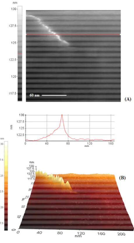
Figure 54. AFM image of compound 1-SWNT ... 82
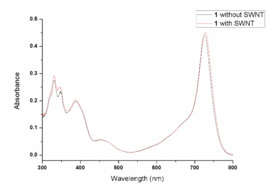
Figure 55. Absorbance spectrum of SWNT-adsorbed compound 1 in isopropanol. ... 83
Figure 56. Bleaching of 50 µM DPBF in isopropanol in the presence of 62 nM SWNT-adsorbed compound 1. ... 84
Figure 57. Absorbance of DPBF in isopropanol at 411 nm without compound 1, in the presence of compound 1 only and in the presence of
compound 1 non-covalently attached to SWNT. ... 85 Figure 58. Excitation spectra of compounds 21, 23, 24 and 25 ... 88 Figure 59. Absorbance spectra of compounds 11, 15 and 21 ... 89 Figure 60. Emission spectra of compounds 11, 15 and 21 with equal absorbance
excited at 525 nm ... 89 Figure 61. Comparison of emissions of compound 21 excited at 525 nm and 585
nm ... 90 Figure 62. Absorbance spectra of compounds 18, 20 and 23 ... 92 Figure 63. Emission spectra of compounds 18, 20 and 23 with equal absorbance
excited at 585 nm ... 92 Figure 64. Comparison of emissions of compound 23 excited at 585 nm and 645
nm ... 93 Figure 65. Absorbance spectra of compounds 19, 20 and 24 ... 94 Figure 66. Emission spectra of compounds 19, 20 and 24 with equal absorbance
excited at 585 nm ... 94 Figure 67 Comparison of emissions of compound 24 excited at 585 nm and 645
nm ... 95 Figure 68. Absorbance spectra of compounds 11, 15, 19 and 25 ... 95 Figure 69. Emission spectra of compounds 11,19 and 25 with equal absorbance
excited at 525 nm ... 96 Figure 70. Emission spectra of compounds 15,19 and 25 with equal absorbance
excited at 585 nm ... 96 Figure 71. Comparison of emissions of compound 25 excited at 525 nm, 585 nm and 645 nm ... 97
Figure 72. Schematic representations and FRET efficiencies of compounds 21,
23, 24 and 25... 98
Figure 73.1H NMR spectrum of compound 3 ... 111
Figure 74. 13C NMR spectrum of compound 3 ... 112
Figure 75. 1H NMR spectrum of compound 4 ... 113
Figure 76. 13C NMR spectrum of compound 4 ... 114
Figure 77. 1H NMR spectrum of compound 5 ... 115
Figure 78. 13C NMR spectrum of compound 5 ... 116
Figure 79. 1H NMR spectrum of compound 6 ... 117
Figure 80. 13C NMR spectrum of compound 6 ... 118
Figure 81. 1H NMR spectrum of compound 7 ... 119
Figure 82. 13C NMR spectrum of compound 7 ... 120
Figure 83. 1H NMR spectrum of compound 8 ... 121
Figure 84. 13C NMR spectrum of compound 8 ... 122
Figure 85. 1H NMR spectrum of compound 1 ... 123
Figure 86. 13C NMR spectrum of compound 1 ... 124
Figure 87. 1H NMR spectrum of compound 9 ... 125
Figure 88 13C NMR spectrum of compound 9 ... 126
Figure 89. 1H NMR spectrum of compound 10 ... 127
Figure 90 13C NMR spectrum of compound 10 ... 128
Figure 91. 1H NMR spectrum of compound 11 ... 129
Figure 93. 1H NMR spectrum of compound 13 ... 131
Figure 94 13C NMR spectrum of compound 13 ... 132
Figure 95. 1H NMR spectrum of compound 14 ... 133
Figure 96 13C NMR spectrum of compound 14 ... 134
Figure 97. 1H NMR spectrum of compound 15 ... 135
Figure 98 13C NMR spectrum of compound 15 ... 136
Figure 99. 1H NMR spectrum of compound 16 ... 137
Figure 100 13C NMR spectrum of compound 16 ... 138
Figure 101. 1H NMR spectrum of compound 17 ... 139
Figure 102 13C NMR spectrum of compound 17 ... 140
Figure 103. 1H NMR spectrum of compound 18 ... 141
Figure 104 13C NMR spectrum of compound 18 ... 142
Figure 105. 1H NMR spectrum of compound 19 ... 143
Figure 106 13C NMR spectrum of compound 19 ... 144
Figure 107. 1H NMR spectrum of compound 20 ... 145
Figure 108 13C NMR spectrum of compound 20 ... 146
Figure 109. 1H NMR spectrum of compound 21 ... 147
Figure 110 13C NMR spectrum of compound 21 ... 148
Figure 111. 1H NMR spectrum of compound 22 ... 149
Figure 112. 1H NMR spectrum of compound 23 ... 150
Figure 113 13C NMR spectrum of compound 23 ... 151
Figure 115. 1H NMR spectrum of compound 25 ... 153
Figure 116. ESI-HRMS of compound 3. ... 154
Figure 117. ESI-HRMS of compound 4. ... 155
Figure 118. ESI-HRMS of compound 5. ... 155
Figure 119. ESI-HRMS of compound 6. ... 156
Figure 120. ESI-HRMS of compound 7 ... 156
Figure 121. MALDI-MS of compound 8 ... 157
Figure 122. MALDI-MS of compound 1. ... 157
Figure 123. ESI-HRMS of compound 11 ... 158
Figure 124. ESI-HRMS of compound 14 ... 158
Figure 125. ESI-HRMS of compound 15 ... 159
Figure 126. ESI-HRMS of compound 17 ... 159
Figure 127. ESI-HRMS of compound 18 ... 160
Figure 128. ESI-HRMS of compound 19 ... 160
Figure 129. ESI-HRMS of compound 20 ... 160
Figure 130. MALDI-MS of compound 21. ... 161
Figure 131. MALDI-MS of compound 23. ... 161
Figure 132. MALDI-MS of compound 24. ... 162
Figure 133. MALDI-MS of compound 25. ... 162
Figure 134. Fluorescence decay spectrum of 15. ... 163
Figure 137. Fluorescence decay spectrum of 21. ... 165 Figure 138. Fluorescence decay spectrum of 25 emission at 545 nm. ... 165 Figure 139. Fluorescence decay spectrum of 25emission at 675 nm ... 166
LIST OF TABLES
Table 1. Some PSs approved so far and the diseases they are used for ... 15 Table 2. Photophysical properties of dendrimers and dendrimer elements ... 87 Table 3. Lifetimes, FRET rate constants and efficiencies of compounds ... 91
CHAPTER 1
INTRODUCTION
1.1 Photodynamic Therapy
Photodynamic therapy is a relatively young, non-invasive approach to the treatment of certain diseases such as some malignant cancers, actinic keratoses, psoriasis, age-related macular degeneration, oesophageal diseases and some cardiovascular diseases.1 In this therapy, light-sensitive drugs (or photosensitizers) are introduced topically, intravenously or orally.1 After certain time of administration, usually 1 to 3 days, light of certain wavelength is exposed. This delay in light exposure maintains accumulation of photosensitizer (PS) in the region of interest up to 28:1 ratio of concentrations for tumor to normal tissue for some photosensitizers due to enhanced permeation and retention in tumor.2 Intracellular localization on the other hand, depends on hydrophobicity and charge of PS. Hydrophobic ones tend to localize in the membrane and cationic PDT agents are mainly accumulate in mitochondria.3
Activation of photosensitizer using suitable light leads to formation of reactive oxygen species including singlet oxygen (O21) from molecular oxygen which attack to nearby molecules such as lipids, proteins or DNA, depending on the location of the photosensitizer and give oxidative damage to the corresponding biological structures.4,5 This in turn, results in cellular response such as initiation of apoptosis or necrosis, shut down of vascular supply which results in hypoxia or activation of immune system.6-8 The light used for PDT can come from either a laser or other sources such as light-emitting diodes (LEDs) and should be preferably red or near IR in color since light of this color penetrates through tissues better.9
1.1.1 History of Photodynamic Therapy
Use of sun light for the treatment of certain diseases is not a recent finding, rather it was realized by Herodotes more than two thousand years ago and use of photoactive molecules for the treatment of vitiligo were described in holly book of India, Atharava-veda.10 The story of photodynamic therapy in scientific literature however, begins with Oscar Raab’s observation on toxic effects of acridine red molecule on certain bacteria in the presence of intense light.10-12 By doing control experiments, he proposed and demonstrated that presence of fluorophore is required for the corresponding light-induced toxicity. Scientists Tappeiner and Jesionek used the eosin dye for the treatment of skin cancer, thus, eosin becomes the first photosensitizer used for medical purposes.13
Following these discoveries, in 1904, indispensable involvement of oxygen in the photodynamic response is realized by Tappeiner and Jodbauer.14 However, exact mechanism of oxygen-dependent toxicity of photoactive molecules cannot be resolved until 1979, the year when electron spin resonance technique was used to monitor the generation of singlet oxygen, highly reactive excited state oxygen, by Moan et al.15
First human trial of PDT was done by Meyer-Betz on himself and extreme apses and pain was observed.16 On the other hand, first clinical application of PDT was at Roswell Park Cancer Institute in 1978 by Dougherty et al.17 Following this, in 1980 photofrin, a mixture of hematoporphyrin derivatives is approved by FDA as a photosensitizer. From that time on, a number of photosensitizers which are either porphyrin or haematoporphyrin derivative, such as HPPH, ALA, Levulan, Foscan, Metvix are approved by FDA or EU. Great success in treatment of a variety of diseases, mainly different forms of cancer is achieved.
1.1.2 Mechanism of Photodynamic Action
Generation of tremendously reactive oxygen in its lowest lying excited state by means of photoactivation of fluorophore is the crucial step in the mechanism of this therapy. The steps involved in photon induced 1O2 generation are shown with a Jablonski diagram in Figure 1. Excitation of fluorophore via photon of appropriate energy from its ground state to the first excited state is the initiation step (step 1). From this singlet excited state, relaxation to ground state vibrational level of excited electronic state occurs. From here on, there are two possible pathways apart from radiationless relaxation to the ground state: electron can fall back to its electronic ground state which gives fluorescence (step 2) or it can go into an intersystem crossing to triplet excited state (step 4). If the latter pathway is favored, such as the case in the presence of heavy atoms, triplet excited state energy can be transferred to ground state oxygen to generate reactive singlet oxygen, otherwise phosphorescence, delayed fluorescence occurs when electron falls back to ground state of the photosensitizer (step 5).9,18
Biological outcome of photodynamic therapy basically relies on the reactivity of photogenerated singlet oxygen which either leads to the formation of other reactive oxygen species or directly gives oxidative damage to cell. Due to the short life time (0.6 µs) hence diffusion distance (0.1 µm) of singlet oxygen, oxidative damage to cellular structures is expected to be initiated in the vicinity of the photosensitizer.19 For the reasons mentioned above, localization of the photosensitizer determines the targets of reactive oxygen species and mode of cell death.
1.1.2.1 Chemical Response; Oxidative Damage by
1O
2Photosensitizer mediated cytotoxicity results from two different mechanisms. In type-I reaction, excited photosensitizer directly reacts with a substrate, namely a biomolecule and form unstable radicals. These radicals further react with other substrates or molecular oxygen to generate singlet oxygen. In type-II reaction, energy is directly transferred from excited PS to oxygen to produce 1O2. Generally, it is not easy to differentiate between these two modes and both reaction types are known to be involved in photodynamic action simultaneously.6
Being a very powerful oxidant, 1O2 reacts immediately with a number of biomolecules giving rise to oxidative stress. Reaction with membrane lipids would be lipid peroxidation that alters membrane structure, integrity and fluidity. Decomposition of these peroxides produce lipid radicals, another cytotoxic danger for the cell. Other reactive oxygen species generated by 1O2 can attack free amino and thiol groups of amino acids and disrupt the folding and proper functioning of proteins.20 One reason of photoinduced increase in mitochondrial membrane permeability is thought to stem from the oxidation of disulfide histidine amino acids in membrane proteins, leading to formation of more labile membrane, permits the passage of mitochondrial constituents, induce cell death consequently.21 Formation of different radicals and reactive
compounds in each step leads to the amplification of oxidative stress in the cell.22 In the structure of DNA, dioxyribose sugar and bases, especially thymines are prone to chemical attack by hydroxyl radicals that are generated by reactions of singlet oxygen.23 These type of modifications in DNA strand result in mutations; strand breaks. In addition, cross-linking of DNA with proteins or DNA itself is also observed as a genotoxic outcome of PDT.24 Singlet oxygen also impairs the normal functioning of DNA repair enzyme, thus, each damages on DNA accumulates and triggers cell death immediately after photodynamic action.25
1.1.2.2 Biological Response
Two modes of cell death, namely, apoptosis or necrosis can be induced in response to photodynamic therapy, each having different morphological properties.26 Apart from direct cytotoxic effect, photodynamic therapy results in shutdown of vascular supplements to the tumor tissue. Immunological stimulation against cancerous regions is a long term benefit of this type of therapy as opposed to most of the other types.27
Apoptosis is programmed cell death characterized by DNA fragmentation, chromatin condensation and cell shrinkage. Molecular elements responsible for/having role in this phenomenon involve wide range of membrane and cytosolic proteins some of which are receptors or transporters. Mainly, apoptotic signals are introduced in two converging pathways: external signals are introduced to the cell through dead receptors initiated via ligand binding. This recruits some proteins to the receptor, induces the formation of death-inducing signaling complex, and activates certain caspases, cystein aspartic acid proteases such as caspase-8. Internal signals can also trigger caspase activation in response to release of cyctochrome-c and other mitochondrial apoptotic proteins. Formation of active protein complex from caspase-9, cytochrome-c, called apoptosome relays the apoptotic signal to entire
cell in an irreversible way, program cell death is implemented.19,28,29 Apoptosis in PDT can be triggered due to impairment of ion homeostasis and consequent increase in intracellular Ca+2 ion concentration. Drastic rise in Ca+2 ion concentration activates phospholipase C, protein kinase C, interferes with arachidonic acid metabolism all in turn lead to apoptosis and inflammatory responses.24
Figure 2. Biological response induced by photodynamic therapy.19
Another mode of cell death triggered by photodynamic therapy is necrosis, a more traumatic, unnatural death characterized by swelling of the cell, disruption of intracellular and plasma membranes and subsequent rupture of the cell, release the contents of the cytoplasm to the surrounding tissue. This type of cell death, together with apoptosis is the outcome of cytotoxic effect of photodynamic therapy.19
Beside its cytotoxicity to the region of application, PDT has a very distinct property that is not found in traditional chemotherapy or radiotherapy,
immune system stimulation. Oxidative damage to the elements of cell membrane decreases the integrity and phospholipids are liberated. These phospholipids are rapidly metabolized to immune stimulatory molecules such as leukotrienes.24 When either apoptosis or necrosis takes place after photodynamic action, heat-shock protein-70 (HSP70) is induced.30 Being a chaperone protein, it interacts with tumor antigens, stimulate anti-tumor response and attract neutrophils to the side of tumor. Korbelik and Sun used this property of photodynamic therapy to develop cancer vaccines, namely, bio-sample that recognize and acts against tumor cells.31 For this purpose, they inject PDT-applied cell lysates to mice, suffering from cancer. After a short time of administration, obvious regression in tumor size and healing was reported.
1.1.3 Requirements for Photosensitizers
The photosensitizer, which is introduced into the cells before light is shone onto the tissue, must have certain fundamental properties to make it suitably and successfully acting agent. Photodynamic action necessitates intrinsic ability of photosensitizer to generate reactive singlet oxygen species. Thus, specific molecules with appropriate chemical and physical properties are required such that the efficacy of singlet oxygen generation thus photodynamic action should be considerably high.
Spin forbidden transition from triplet ground state of molecular oxygen to singlet excited state is enhanced with increased spin-orbit (SO) coupling since coupling of spin angular momentum with orbital angular momentum mix the singlet and triplet states such that triplet state has certain singlet character. This in turn, makes spin forbidden singlet-triplet transitions possible. Spin-orbit Hamiltonian term is proportional to fourth power of Z, presence of heavy atom increases spin-orbit coupling thus spin forbidden singlet-triplet radiationless transition. SO-Hamiltonian is formulated as below.32, 33
where e is electron charge, Z is atomic number, ao is Bohr’s radius, m is mass of electron, c is speed of light, n is principle quantum number, L and S are angular momentum and spin operators respectively.
This phenomenon is studied experimentally in BODIPY dyes and it was verified by O’Shea et al. that presence of two bromine atom in the structure of molecule increases the efficacy of the photosensitizer up to thousand folds. Hence, photosensitizers having heavy atoms in their structures exhibit better singlet oxygen generation capability.
Most photosensitizers degrade in the presence of light, so called photobleaching, mainly due to reactive oxygen species generated as a part of PDT action.35 For this reason, to maintain photodynamic character photosensitizers have to be photostable.
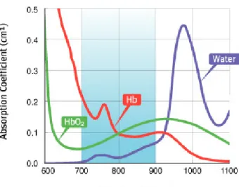
Due to the presence of absorbing molecules in the living organisms, tissue penetration depth of light at different wavelength differs considerably in different regions of the body. Certain aromatic compounds such as amino acids tyrosine, phenylalanine and tryptophan absorb near UV region, different regions of visible light are absorbed by melanin, collagens, nicotinamide, flavins, and haemoglobins. Beyond 1150 nm, light penetration decreases substantially due to absorbance of water. Considering the absorbance of these and other biomolecules, maximum penetration is achieved with light of the range 620-850 nm, so called therapeutic or pharmaceutical window of the body. Thus, design or choice of photosensitizer should be accordingly in order to achieve sufficient intensity of light in the region of therapeutic action, it must absorb light within this given wavelength range strongly so that it can efficiently produce the reactive oxygen species.3, 9, 37
Figure 3. Therapeutic window of the body, absorbance of oxy-hemoglobin (HbO2),
deoxy-hemoglobin (Hb) and water.36
Beside its photophysical properties already revealed, the sensitizer has other requirements for biological application such as biocompatibility. It should not have dark toxicity; in other words, has to be ineffective until light is exposed to it. In addition, an important necessity for practical medical use is that it should be water-soluble and there should be no immunological reaction against.
1.1.3 Photosensitizers in Literature
First generation PS are mainly porphyrin derivatives such as photofrin, hematoporphyrin which do not have strong absorption in the therapeutic window of the body.38 Phthalocyanine related sensitizers and synthetic chlorins are more promising when their absorptions are compared (Figure 4).38 Xanthanes such as fluorescein, eosin and Rose Bengal are common singlet oxygen generating organic compounds.39 Perylenediimide dyes have high quantum yield and absorption maxima which can be shifted to longer wavelengths by proper modifications.39 The only drawback of this dye is its low
solubility in protic solvents. BF2 chelated tetraaryl azadipyrromethene dyes (aza-BODIPY), as extensively studied by O’Shea et al, have sharp absorption in therapeutic window of the body and show highly efficient PDT character.34, 40 Cyanine dyes, hypericin, squaraines, texaphyrins, fullerenes were also used as sensitizer.38, 39, 41
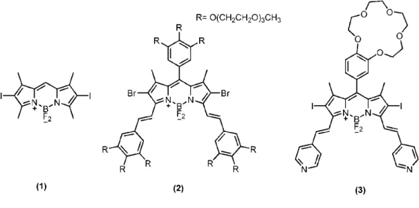
Figure 5. based photosensitizers in literature. Compound 1 is the first
BODIPY-based photosensitizrs reported by Nagano et al., compound 2 and 3 were reported by Akkaya et
al.42, 43, 44
Recently, borondipyrromethene (BODIPY) dyes become attractive in this era when their high extinction coefficients and photostabilities are considered.42, 43, 45 Possibility of multiple and facile chemical modifications on this molecule allow attachment of chemical groups that would enable selective tumor targeting, water solubility together with groups attached to increase photodynamic action (Figure 5).
One impressive example of such BODIPY photosensitizer was synthesized by Akkaya et al.44 This photosensitizer, compound 3 contains chemical groups that detect the acidity and sodium concentration of the medium, namely, singlet oxygen generation property of the molecule is under the control of these two parameters (Figure 5 and Figure 6). Protonation of pyridine groups in acidic media causes a bathochromic shift in the absorbance. When light of 660 nm is introduced, only molecules with protonated pyridine groups are excited and show photodynamic action, provided photo-induced electron transfer (PET) is blocked by Na+ binding to crown ether moiety. Thus, only in cancer tissues where sodium concentration is high and pH is low, 1O
maintained.46, 47 Nagano et al. recently reported a BODIPY derivative that selectively inactivates protein after binding to its hydrophobic cavity.48
Figure 6. Smart PS seeking for cancer parameters.44
Nowadays, PDT with controlled generation of singlet oxygen is becoming more and more important. There are some recent examples in literature that rationally focus on this issue beside the Akkaya’s photosensitizer given above. One such example relies on Watson-Crick base pairing of DNA strands in which 5’ end of one strand is linked to the photosensitizer whereas 3’ end of complementary strand hold a quencher.49 When there is no quencher-free complementary strand, ability of photosensitizer to generate singlet oxygen is abolished due to the presence of quencher in close proximity to enable Förster resonance energy transfer (FRET, through space) from PS to quencher.50-52 However, in the presence of a number of target-DNA around, statistically, the chance of pairing with quencher-free DNA increases which in turn increases the singlet oxygen mediated toxicity. This type of dual system where outcome is dependent of hybridization or proximity is called molecular beacon.53
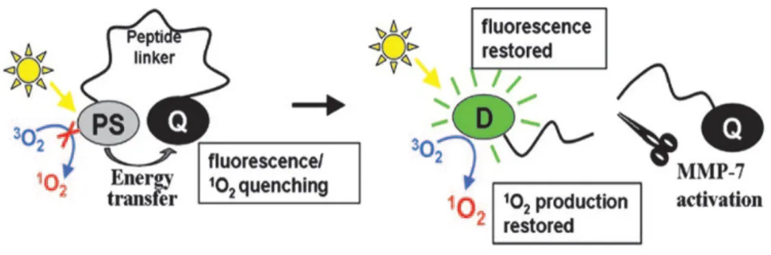
Figure 7. Cancer selective activation of PS through release of quencher by protease
MMP7.54
One other molecular beacon designed to control photodynamic action is published by Zheng et al. and Tung et al. separately, and depends on cancer specific expression of proteases (Figure 7).54, 55 In the case of Zheng’s research, photosensitizer is chemically linked to a quencher molecule called Black Hole Quencher 3 through specific peptide spacer. This spacer has special amino acid sequence, the sequence specifically recognized and cleaved by matrix metalloproteinase-7, MMP7. This enzyme is known to be over expressed in certain cancer types such as colon, pancreas and breast cancers, hence, quencher free photosensitizer is ready to generate cytotoxic agents only in these specific tissues.54, 56
The example shown in Figure 8, based on the quenching of the photosensitizer, chlorine-e6 when it comes close to the surface of single walled carbon nanotube (SWNT).57 An aptamer attached to the photosensitizer favors this interaction. However, when aptamer preferentially binds to the target, PDT agent detaches from the SWNT, gains its ability to generate singlet oxygen. Thus, the ability to generate singlet oxygen is maintained only in the presence of target molecule.
1.1.5 Clinical Applications
Starting with the first promising medical trial in 1970s photodynamic therapy is widely used in a number of diseases. Most of the photosensitizers approved so far and the diseases they are used for are listed in Table 1. Considering the exigency of conveying light to the region of treatment, dermatologic applications became the first type of trials. In these first treatments, nearly all primary skin cancers such as basal cell carcinomas showed complete response whereas secondary cancers that are formed as a result of breast, colon or endometrium cancers, 80% response were reported.58
Age-related macular degeneration is an ophthalmic disease to which PDT is applied. A photosensitizer called Verteporfin is approved as a PDT agent and placebo controlled trials demonstrated that the treatment maintains a stabilized vision afterwards.59 One other ocular use of PDT was in treatment of choroidal hemangiom, in other words eye cancer. It has been shown in a 10-case study that PDT results in regression of the tumor and reduction in the vascular structures.60
Table 1. Some PSs approved so far and the diseases they are used for.38
Photosensitizer Trade Name
Approval λλλλ(nm) Area of Use
Porfimer sodium Photofrin 1998 FDA 630 Lung, Barrett’s esophagus ALA-PpIX Levulan Keratastick 1999 FDA 405 635 Actinic Keratosis Methyl aminolevulate-PpIX Metvix 2004 FDA 405 635 Actinic keratosis Hexyl aminolevulate-PpIX Hexvix 2005 EU 405 Detection of bladder tumors BPD-MA Verteporfin, Visudyne 2000 FDA 689 Choroidal neovascularization mTHPC Foscan 2001 EU
652 Head and neck, prostate, pancreas, esophagus,
mesothelioma Motexafin Lutetium MLu, Lutex,
Lutrin
Phase I 732 Prostate, atherosclerosis
Pd-bacteriopheophorbide
Tookad Phase I 762 Prostate
Taloporfin sodium LS11 Phase I&II
664 Choroidal
neovascularization, liver and colorectal metastasis
Silicon
pthalocyanine-4
In head and neck cancers, those of cancers develop in oral cavity, the pharynx, the nasal cavity and larynx, PDT is preferred as opposed to other conventional radiotherapy and chemotherapy because of higher cure rates and better cosmetic outcome.61 Photosensitizers, photofrin and foscan are approved to be used in this type of applications. Treating brain tumors with other common surgical methods is challenging due to the risk of giving damage to nearby essentially important structures. That is the reason why PDT is used as a post-surgical follow-up procedure for these types of cancers. In late 1990s, Stummer et al. were succeeded in complete removal of tumor in malignant glioma tissue.62 Complete recovery of visual field, a 46% reduction in tumor size in pituitary adenomas within two years is also reported.63
Animal trials and small group patient trials in some cardiovascular diseases such as atherosclerotic plaque, hyperplasia, restenosis and cancers such as gastroenterological, mesothelial and gynecological cancers also give very promising results.64 It can be said that PDT can be used in the treatment of these diseases as well in the near future.
1.2
Carbon Nanotubes
Carbon nanotubes (CNT) are one dimensional cylinderical allotropes of carbon which are formed by rolling of single or many sheets of graphite with a diameter of a few nanometers. The one with single layer is called single-wall carbon nanotube (SWNT) and those with multiple layers are called multi-wall carbon nanotube (MWNT). First discovered by Iijima et al. carbon nanotubes attract enourmous attention as nanomaterial because of their unique electronic, mechanical and structural properties.65, 66 Because of its high electron conductivity, it is used to develop molecular electronic devices and their use in biomedical area is increasing.66-68 Carbon nanotubes can be functionalized to modify electronic properties or to make them better delivery system for drugs or related therapeutic agents.
1.2.1 Modifications of Carbon Nanotubes
Although CNTs are very promising for a number of research and application, they suffer from severe solubility problem such that they immediately form bundles and aggregates through strong van der Waals interaction between the side walls.69This drawback can be handled via covalent or non-covalent functionalization of CNTs which interfere with bundle formation and increase solubility. In order to preserve electronic properties by maintaining sp2 hybridization of carbons and for the simplicity of procedure non-covalent modifications are preferred.
1.2.1.1 Covalent Modifications of Carbon Nanotubes
Covalent modification of carbon nanotubes is quite difficult due to lack of solubility in any kind of solvent. On the other hand, it is possible to oxidize ends of CNTs to carboxylic acid by means of refluxing in concentrated nitric acid.71-73 This procedure also induces defects on the walls of CNTs which affects their electronic properties but not a concern for most of the biomedical applications.74 Carboxylic acid bearing CNTs can be further modified using well-known chemical methods to increase their solubility and to functionalize for specific use. Besides, having higher curvature, thus strain, CNTs possess greater reactivity compared to flat graphene sheets.75 This strain-dependent partial reactivity allows chemical functionalization on the side walls of CNTs through nitrene addition, hydrogenation, arylation, 1, 3-dipolar cycloaddition, fluorination or alkylation.76-84
1.2.1.2 Non-covalent Modifications of Carbon Nanotubes
Modification of CNTs without any change in their structure or electromechanical properties are feasible through non-covalent modification which can be done either through hydrophobic interactions of surfactants or through wrapping of polymers, DNA on the walls of CNTs.85-89 In addition, a number of aromatic compounds adhere on the side walls of CNTs through π-stacking interactions (Figure 9).70 Among such compounds, interaction of pyrene with CNTs was well studied.90, 91 The stability against desorption make pyrene-CNT complex very promising for biomedical applications as well as molecular electronics. Interaction of pyrene with CNTs can be easily characterized using quenching of pyrene emission.92, 93
blue dye.94-96 The main advantage of non-covalent modifications is the lack of requirement of harsh conditions as in the case of most of chemical modifications. Simple sonication is enough for adherence of polymers or aromatic moieties on the walls of CNTs.85-96
1.2.2 Biomedical Applications
Carbon nanotubes are appropriate tool for biomedical applications because of their facile internalization into cells.97 Besides, no significant toxicity was reported although a number of researches were done on this subject.98-104 CNTs are mainly used as delivery vehicle for proteins, nucleic acids for therapeutic purposes or certain radio-labeled moieties and fluorescent molecules for imaging purposes.68 Interesting researches where CNTs were used as substrate for neurons, was also done where differently functionalized CNTs induce different branching as the neurons grow.105 Carbon nanotubes carrying different anticancer drugs and photodynamic therapy reagents are also reported by others.57, 106, 107
1.2.2.1 Biodistribution and Cytotoxicity
Biomedical use of carbon nanotubes became more and more popular within last ten years due to its facile preparation as delivery systems. In order to be used as a real delivery system or a biomedical tool for other bioapplications, toxicity, biocompatibility and possible interference with biochemical and cellular functions have to be investigated extensively. For this concern, a number of researches were done either to determine the distribution of CNTs throughout the body, retention, excretion or possible pathological response induced within the organisms.
In an attempt to determine biocompatibility and cytotoxicity Ausman et al. prepared different water-dispersible SWNTs and examined the role of degree of functionalization of SWNT for biocompatibility in human dermal fibroblast cell culture.98 As a consequence, use of solubilized nanotubes rather than naked ones are recommended in order to prevent toxicity. Further, Dumortier, Prato and Bianco et al. reported that solubilized carbon nanotubes do not abolish cell viability nor interfere with proper functioning of primary immune cells.99
Figure 10. Biodistribution and rapid clearance of carbon nanotubes.100
Biodistribution of CNTs and clearance rate from the body of the mice were examined in two different studies and consistent results were obtained.100, 101Although CNTs were accumulated in certain parts such as kidney and muscle right after administration, they are cleared rapidly within a few hours and excreted through feces or urine (Figure 10).100 Circulation half life of CNTs was determined to be 3.5 hours and 5.5 hours for diethylenetriamine pentaacetic acid
and glucoseamine functionalized CNTs respectively. When long term pathologic effects of CNTs are considered, no sufficient experiments are done yet, except from a few pilot researches. In one such research CNTs injected into the abdominal cavity of mice cause asbestos-like symptoms such as inflammation and lesion.102 Dose dependent inflammation in lung was observed in a 3 months research on rat.103 However, in a different study mice were observed for much longer time, 4 months after intravenous injection of polyethylene glycol functionalized CNTs and no significant pathogenicity was observed.104 These works again confirms that CNTs toxicity is associated with its degree of functionalization and highly soluble CNTs are required to avoid possible side effects.
1.2.2.2 SWNT as Delivery System
Considering delivery systems, the most important problem for bio-application is their internalization by cells. They require additional specific functionalization to facilite entrance into the cell. CNTs, on the other hand, are shown to be internalized into mammalian cells mainly through energy dependent mechanism, endocytosis.97, 108, 109 Moreover, by providing cell specific targeting groups CNTs can more selectively accumulate in certain tissues such as the case in the work of Dai et al.110 In this study, SWNTs carrying RGD amino acids, cancer specific integrin αβ antagonist, were prepared and the distribution of nanotubes was monitored through positron emitting 64Cu. Biological imaging using fluorophore-CNT conjugates were also done.111 Antibody conjugated non-covalently modified SWNTs were used as electronic biosensors through which disease specific biomolecules can be detected.112
Carbon nanotubes absorb near-infrared light, using this property, thermal destruction of cancer cells were achieved.113-115 In another research, controlled release and subsequent activation of photosensitizer in the presence of tumor
markers was studied (Figure 8).57 In this research, SWNT inhibit the singlet oxygen generating capability of the photosensitizer until tumor marker is present. More interestingly, Dai et al. non-covalently functionalized SWNTs using hydrophobic interaction of phospholipids with SWNT wall; small interference RNA (siRNA) was attached to phospholipids via disulfide linkage.116, 117 Reduction of disulfide bond to thiol released siRNA and successful gene silencing was observed.
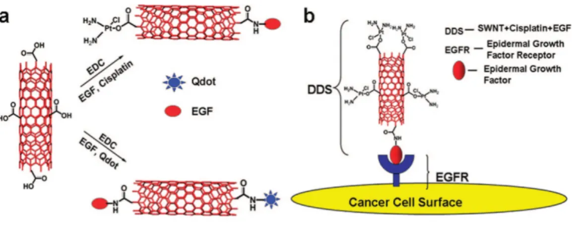
Figure 11. Targeted delivery of cancer drug using SWNT as delivery vehicle.118
Three different anticancer drug-loaded CNTs were rationally designed and delivered by two different groups. Dai and Lippard et al. tethered Pt (IV) complex on SWNT and release of toxic cis-[Pt(NH3)2Cl2] upon intracellular reduction induced tumor cell death.106 Low pH in cancer cells facilitate the reduction, thus release of active anticancer complex and there is an obvious increase in cytotoxicity of SWNT-drug conjugate compared to free drug. Same drug was used recently by other research group, where additionally epidermal growth factor (EGF) was attached to SWNTs to maintain cancer targeting (Figure 11).118 EGF conjugated, drug loaded SWNTs were internalized by cancer cells whereas cells having reduced expression of EGF receptor (EGFR) failed to internalize the SWNTs. In the research of Wong and Ojima et al.
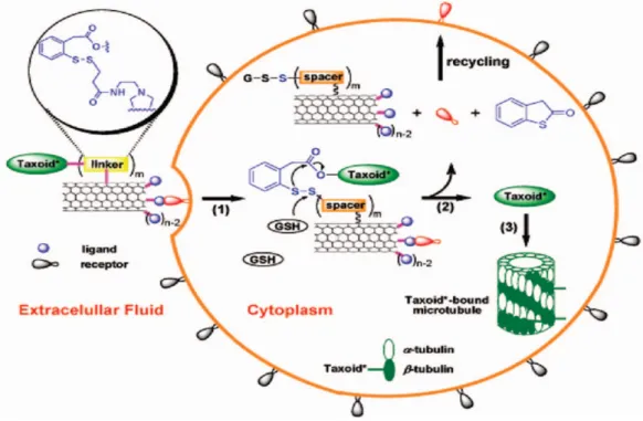
well-on the surface of the SWNT through disulfide bwell-ond.107 Gluthathione (GSH) mediated reduction of this bond in specific tissue liberates the drug and induces cell death in the vicinity (Figure 12).
Figure 12. Gluthathione mediated drug delivery using SWNT as a delivery vehicle.107
Taking their biocompatibility, non-toxic character into account and considering all the examples given above, SWNTs seem to be very promising delivery system and material for other biomedical applications.
1.3
Light Harvesting and Energy Transfer
1.3.1 Energy Transfer Mechanisms
Energy transfer is the process where energy is transmitted from a chromophore in its excited state to a different chromophore in its ground state.119 Excitation energy of the former, donor (D) is used to excite the latter, the acceptor (A) to its first singlet excited state. Energy transfer can be characterized using different approaches; comparing relative lifetimes, quantum yields, quenching of the donor emission or increase in acceptor emission would be parameters to follow. Energy transfer is affected from rate of other deactivation pathways of excited system, thus chromophores have to be suitable to compete with these pathways.119-120 Lifetime of excited state has to be longer than time required for energy transfer. There are two different types of energy transfer mechanisms called Förster and Dexter types, which are theoretically well established and experimentally verified.
1.3.1.1 Dexter Type Energy Transfer
Dexter Type, also called “through bond”, energy transfer basically relies on orbital interaction of donor and acceptor molecules leading to exchange of electrons from the highest occupied level of the donor to the lowest unoccupied level of the acceptor.121 Simultaneous exchange of ground state electrons accompanies this process (Figure 13).119 This dependency on orbital interaction restricts energy transfer to very short distances, usually less than 10 Å.120 As a consequence, energy transfer rate constant decreases exponentially with increasing donor-acceptor separation as formulated below.
k
ET= K J exp(-2R
DA/ L)
(2)
where K represents orbital interaction, J is the overlap integral between donor emission and acceptor absorbance, RDA is the donor acceptor separation and finally L is the van der Waals radii.120
Dexter type energy transfer systems were designed and synthesized with different molecules as shown in Figure 14. These Dexter systems exhibit energy transfer upon excitation at donor’s absorbance wavelength in each system. In porphyrin-based system (Figure 14A) central porphyrin was decorated with four terminal pophyrins coordinated to zinc.122 This difference in the structure allows energy transfer from the terminal porphyrins to the center through ethynyl bridge. In anthracene-BODIPY system as shown in Figure-14B, very fast energy transfer (~200 fs) from anthracene to BODIPY was observed upon excitation at anthracene’s absorbance wavelength which would be due to parallel alignment of S1 - So transition dipole moments of donor and acceptor respectively.45,123
One interesting example of Dexter type energy transfer in literature would be the one shown in Figure 14C. These ligand-metal based systems provide unidirectional energy transfer in a linear array of system which would be used in the production of molecular wires.124 In this primitive example, efficient energy transfer from Ru and Os complexes to anthracene was observed.
1.3.1.2 Förster Type Energy Transfer
In contrast to Dexter type, Förster resonance energy transfer (FRET) or through space energy transfer does not depend on orbital interaction, hence, larger separation between donor-acceptor still would be allowed to achieve energy transfer. Spectral overlap between donor emission and acceptor absorbance is essentially important together with relative orientation of transition dipoles of donor and acceptor.50,51,125 Considering the fact that, energy is not transferred through bond, rather through space; other deactivation processes affect the efficiency of energy transfer. Deactivation would be due to intrinsic photophysical properties of chromophores such as internal conversion through vibrational relaxation, quantum yield of donor or as a result of solvent refractive properties.120 The distance between donor and acceptor at which half of the excited donor energy is transferred to the acceptor is called Förster distance (Ro) and formulated together with energy transfer rate constant (kFRET) as shown below:
R
o= 9.78 x 10
3[
κ
κ
κ
κ
2n
-4Q
DJ(
λ
λ) ]
λ
λ
(3)
k
FRET=
[ 900 (ln10)
κ
κ
κ
κ
2Φ
Φ
Φ
Φ
DJ(
λ
λ
λ
λ) ] / [128 π
π
π
π
5n
4N
ττττ
DR
6 DA]
(4)
where
κ
represents relative dipole moment orientation of excited donor and ground state acceptor, n is the refractive index of the medium, QD is the quantum yield of the donor in the absence of acceptor, J(λ) is spectral overlap integral of donor emission and acceptor absorbance, τD is excited state lifetime of donor in the absence of the acceptor chromophore and finally RDA is donor-acceptor separation.1201.3.1.2.1 Determination of FRET Efficiency
FRET efficiency can be determined in a number of ways; in general, there are two different approaches, steady state and time-resolved.126 In one of the steady state approach, decrease in donor fluorescence quantum yield is used. However, in this method one should be careful to avoid so called inner filter effect which refers to reabsorption of the emitted light by the same molecule or other unexpected ones. Self quenching problem can be solved using very dilute solutions.127-128 In this method, energy transfer efficiency is formulated as shown below:
E = 1 -
Φ
Φ
Φ
Φ
DA/ Φ
/ Φ
/ Φ
/ Φ
D(5)
where ΦDA and ΦD are quantum yield of donor in the presence and absence of acceptor respectively. Excitation spectra or enhancement in fluorescence emission of the acceptor can be used to determine energy transfer in steady state approach. Corresponding equation is given below:
E = A
A(
λ
λ
λ
λ
D) / A
D(
λ
λ
λ
λ
D) * [I
AD(
λ
λ
λ
λ
Aem) / I
A(
λ
λ
λ
λ
Aem) - 1]
(6)
where AA and AD refers to absorbance values of acceptor and donor ar the maximum absorbance wavelength of donor. IAD and IA refer to integrated emission area of acceptor in the presence and absence of donor at λAem respectively.
Time resolved approach provides more accurate results since inner filter effect or errors associated with integration are lacking here. This method is based on time-resolved emission of any of acceptor or donor. If the decay of fluorescence is single exponential, FRET rate constant and FRET efficiencies can be defined as shown below:126, 129
k
FRET= 1/
ττττ
DA-1/
ττττ
D(7)
E =
ττττ
Dk
FRET/(1+
ττττ
Dk
FRET)
(8)
where τD and τDA refer to excited state decay time (lifetime) of donor in the absence and presence of acceptor respectively. More simply, FRET efficiency can be found using following equation:
E = 1 -
ττττ
DA/
ττττ
D(9)
1.3.1.2.2 Examples of FRET Systems in Literature
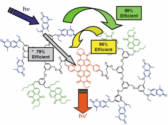
BODIPY dyes are widely used in energy transfer systems some of which are shown in Figures 15 and 16. In the example shown in Figure 15, four BODIPYs were attached covalently to perylene diimide core. In accordance with the increase in BODIPY number on the structure, extinction coefficient of the molecule at BODIPY’s maximum absorbance wavelength (526 nm) increases dramatically to 250000 M-1cm-1.130 Energy transfer efficiency was determined to be 99% with a critical Förster radius of 4.7 nm. In the second example shown in Figure 15, enhancement in emission of the core distyryl-BODIPY was observed as the number of terminal distyryl-BODIPY donors was increased in number, as expected.131
Figure 15. Some BODIPY-based Förster type energy transfer systems130-131
Figure 16. pH-controlled FRET.132
One interesting example of FRET was shown in Figure 16 where donor and acceptor distance depends on the pH of the media. In acidic conditions, FRET is abolished and donor emission was observed at 542 nm.132 In this case, the whole molecule is extended such that the distance between donor and acceptor is 7 nm. On the other hand in the contracted form, the distance decreases almost ten folds, thus, energy transfer is observed. Change in FRET efficiency upon conformational transformation is extensively used in protein labeling and enzyme dynamics.
Apart from conformational change analysis, FRET systems are used to construct chemical or biological sensors, to determine ligand-receptor interaction, membrane organization assays, to monitor hybridization of nucleic acids and a number of other applications.126
1.3.2 Light Harvesting
Scientists usually admire the biological mechanisms which are shaped through millions of years of optimization processes to yield a system, perfectly tuned to work efficiently under the rules of earth. Photosynthesis is one such marvelous system in organisms that is evolved to convert sun light into chemical energy in the form of adenosine triphosphate (ATP).133 Architectural design and synergistic functionality of elements of this energy conversion complex is inspired, hence, researches try to mimic certain parts of this system for a variety of purposes such as frequency conversion, signal amplification, artificial photosynthetic systems, dye-sensitized solar energy and molecular optoelectronic applications.134-137
Light harvesting (antenna) complex simply means array of different chromophores with different but mutual spectral properties interacting photophysically to funnel energy in certain part of the complex.138 X-ray crystallographic structure and functionality of antenna complex in purple bacteria were well-studied and a number of artificial systems were designed and synthesized.139
1.3.2.1 Light Harvesting in Purple Bacteria
In purple bacteria, extensive study on light harvesting complex and subsequent redox reactions were done. Femtosecond energy transfer between units allows channeling of light energy to the core structure called reaction center. This reaction center initiates the redox processes leading to generation of proton gradient and release of oxygen at the end.140
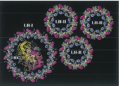
Figure 17. Antenna system in purple bacteria.141
Antenna system in purple bacteria composed of approximately 250 chlorophyll (BChl a) pigments and carotenoids having slightly different spectroscopic properties.141 As shown in Figures 17 and 18, energy is transferred from outer LH-III comlex to the inner reaction center. Hopping energy is either within the complex (dashed lines) or between different complexes (solid line) as shown in Figure 18. Although most purple bacteria have LH-I, LH-II complexes and reaction center, not all have LH-III complex.141
Within the LH-II complex, there are two different chlorophylls absorbing at 800 and 850 nm (B800 and B850 respectively). Rapid energy transfer from B850 (green) to B800 (blue) within 700 fs occurs.140-141 In all complexes, carotenoids contribute to harvesting by transferring its energy to exciton states of the B850 with 100% efficiency. These exciton states are formed as a result of interaction of intimately arranged chlorophylls. Both Dexter and Förster type mechanisms are involved in whole light harvesting processes.141
1.3.2.2 Artificial Antenna Systems
Artificial antenna complexes that resemble biological counterparts in organization and light harvesting were published. These systems mimic the circular arrangement of pigments in LH-II complex of purple bacteria. One such example is shown in Figure 19, twelve porphyrins are assembled noncovalently to form circular array where maximum separation, namely radius of antenna is 4.1 nm.142
In this synthetic system, no protein matrix assistance is required as in the case of biological antenna since chromophores readily self-arrange through coordination of imidazolyl to Zn at the core of porphyrin to form perfect circular geometry. Thus, in this example “slipped-cofacial” placement which is crucial in the accomplishment of antenna is mimicked.142
Figure 20. Artificial antenna and reaction center.143
One very exciting work was published by Tkachenko and D’Souza et al. and shown in Figure 20.143 Primitive but entire mimicry of photosynthetic system was constructed with an energy donor BODIPY, acceptor Zn-porphyrin two of which resembles antenna part of biological counterpart and finally an electron acceptor fullerene self-assembled to other part. Fullerene corresponds to reaction center, accepts electron from Zn-porphyrin and charge separation persists quite long time.143