Isı Bilimi ve Tekniği Dergisi, 39, 2, 101-110, 2019 J. of Thermal Science and Technology ©2019 TIBTD Printed in Turkey ISSN 1300-3615
PERFORMANCE ASSESSMENT OF COMMERCIAL HEAT PIPES WITH SINTERED
AND GROOVED WICKS UNDER NATURAL CONVECTION
Atakan ATAY*, Büşra SARIARSLAN*, Yiğit F. KUŞCU*, Samet SAYGAN**, Yiğit AKKUŞ**, A. Türker GÜRER**, Barbaros ÇETİN* and Zafer DURSUNKAYA****İ.D. Bilkent Üniversitesi, Makine Mühendisliği Bölümü, 06800 Çankaya, Ankara **ASELSAN A.Ş. Haberleşme ve Bilgi Teknolojileri Sektör Bşk., 06370 Yenimahalle, Ankara
***Orta Doğu Teknik Üniversitesi, Makina Mühendisliği Bölümü, 06800 Çankaya, Ankara (Geliş Tarihi: 14.08.2018, Kabul Tarihi: 20.03.2019)
Abstract: Heat pipes are widely used in thermal management of high heat flux devices due to their ability of removing
high heat loads with small temperature differences. While the thermal conductivity of standard metal coolers is approximately 100–500 W/m.K, effective thermal conductivities of heat pipes, which utilize phase-change heat transfer, can reach up to 50,000 W/m.K. In industrial applications, commercially available heat pipes are commonly preferred by thermal engineers due to their low cost and versatility. Thermal performance of a heat pipe is functions of heat pipe type and operating conditions. Selection of the appropriate heat pipe complying with the operating conditions is critical in obtaining satisfactory thermal management. One key point for the utilization of heat pipes is to avoid dryout operation condition in which heat pipes operate no more at the desired heat transport capacity. In the current study, the performance of cylindrical heat pipes with sintered and grooved wick structures, which are among the most commonly used types, is experimentally tested at different heat loads, gravitational orientations and ambient temperatures. Dryout limits of the heat pipes are determined and the relationship between the dryout onset and operating conditions is elucidated. The results reported in the present study are expected to guide thermal engineers for the proper selection and operation of conventional heat pipes.
Keywords: Heat pipe, sintered wick, grooved wick, dryout, natural convection, coolant temperature.
SİNTERLİ VE OLUKLU FİTİL YAPILARINA SAHİP TİCARİ ISI BORULARININ
DOĞAL TAŞINIM ALTINDA PERFORMANSLARININ SINANMASI
Özet: Isı boruları, yüksek ısı akılarını küçük sıcaklık farkları ile uzaklaştırabilme yeteneklerinden dolayı, yüksek ısı
akısına sahip cihazların termal yönetiminde yaygın olarak kullanılmaktadır. Standart metal soğutucuların ısıl iletkenliği yaklaşık 100–500 W/m.K iken, ısı transferi için faz dönüşümü prensibinden faydalanan ısı borularının ısı iletkenleri 50,000 W/m.K 'e kadar ulaşabilmektedir. Uygun maliyetleri ve çok yönlü kullanımları sebebiyle ticari olarak mevcut olan ısı boruları termal tasarım yapan mühendisler tarafından endüstriyel uygulamalarda sıklıkla kullanılmaktadır. Isı borularının termal performansı tipine ve operasyon koşullarına göre değişmektedir. Sağlıklı bir termal yönetim için operasyon koşullarına uygun olacak şekilde uygun ısı borusu tipinin seçilmesi önemlidir. Isı borusu kullanımında en önemli nokta ısı borusunun kurumasının engellenmesidir, çünkü ısı borusunda kurumanın başlaması ile ısı borusu artık istenilen ısı taşıma kapasitesine ulaşamamaktadır. Bu çalışmada, en yaygın kullanılan tipler olan sinterlenmiş ve oluklu fitil yapısına sahip silindirik ısı borularının performansı, farklı ısı yüklerinde, yer çekimi konfigürasyonlarında ve ortam sıcaklıklarında deneysel olarak test edilmiştir. Bu çalışmada ısı borularının kuruma limitleri belirlenmiş ve kuruma başlangıcı ile çalışma koşulları arasındaki ilişki açıklığa kavuşturulmaya çalışılmıştır. Çalışmada elde edilen sonuçların ısıl tasarım mühendisleri için doğru ısı borusu seçiminde ve ısı borusunun doğru kullanımında bir kılavuz niteliği taşıyacağı düşünülmektedir.
Anahtar Kelimeler: Isı borusu, sinterli fitil, oluklu fitil, kuruma, doğal taşınım, soğutucu sıcaklığı.
INTRODUCTION
Recent developments in micro-fabrication techniques and micro-electro-mechanical system (MEMS) technologies allow the packaging of billions of transistors in a small silicon area on a chip (Garimella and Harirchian, 2013). Thermal management of these high performance electronic components becomes challenging due to the high heat dissipation from a
relatively small area. Efficient cooling techniques are essential ingredient to secure the proper operation of these devices without any deterioration of performance. Conventional single-phase cooling methods are not appropriate due to high temperature difference and pumping power needs. Phase-change based cooling methods, on the other hand, is promising due to high latent heat of vaporization, which enables conveying high amount of heat from a heat source to a heat sink with a
small temperature difference. Heat pipes and vapor chambers have been widely utilized in the thermal management of electronics for many years due to their distinctive advantages. These devices are capillary driven and work passively without any external assistance, which eliminates any need for pumps. Therefore, they are energy efficient and durable. Moreover, capillary pumping enables the operation even in the absence of or against gravity. Furthermore, these devices are suitable for extreme miniaturization, which makes them excellent candidates for the chip level cooling solutions by the direct integration to semiconductor materials (Peterson et
al., 1993; Harris et al., 2010; Kundu et al., 2015; Akkus et al., 2019). Vapor chambers are generally utilized to
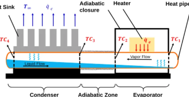
remove hot spots due to their ability of conveying the localized heat from a source to a large-area heat rejection surface (Weibel and Garimella, 2013). Heat pipes function as superconductors to transfer the heat away from the source (Faghri, 1995; Reay et al., 2014). The current study investigates the dryout characterization of conventional cylindrical heat pipes. Working mechanism of a conventional heat pipe is demonstrated in Figure 1, where the operation of the heat pipe is illustrated together with the schematic representation of the experimental setup. Liquid vaporizes at the evaporator section by adsorbing the energy transferred from the heat source. The resulting vapor moves towards the other end of the heat pipe due to the gas pressure gradient. When the vapor approaches to the cold end of the heat pipe, it starts to cool down and condenses to liquid phase. Then the condensate is passively pumped to the evaporator by the capillary action provided by the wick structure.
There exists numerous heat pipe types such as conventional cylindrical/flat heat pipes, micro heat pipes and loop heat pipes (Reay et al., 2014). Moreover, these heat pipe types can be manufactured with different geometries and/or different wick structures. A suitable selection of the heat pipe depends on the application. For instance, loop heat pipes are preferred in space applications, since they are less sensitive to the change of orientation in the gravitational field (Maydanik, 2005). In terrestrial applications, particularly in the cooling of mobile electronic devices, conventional heat pipes have been used for many years. While the geometry of the heat pipe is generally determined by the physical constraints of the electronic device, wick structure is chosen based on different factors such as the applied heat load and gravitational orientation of the heat pipe (Faghri, 1995).
Figure 1. Schematic of the heat pipe working mechanism and the heat pipe assembly used in the experiments. Locations of thermocouples are shown by the abbreviation TC. Dashed-lines represent the thermal insulation.
Three basic wick structures generally utilized in conventional heat pipes are sintered, mesh, and grooved wicks. Although sintered wicks are composed of micron-scale grains, which provide high capillary pumping, their restricted permeability leads to high flow resistance. Permeability of grooved wick structures, on the other hand, is higher. However, their capillary pumping ability may become insufficient especially during adverse gravity operation. Mesh wicks exhibit intermediate performance between sintered and grooved structures in terms of permeability and capillary pumping ability (Sauicic et al., 2000). In the present study, the performances of commercially available most common heat pipes having sintered and grooved wick structures are investigated. Microscopic images of the heat pipe cross sections of interest can be seen in Figure 2. It should be noted that sintered heat pipe functioned properly during the tests despite the non-homogenous distribution of the sintered layer along the inner heat pipe wall (see Figure 2b), which might possibly affect the performance of the heat pipe.
In order to secure the proper functioning of a heat pipe, dryout possibility of the liquid at the evaporator region should be eliminated. During the operation of a heat pipe, viscous forces acting on the liquid during the axial flow is compensated by the capillary action. If the heat load applied to the heat pipe exceeds a certain threshold, the balance between viscous and capillary forces is established with the presence of a dry region at the evaporator (Alijani et al., 2018). Dry region does not necessarily imply a catastrophic failure. The heat pipe can still operate with the presence of partially dry regions (Alijani et al., 2018; Alijani et al., 2019). However, dry regions lead to increasing local temperatures, which eventually increases the average temperature of the evaporator region. This situation is undesirable for a heat source, which is to be cooled, since the temperature of the source would also increase due to the elevated temperature of evaporator. Therefore, selection of the suitable wick structure and application of optimum operating parameters are vital to achieve efficient functioning of the heat pipe.
Condenser Adiabatic Zone Evaporator
Liquid Flow
Vapor Flow
Heat Sink Adiabatic
closure
Figure 2. (a) Cylindrical heat pipe with grooved wick structure. (b) Cylindrical heat pipe with sintered wick structure. (c) Close-up view of cylindrical heat pipe with sintered wick structure.
The performance of a heat pipe operating under different gravitational orientations is directly linked to its wick structure. Explicit effect of different gravitational orientations was investigated for different wick structures and sintered wick structure was demonstrated to be less effected by the adverse gravity operation, while grooved one experienced a severe performance loss (Loh et al., 2005). On the other hand, heat pipe with grooved wick structures exhibited superior performance for horizontal and gravity assisted conditions (Loh et al., 2005). The reason of this behavior lies in the fact that less permeable sintered wick leads to higher viscous losses during horizontal operation, where the capillary pumping ability of both wicks are already adequate. However, during the operation against gravity, grooved wick cannot sustain enough pumping to overcome the gravitational loss, while sintered ones can manage it due to its higher capillary pumping ability. To combine the advantages of high permeable grooved wicks and high capillary pumping providing sintered wicks, many studies focused on the potential benefits of hybrid wick structures (Li et
al., 2013; Jiang et al., 2014a; Jiang et al., 2014b; Khalili
and Shafii, 2016; Li et al., 2016). A compound structure composed of grooved and sintered wick structures was proposed by Li et al. (2013). They theoretically and experimentally demonstrated that compound structure both reduced the liquid backflow resistance and increased the capillary limit. A composite wick, containing porous sintered powder structure and axial micro-crack channels, was developed for electronics cooling (Jiang et al., 2014a, Jiang et al., 2014b). While the heat pipe with composite wick structure had a higher transfer limit, its thermal resistance was between that of grooved and sintered wick flattened heat pipes (Jiang et
al., 2014a). Optimal wick parameters were determined
for different gravitational orientations (Jiang et al., 2014b). Performance of a conventional sintered heat pipe was compared with a heat pipe having one third sintered wick by Khalili and Shafii (2016) and they reported that partly sintered wick had lower thermal resistance and was less affected by the gravitational changes. Grooved, sintered, sintered-grooved composite, and grooved with half sintered length wick structures were tested under various centrifugal accelerations, which mimiced adverse gravity effect on heat pipes (Li
et al., 2016). While sintered-grooved composite wick
exhibited best thermal behavior, its performance was reported to be noticeably affected by centrifugal acceleration.
To remove the heat from the heat pipe at the condenser zone, almost all of the studies have used cooling baths,
i.e. forced liquid convection, except a few studies, where
natural convection of air was utilized (Sauicic et al., 2000; Lv and Li, 2017; Atay et al., 2017). Only the effect of the coolant temperature on the working performance was investigated in studies, which used forced liquid convection for the cooling of condenser region (Loh et
al., 2005; Peyghambarzadeh et al., 2013; Jiang et al.,
2014a; Bertoldo Junior et al., 2015). The temperature differential between the evaporator and condenser was reported to decrease for higher ambient temperatures by Loh et al. (2005) and Peyghambarzadeh et al. (2013). Similarly, an increase in temperature of the cooling liquid was reported to allow the heat pipe to transport higher amounts of heat without the occurrence of dryout phenomenon (Bertoldo Junior et al., 2015). On the other hand, thermal resistance and heat transfer limit of porous composite wick flattened heat pipe were adversely affected by the increase of coolant temperature in another study (Jiang et al., 2014a). Although forced convection provides higher heat transfer coefficient with respect to natural convection, utilization of pumps and/or fans is not always possible due to the size and portability requirements of electronic devices. Therefore, natural convection from extended surfaces becomes a viable option to cool down the condenser section of heat pipes for many applications. However, studies which assess the thermal performance of heat pipes with natural convection, are limited in the literature. The present study investigates the dryout limits of the most commonly used, commercially available cylindrical heat pipes with grooved and sintered wick structures cooled by natural convection, at different heat loads, gravitational orientations, and coolant temperatures. To the best of knowledge of the authors, the effect of coolant temperature is investigated extensively for the first time in the literature for heat pipes, which are cooled by natural convection. One of the objectives of the present study is to provide technical data for the realistic industrial applications of heat pipes and to emphasize the proper utilization of heat pipes for thermal management by thermal design engineers.
MATERIAL AND METHODS Experimental Setup
A slidable test assembly adjustable in length is designed and manufactured for the performance tests of cylindrical heat pipes with different lengths. Schematic of the heat pipe assembly is shown in Figure 1. A resistance heater (51.1Ω) powered by a direct current (DC) power supply is attached to the evaporator side of the heat pipe by means of an intermediate metal plate. To ensure that all the heat dissipated by the heater is transferred to the heat pipe, the heater and intermediate metal plate are covered
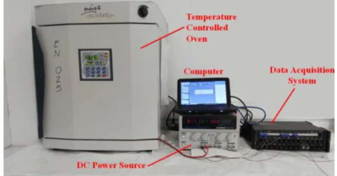
with a plastic closure filled with glass wool. In the condenser part, the heat carried by the heat pipe is transferred to an aluminum extended surface (heat sink) and heat is removed from the heat sink by natural convection. The region between the evaporator and condenser (adiabatic zone) is thermally insulated by wrapping glass wool around the heat pipe outer wall to prevent heat loss at the adiabatic zone. Two copper cylindrical heat pipes (manufactured by Enertron Inc.) with grooved and sintered wick structures, with a dimension of 200 mm in length and of 3 mm in diameter are utilized during experiments. The working fluid of the heat pipes is water. The temperature distribution along the heat pipe is measured by four T-type thermocouples. The thermocouples are located at both ends of the evaporator and condenser sections. Positions of thermocouples can be seen in Figure 1. Data received via thermocouples is recorded using Digital I/O DAQBook data recorder. Heat pipe assembly is placed within a temperature controlled oven during experiments. A computer is used to monitor the changes in the temperatures. The experimental setup is shown in Figure 3.
Figure 3. The experimental setup.
Experimental Method
Experiments are initiated with low heat loads (usually around 1.0W) to eliminate the possibility of an early dryout. During the experiments, temperatures are continuously monitored by the computer interface and the data is recorded at every 5 seconds. At each heat load, care has been taken to ensure that sufficient time is allowed for the system to reach steady operation. Since the natural convection mechanism is used to remove the
heat from the system, long operation durations are needed for the stabilization of system temperatures. While the test periods last ~1–2 hours for heat loads sufficiently lower than the dryout onset, experiments are prolonged for ~3–4 hours in order to ensure that the system becomes stable at the heat loads close to the dryout onset. Evaporator temperatures are closely monitored during experiments to terminate them in the case of a dryout condition. The temperature difference between the two ends of the evaporator, (𝑇1− 𝑇2), is selected as the dryout indication parameter and the experiments are terminated when this difference exceeds the threshold, 1.0℃. Variation of evaporator temperatures during a sample dryout event can be seen in Figure 5. Constant temperature of the ambient is secured during the experiments. Heat pipe assembly is placed at the base of the temperature controlled oven during horizontal experiments (see Figure 4a). For the vertical tests, the heat pipe assembly is mounted to the side wall of the oven. When the condenser of the heat pipe is positioned at the top, gravity assists the liquid feeding to the evaporator (see Figure 4b), which is called as gravity assisted operation in this study. The opposite case is called as gravity resisted operation (see Figure 4c). Experiments are carried out at three different gravitational orientations: horizontal, vertical-gravity assisted and vertical- gravity resisted. During horizontal experiments, the effects of wick structure and ambient (coolant) temperature on the dryout limit are investigated. In vertical experiments, the effects of favorable and adverse gravity are tested on the heat pipes with sintered and grooved wick structures. The thermal resistance values at each heat load are calculated using the following equation:
(1) When the applied heat input exceeds the capillary limit, the wick structure starts to dry at the evaporator tip. This behavior can be easily seen in Figure 5. During the experiments, heat load is immediately ceased after the occurrence of dryout. Therefore, temperatures recorded by TC2 are almost never affected by dryout. On the other hand, a temperature difference of 1.0℃ to 1.5℃ is
formed between the two ends of the condenser due to the comparatively higher length of the condenser. Considering these effects, the difference between tip temperature (T1) and average condenser temperature is used in the calculation of thermal resistance.
Figure 5. Temperature jump during the dryout incident.
RESULTS AND DISCUSSION Horizontal Tests
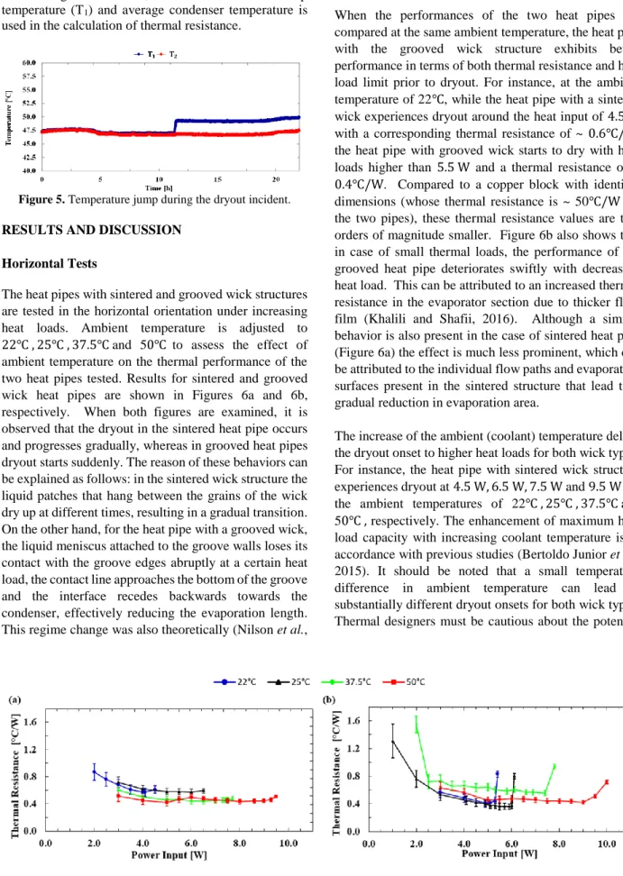
The heat pipes with sintered and grooved wick structures are tested in the horizontal orientation under increasing heat loads. Ambient temperature is adjusted to 22℃ , 25℃ , 37.5℃ and 50℃ to assess the effect of ambient temperature on the thermal performance of the two heat pipes tested. Results for sintered and grooved wick heat pipes are shown in Figures 6a and 6b, respectively. When both figures are examined, it is observed that the dryout in the sintered heat pipe occurs and progresses gradually, whereas in grooved heat pipes dryout starts suddenly. The reason of these behaviors can be explained as follows: in the sintered wick structure the liquid patches that hang between the grains of the wick dry up at different times, resulting in a gradual transition. On the other hand, for the heat pipe with a grooved wick, the liquid meniscus attached to the groove walls loses its contact with the groove edges abruptly at a certain heat load, the contact line approaches the bottom of the groove and the interface recedes backwards towards the condenser, effectively reducing the evaporation length. This regime change was also theoretically (Nilson et al.,
2006) and experimentally (Wong and Chen, 2012) verified in previous studies.
When the performances of the two heat pipes are compared at the same ambient temperature, the heat pipe with the grooved wick structure exhibits better performance in terms of both thermal resistance and heat load limit prior to dryout. For instance, at the ambient temperature of 22℃, while the heat pipe with a sintered wick experiences dryout around the heat input of 4.5 W with a corresponding thermal resistance of ~ 0.6℃/W, the heat pipe with grooved wick starts to dry with heat loads higher than 5.5 W and a thermal resistance of ~ 0.4℃/W. Compared to a copper block with identical dimensions (whose thermal resistance is ~ 50℃/W for the two pipes), these thermal resistance values are two orders of magnitude smaller. Figure 6b also shows that in case of small thermal loads, the performance of the grooved heat pipe deteriorates swiftly with decreasing heat load. This can be attributed to an increased thermal resistance in the evaporator section due to thicker fluid film (Khalili and Shafii, 2016). Although a similar behavior is also present in the case of sintered heat pipe (Figure 6a) the effect is much less prominent, which can be attributed to the individual flow paths and evaporation surfaces present in the sintered structure that lead to a gradual reduction in evaporation area.
The increase of the ambient (coolant) temperature delays the dryout onset to higher heat loads for both wick types. For instance, the heat pipe with sintered wick structure experiences dryout at 4.5 W, 6.5 W, 7.5 W and 9.5 W for the ambient temperatures of 22℃ , 25℃ , 37.5℃ and 50℃ , respectively. The enhancement of maximum heat load capacity with increasing coolant temperature is in accordance with previous studies (Bertoldo Junior et al., 2015). It should be noted that a small temperature difference in ambient temperature can lead to substantially different dryout onsets for both wick types. Thermal designers must be cautious about the potential
Figure 6. Thermal resistance vs. heat load for the (a) sintered wick heat pipe and (b) grooved wick heat pipe at different ambient (coolant) temperatures.
onset of dryout caused by a sudden decrease in ambient temperature.
Although an increase in the ambient temperature causes difficulties in the cooling of devices, enhancing heat pipe performance in response to an ambient temperature increase is a significant reason for the utilization of heat pipes in high temperature environments.
Vertical Tests
Heat pipes with sintered and grooved wick structures are tested at the ambient temperature of 22℃ under increasing heat loads for both gravity resisted and assisted orientations. The resultant thermal resistance variations are shown in Figure 7.
When sintered and grooved heat pipes are positioned against the gravity, dryout phenomenon occurred approximately 1.0 W and 2.0 W earlier than the horizontal tests, respectively. The reason of this performance degradation is the gravitational loss. In horizontal configuration, capillary pressure difference between evaporator and condenser compensates only the pressure drops due to friction generated by the viscous flows of liquid and vapor. In gravity resisted configuration, some part of the capillary head is used to compensate the gravity head, which restricts upper limit of the circulating mass flow rate in the heat pipe. Results also show that grooved wick structure is affected more by the gravitational effect, similar to previous studies (Sauicic et al., 2000; Loh et al., 2005; Russel et al., 2011). When Figure 2 is investigated, it is seen that average hydraulic diameter provided by the grains of sintered wick structure is much smaller than the hydraulic diameter of the grooves. Therefore, capillary force generated by the sintered wick is higher than that of the grooved wick, which leads to a lesser performance loss in gravity resisted operation of the heat pipe with sintered wick.
While the grooved heat pipe is observed to operate at a minimum thermal resistance value of 0.4℃/W in the horizontal position at the onset of dryout, this value is 0.6℃/W in the gravity resisted configuration. On the other hand, thermal resistance values of the heat pipe with sintered wick structure at horizontal and gravity resisted orientations are almost identical, similar to the findings of previous studies (Loh et al., 2005; Russel et
al., 2011). This result promotes the use of a heat pipe with
sintered wicks in applications where it is necessary to operate the heat pipe against gravity. The increase in the thermal resistance observed for the case of lower heat fluxes for the horizontal configuration is also present for the vertical operation.
In gravity assisted experiments, both heat pipes are able to work under higher heat loads without drying when compared to horizontal tests as expected. While the heat pipe with sintered wick exhibits a slight increase in the
heat load limit, the heat pipe with grooved wick shows a performance increase of more than 100% by drying at a power input higher than 12 W. Moreover, the heat pipe with grooved wick has lower thermal resistance, especially near the onset of dryout for gravity assisted condition. For the heat pipe with sintered wick, thermal resistance values are close for both horizontal and gravity assisted configurations. Therefore, heat pipes with grooved wick structures are better alternatives for the application scenarios, where the condenser is positioned at the top (Loh et al., 2005).
Figure 7. Thermal resistance vs. heat loads for the heat pipes with sintered and grooved wicks under gravity assisted and resisted orientations (T∞= 22℃).
When the variation of thermal resistance with heat input is examined in Figure 7, an optimum operating point exists for each case, predominantly for the heat pipe with grooved wick. Optimum point is reached at the onset of the dryout (Alijani et al., 2018). The reason for the efficient operation of the heat pipe at this point is the increase in evaporation efficiency. The thickness of the liquid film at the evaporator attains its minimum value prior to the onset of dryout. In other words, evaporation resistance decreases due to the extremely thin film thickness formed at the micro evaporation region near the groove edges, where a substantial amount of evaporation takes place (Akkuş and Dursunkaya, 2015; 2016; Akkuş
et al., 2017). Although the maximum efficiency is
achieved, the heat pipe operation near the inception of dryout is risky for the grooved heat pipes due to the fact that small fluctuations in the heat load or small variations in ambient temperature can lead to the onset of dryout. In addition, during the experiments it was observed that a heat pipe experiencing dryout cannot immediately achieve the thermal performance prior to dryout, after the heat input is adjusted to lower values. Therefore, heat pipes should not be operated at heat loads in the close vicinity of their dryout limits to eliminate the adverse consequences of dryout.
Uncertainty Analysis
Uncertainty of thermal resistance is based on the uncertainties of heat (power) input estimates and temperature measurements. During the experiments,
power input, 𝑄, to the system was calculated using the current and voltage measurements, i.e. 𝑄 = 𝐼 ∙ 𝑉. Based on the manufacturer’s specification, the uncertainty of the readings was 0.5% of the displayed values on DC power supply device. Following the root of the sum of the squares uncertainty (RSS) approach, the relative uncertainty of heat input,
𝜀
𝑄/𝑄, is calculated as 0.707% using the following formula:(2)
where
𝜀
𝐼 and𝜀
𝑉 are the uncertainties of current and voltage readings. The temperature difference between the evaporator and condenser parts, ∆𝑇, is calculated based on the temperature measurements at the 𝑇𝐶1, 𝑇𝐶3, and 𝑇𝐶4 as given in Equation 1. Therefore, the uncertainty of ∆𝑇 is the function of the uncertainty of these thermocouples as specified in the following formula:(3)
The same type of thermocouples were used at each measurement point and the manufacturer’s uncertainty for these thermocouples is ±0.2℃. Using Equation 3, uncertainty of the temperature difference,
𝜀
∆𝑇, is calculated as ±0.245℃. Finally, uncertainty of the thermal resistance,𝜀
𝑅, is calculated based on the uncertainties of heat input and temperature difference as follows:(4)
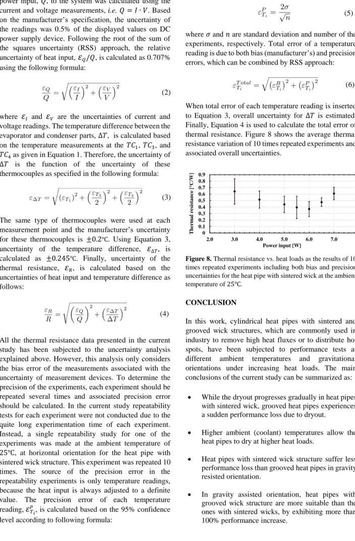
All the thermal resistance data presented in the current study has been subjected to the uncertainty analysis explained above. However, this analysis only considers the bias error of the measurements associated with the uncertainty of measurement devices. To determine the precision of the experiments, each experiment should be repeated several times and associated precision error should be calculated. In the current study repeatability tests for each experiment were not conducted due to the quite long experimentation time of each experiment. Instead, a single repeatability study for one of the experiments was made at the ambient temperature of 25℃, at horizontal orientation for the heat pipe with sintered wick structure. This experiment was repeated 10 times. The source of the precision error in the repeatability experiments is only temperature readings, because the heat input is always adjusted to a definite value. The precision error of each temperature reading,
𝜀
𝑇𝑖𝑃, is calculated based on the 95% confidence level according to following formula:
(5) where 𝜎 and 𝑛 are standard deviation and number of the experiments, respectively. Total error of a temperature reading is due to both bias (manufacturer’s) and precision errors, which can be combined by RSS approach:
(6)
When total error of each temperature reading is inserted to Equation 3, overall uncertainty for ∆𝑇 is estimated. Finally, Equation 4 is used to calculate the total error of thermal resistance. Figure 8 shows the average thermal resistance variation of 10 times repeated experiments and associated overall uncertainties.
Figure 8. Thermal resistance vs. heat loads as the results of 10 times repeated experiments including both bias and precision uncertainties for the heat pipe with sintered wick at the ambient temperature of 25℃.
CONCLUSION
In this work, cylindrical heat pipes with sintered and grooved wick structures, which are commonly used in industry to remove high heat fluxes or to distribute hot spots, have been subjected to performance tests at different ambient temperatures and gravitational orientations under increasing heat loads. The main conclusions of the current study can be summarized as:
While the dryout progresses gradually in heat pipes with sintered wick, grooved heat pipes experiences a sudden performance loss due to dryout.
Higher ambient (coolant) temperatures allow the heat pipes to dry at higher heat loads.
Heat pipes with sintered wick structure suffer less performance loss than grooved heat pipes in gravity resisted orientation.
In gravity assisted orientation, heat pipes with grooved wick structure are more suitable than the ones with sintered wicks, by exhibiting more than 100% performance increase. 2 3 4 5 6 7 8 0 0.1 0.2 0.3 0.4 0.5 0.6 0.7 0.8 0.9 1 0 0.1 0.2 0.3 0.4 0.5 0.6 0.7 0.8 0.9 2.0 3.0 4.0 5.0 6.0 7.0 8.0 Therm a l resistance [ C/W ] Power input [W]
Heat pipes with grooved wick structures operate most efficiently near the onset of their dryout points. Heat pipes experiencing dryout cannot immediately achieve their thermal performance prior to dryout, after the heat input is adjusted to lower values. Heat pipes should not be operated at heat loads very
close to their dryout onsets to eliminate the undesired consequences of dryout.
ACKNOWLEDGEMENT
Authors gratefully acknowledge the support of Serdar Terzi, Mechanical Design Director in ASELSAN-HBT, for the production of the experimental setup. Authors would like to thank Yiğit Karpat and Samad Nadimi Bavil Oliaei for their guidance during the machining of the heat pipes and the process of heat pipe photomicrography. Barbaros Çetin would like to acknowledge funding from the Turkish Academy of Sciences through Outstanding Young Scientist Program (TÜBA-GEBİP) and Science Academy Association Distinguished Young Scientist Award (BAGEP).
REFERENCES
Akkus Y., Nguyen C. T., Celebi A. T. and Beskok A., 2019, A First Look at the Performance of Nano-grooved Heat Pipes, Int. J. Heat Mass Tran.,132, 280-287. Akkuş Y. and Dursunkaya Z., 2015, Investigation of Evaporation Models in the Micro Region of Grooved Heat Pipes and a New Solution Procedure, 20th National
Conference on Thermal Science and Technology (ULIBTK'15), Paper No: 58.
Akkuş Y. and Dursunkaya Z., 2016, A New Approach to Thin Film Evaporation Modeling, Int. J. Heat Mass
Tran., 101, 742-748.
Akkuş Y., Tarman I. H., Çetin B. and Dursunkaya Z., 2017, Two Dimensional Computational Modeling of Thin Film Evaporation. Int. J. Therm. Sci., 121, 237-248. Alijani H., Çetin B., Akkuş Y. and Dursunkaya Z., 2018, Effect of Design and Operating Parameters on the Thermal Performance of Aluminum Flat Grooved Heat Pipes, Appl. Therm. Eng., 132, 174-187.
Alijani H., Çetin B., Akkuş Y. and Dursunkaya Z., 2019, Experimental Thermal Performance Characterization of Flat Grooved Heat Pipes. Heat Transfer Eng., 40, 784-793. Atay A., Sarıarslan B., Kuşçu Y. F., Akkuş Y., Saygan S., Gürer A. T., Çetin B. and Dursunkaya Z., 2017, Experimental Dry Out Characterization of Sintered and Grooved Heat Pipes, 21th National Conference on
Thermal Science and Technology (ULIBTK'17), Paper
No: 182.
Bertoldo Junior J., Vlassov V. V., Genaro G. and Guedes U. T. V., 2015, Dynamic Test Method to Determine the Capillary Limit of Axially Grooved Heat Pipes, Exp.
Therm. Fluid Sci., 60, 290-298.
Faghri A., 1995, Heat Pipe Science and Technology, Global Digital Press.
Gan J. S., Sia T. S., Hung Y. M. and Chin J. K., 2016, Dryout Analysis of Overloaded Microscale Capillary-Driven Two-Phase Heat Transfer Devices, Int. Commun.
Heat Mass, 76, 162-170.
Garimella S. V. and Harirchian T., 2013, Encyclopedia
of Thermal Packaging, Volume 1: Microchannel Heat Sinks for Electronics Cooling, World Scientific.
Harris D. K., Palkar A., Wonacott G., Dean R. and Simionescu F., 2010, An Experimental Investigation in the Performance of Water-Filled Silicon Microheat Pipe Arrays, J. Electron. Packaging, 132, 021005.
Jiang L., Huang Y., Tang Y., Li Y., Zhou W., Jiang L. and Gao J., 2014a, Fabrication and Thermal Performance of Porous Crack Composite Wick Flattened Heat Pipe,
Appl. Therm. Eng., 66, 140-147.
Jiang L., Ling J., Jiang L., Tang Y., Li Y., Zhou W. and Gao J., 2014b, Thermal Performance of a Novel Porous Crack Composite Wick Heat Pipe, Energ. Convers.
Manage., 81, 10-18.
Khalili M. and Shafii M. B., 2016, Experimental and Numerical Investigation of the Thermal Performance of a Novel Sintered-Wick Heat Pipe, Appl. Therm. Eng., 94, 59-75.
Kundu P. K., Mondal S., Chakraborty S. and DasGupta S., 2015, Experimental and Theoretical Evaluation of On-Chip Micro Heat Pipe, Nanosc. Microsc. Therm., 19, 75-93.
Li X., Wang J., Hu Q., Bao L. and Zhang H., 2013, Experimental and Theoretical Research on Capillary Limit of Micro Heat Pipe with Compound Structure of Sintered Wick on Trapezium-Grooved Substrate, Heat
Mass Transfer, 49, 381-389.
Li Y., Li Z., Chen C., Yan Y., Zeng Z. and Li B., 2016, Thermal Responses of Heat Pipes with Different Wick Structures under Variable Centrifugal Accelerations,
Appl. Therm. Eng., 96, 352-363.
Loh C. K., Harris E. and Chou D. J., 2005, Comparative Study of Heat Pipes Performances in Different Orientations, Semiconductor Thermal Measurement and
Management Symposium, 21thAnnual IEEE, 191-195.
Lv L. and Li J., 2017, Managing High Heat Flux Up to 500 W/cm2 through an Ultra-Thin Flat Heat Pipe with
Superhydrophilic Wick, Appl. Therm. Eng., 122, 593-600.
Maydanik Y. F., 2005, Loop Heat Pipes, Appl. Therm.
Eng., 25, 635-657.
Nilson R. H., Tchikanda S. W., Griffiths S. K. and Martinez M. J., 2006, Steady Evaporating Flow in Rectangular Microchannels, Int. J. Heat Mass Tran., 49, 1603–1618.
Peterson G. P., Duncan A. B. and Weichold M. H., 1993, Experimental Investigation of Micro Heat Pipes Fabricated in Silicon Wafers, J. Heat Transf., 115, 751-756.
Peyghambarzadeh S. M., Shahpouri S., Aslanzadeh N. and Rahimnejad M., 2013, Thermal Performance of Different Working Fluids in a Dual Diameter Circular Heat Pipe, Ain Shams Eng. J., 4, 855-861.
Reay D. A., Kew P. A. and McGlen, R. J., 2014, Heat Pipes: Theory, Design and Applications, 6th Edition, Elsevier
Russel M. K., Young C., Cotton J. S. and Ching C. Y., 2011, The Effect of Orientation on U-Shaped Grooved and Sintered Wick Heat Pipes, Appl. Therm. Eng., 31, 69-76. Sauciuc I., Mochizuki M., Mashiko K., Saito Y. and Nguyen T., 2000, The Design and Testing of the Super Fiber Heat Pipes for Electronics Cooling Applications,
Semiconductor Thermal Measurement and Management Symposium, 16th Annual IEEE, 27-32.
Weibel J. A. and Garimella S. V., 2013, Recent Advances in Vapor Chamber Transport Characterization for High-Heat-Flux Applications, in Advances in Heat Transfer, 45, 209-301.
Wong S. C. and Chen C. W., 2012, Visualization and Evaporator Resistance Measurement for a Groove-Wicked Flat-Plate Heat Pipe, Int. J. Heat Mass Tran., 55, 2229-2234.
Atakan ATAY received his BSc. degree from Mechanical Engineering of İ.D. Bilkent University
in 2018. During his undergraduate studies, he took part in Thermal Characterization of
Commercial Sintered and Grooved Heat Pipes and Numerical and Analytical Modelling of Laser and Arc Welding Processes projects, which yielded several conference and journal papers. He
continues his studies in İ.D. Bilkent University as a M.Sc. student. He is currently working on the modeling of motion of Janus particles using Boundary Element Method.
Büşra SARIARSLAN received her B.Sc. degree from Mechanical Engineering of İ.D. Bilkent
University in 2018. During her undergraduate studies, she took part in Thermal Characterization
of Commercial Sintered and Grooved Heat Pipes project. She pursues her M.Sc. degree in İ.D.
Bilkent University since September 2018. She is currently working on microfluidic circulating tumor cell isolation and disease detection kits with PCR. In addition, she carries out her teaching assistance duties.
Yiğit F. KUŞÇU is graduated from İ.D. Bilkent University in 2018, he is currently continuing his
M.Sc. studies at École Polytechnique Fédérale de Lausanne, concentrated on fluid dynamics. Starting from 2016, he has studied thermal modelling of GMAW and laser welding both numerically and analytically, which resulted in several conference papers and funded by TÜBİTAK. Alongside this study, he actively participated the research by experimenting on thermal characterization of industrial heat pipes.
Samet SAYGAN is a senior engineer in ASELSAN Inc. He received his B.Sc. degree from the
Mechanical Engineering Department of Middle East Technical University, Ankara, Turkey, in 2011. He obtained his M.Sc. degree from the Mechanical Engineering Department of Middle East Technical University, Ankara, Turkey, in 2014. He is currently working on his PhD thesis, which is the characterization of flat plate heat pipes, in the Mechanical Engineering Department of Middle East Technical University, Ankara, Turkey. He is responsible for the mechanical and thermal design of electronic devices in ASELSAN Inc. His research focuses on micro-scale two-phase heat transfer devices.
Yiğit AKKUŞ is a senior engineer in ASELSAN A.Ş. He received his B.Sc. and minor degrees
from the Mechanical Engineering and Materials and Metallurgical Engineering Departments of Middle East Technical University, Ankara, Turkey, in 2009, respectively. He obtained his PhD degree from the Mechanical Engineering Department of Middle East Technical University in 2015. He was a post-doctoral fellow in Mechanical Engineering Department of Southern Methodist University, Dallas, U.S.A., in 2017-2018. Dr. Akkuş is responsible for the thermal management and packaging of high heat flux electronics in ASELSAN. His research focuses on macro-, micro- and nano-scale heat transfer, two-phase passive heat spreaders, thin film evaporation and condensation, droplet evaporation, and molecular dynamics simulations. He currently teaches “AAR-652 Passive Heat Exchange Devices and Phase Change” course in ASELSAN Academy.
A. Türker GÜRER is the manager of Mechanical Design Department in Communication and
Information Technologies Business Sector of ASELSAN Inc. He obtained his B.Sc., M.Sc. and PhD degrees from the Mechanical Engineering Department of Middle East Technical University in 1994, 1997, and 2003, respectively. In his department, Dr. Gürer supervises various groups which are responsible in mechanical, structural and thermal design of communication devices, stabilized antenna systems, and integration of these systems onto military platforms.
Barbaros ÇETİN is an associate professor in the Mechanical Engineering Department at İ.D.
Bilkent University, Ankara, Turkey. He received his B.Sc. (2002) and M.Sc. (2005) in Mechanical Engineering at Middle East Technical University, Ankara, Turkey, and his PhD (2009) in the Department of Mechanical Engineering at Vanderbilt University where he focused on electrokinetic transport and particle manipulation in lab-on-a-chip devices for biomedical applications. Following his PhD, he became a faculty member in Middle East Technical University-Northern Cyprus Campus Mechanical Engineering Program. In 2011, he joined İ.D. Bilkent University. His current research interests include microfluidic bioparticle manipulation, modeling of particle motion using boundary element method, and modeling, fabrication, and experimentation of flat-grooved heat pipes. Dr. Çetin is the recipient of the 2015 İ.D. Bilkent University Distinguished Teacher Award, 2017 Outstanding Young Scientist Award of the Turkish Academy of Sciences (TÜBA-GEBİP), 2017 METU Prof. Dr. Mustafa N. Parlar Research Incentive Award and 2018 Science Academy Association Distinguished Young Scientist Award (BAGEP).
Zafer DURSUNKAYA is a professor at the Mechanical Engineering Department of Middle East
Technical University, Ankara, Turkey, where he obtained his B.Sc. in 1981. He received his M.Sc. and Ph.D. degrees from the Mechanical Engineering Department of Illinois Institute of Technology, USA, in 1984 and 1988, respectively. Prior to joining Middle East Technical University, he worked in Ricardo between 1989 and 1994 as a senior engineer. His research interests include micro-grooved heat pipes, moving boundary/phase change problems, piston lubrication and its design, oil consumption in internal combustion engines, hydrodynamic lubrication, journal bearings, piston ring dynamics, and ring lubrication.