2019
Double Stud Cargo Fitting Research, Alternative Cargo Clip Design
Double Stud Cargo Fitting Research, Alternative Cargo Clip Design
and Analysis
and Analysis
Cemal İrfan Çalişkan
Fatih Sultan Mehmet Vakif University,Aluteam, [email protected]
Ebubekir Koç Dr
Fatih Sultan Mehmet Vakif University,Aluteam, [email protected]
Hamaid Mahmood Khan Dr
Fatih Sultan Mehmet Vakif University,Aluteam, [email protected]
Mustafa Enes Bulduk
Fatih Sultan Mehmet Vakif University, Aluteam, [email protected]
Follow this and additional works at: https://commons.erau.edu/ijaaa
Part of the Aerospace Engineering Commons, and the Aviation Commons
Scholarly Commons Citation Scholarly Commons Citation
Çalişkan, C., Koç, E., Khan, H., & Bulduk, M. (2019). Double Stud Cargo Fitting Research, Alternative Cargo Clip Design and Analysis. International Journal of Aviation, Aeronautics, and Aerospace, 6(5).
Introduction
In air transportation, fixing the cargo inside the aircraft is important in terms of both flight safety and operational process. Positioning and fixing of the cargo to the aircraft within a short period of time without any risk in terms of flight safety is carried out with the use of some apparatus and subsystems within the pre-determined rules. This fixation is carried out by covering the cargo loaded onto aluminium pallets. The connection of the net on the pallet is provided by metal apparatuses known as clip (Figure 1). These apparatuses are also referred to in the aerospace industry as cargo fitting, double stud cargo fitting. In this study, the design development process of these clips in the history of aviation design, the alternative clip design work we have done and the comparative analysis of this design will be discussed. Firstly, we will address our work on cargo clip in parallel with the historical development process. In this context, different systems and apparatus design studies from the 1950s until the present day will be examined in order to load and stabilize the cargo. In our review, the design development process of cargo clip, the formation of the standard product, with the patent images of the period will be detailed. In this patent review, cargo loading system designs for cargo aircraft and apparatus patent applications designed for cargo operations were utilized.
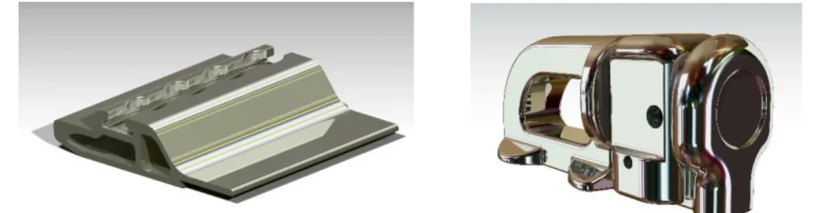
Figure 1. Cargo pallet profile with clip fastening used today (on the left). The
standard double stud cargo fitting (clip) product currently in use (on the right).
Cargo Clip Historical Review
50 years in which the building blocks of commercial aviation began to form, brought with them many problems that need to be solved. One of these problems is the loading of the cargo into the aircraft and the fixation of the loaded cargo. In our research on these subjects, more commercial products and patent applications belonging to these products were found. These data were used in the formation of the literature content. The clip design development process, which we discuss in parallel with the history of commercial cargo transportation, will be dealt with by the need for the relevant field, the ideas produced for the subjects needed, and the formation of standard products. In the historical review of the cargo clip, the use of jet-engine aircraft in commercial transportation was the starting point.
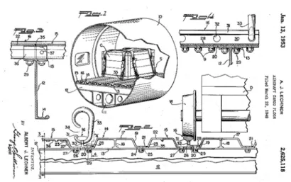
Airlines (Lamiman, 2011). In Europe, we can say that similar developments started to take shape on 18 December 1970 after the Airbus program was formed in 1965 (Simons, 2014). In this context, it can be stated that cargo loading systems and apparatus started to appear as a need in the 1950s. It will be correct to examine the process through period patents. We can say that the oldest patent that we can find on air cargo loading systems is the design of January 1953(Lechner, 1953). In the aircraft floor design of Albert J. Lechner, the cargo is transported into the aircraft with the train rails-like transmission element. The fixing of the cargo shipped on the rails on the floor is provided by straps connected to the hook-like metal between the rails on the ground (Figure 2). In Figure 2, it is possible to express this hook represented by no. 33 as the clip of the period. It is seen that the clip mechanism designed for cargo fixing is shaped as a hook in this design. Cargo is fixed to the hook on the floor by means of belts by taking the miniature sized cargo wagon into the plane over the rails. There are no floor rails and freight wagons in this design in modern era aircraft. In the design, it is clear that the cargo loading application in railway transportation is designed for cargo planes.
Figure 2. Albert J. Techner's 1953 dated aircraft floor design patent (Lechner,
1953).
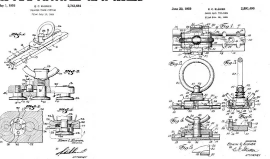
In today's cargo shipments, it is stated that the use of the clip-fixing technique is used to wrap the pallets with the net. The standard clip design, which is the subject of our research, was first encountered in the late 1990s. However, the idea of securing the clip to the standard profile channel is first seen in the 1956 patent (Figure 3). Although today's cargo pallet profiles differ in general from these images, the holes and the channel just below it are used in today's systems. In addition, the principle of creating a suitable space for the locking mechanism of the empty structure still used today is clearly described in the design images (Elsner, 1956). In Elsner's two patents in 1956 and 1959, the system is the same, but the design differs in the profiles produced by the
extrusion method and in the hole forms where the mechanism is locked (Figure 3). It can be said that the mechanism is similar to today's standard clips in terms of general working principle.
Figure 3. Edwin C. Elsner's 1956 (Elsner, 1956) and 1959 patents (Mar,
1959).
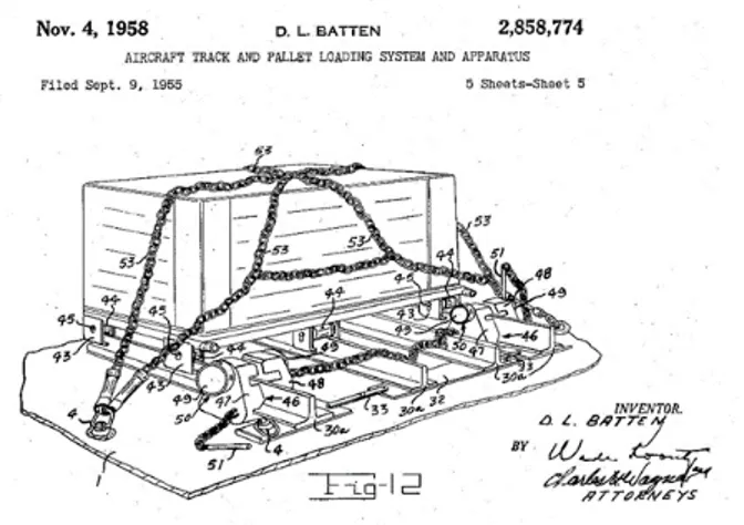
In the following years, we see that the train rail form is preserved in the design ideas for the in-flight cargo loading. In the patent registered in the name of Dallas Lee Batten in 1958, the rails placed on the ground, the wheeled vehicle mounted on these rails and the task of the stopper are designed in a functionality resembling the railway infrastructure (Figure 4). In this design similar to the rail style, the pallet is fixed with the chain and the hook mounted on the floor (part 4) is used in the clip function in the design (Lee, 1958). The design in question was similar to the design of Lechner in 1953 and was inspired by railway transportation. We think that the cargo designs with railroad inspiration, which we share details between 1953-1959, are commonplace due to the technology of the era.
Figure 4. Patent of aircraft floor and pallet loading system and apparatus
design registered in 1958 on behalf of Dallas Lee Batten (Lee, 1958).
The current cargo clip design, which is the subject of our research, is the model of the clip model which is used in the 1990s. However, in this development process, some different design ideas can be mentioned between the wagon and the loading procedure and the use of the current clips, the cargo methods and the fixing of the cargo. We would like to consider these examples in the context of fixing the cargo, which is the application area of the clips. Michael Cozzoli's 1962 design patent, while moving on rails, also hangs on the system at the top (Cozzoli, 1962). In this highly complex system, the fixing of the cargo is provided by a mechanical system. This system is very complex and has difficulties in operational terms considering the condition of the cargo carried by the pallet with the clip in the following periods (Figure 5).
Figure 5. 1962 registered cargo system and an apparatus design patent on
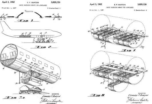
In Edward F. Burton's patent of 1962, the cargo containers were designed in the form suitable for the aircraft body. In this system, the loading and unloading of the cargo fixed to the aircraft body from the upper section are provided by a crane-like system with the hanging of the ropes. (Figure 6). In this system, the containers moving on the rail in the upper part are fixed mechanically (Burton, 1962). It is noteworthy that the last two patents of 1962 were quite complex within the systems implemented. However, we wanted to give place to our study in terms of the different approach they brought to the solution of the problem. Furthermore, the similarity of the container form in the design of Edward F. Burton to the current containers compatible with the aircraft body is also important.
Figure 6. The patent for cargo loading systems, registered to Edward F.
Burton, dated 1962 (Burton, 1962).
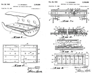
When we come to 1963, we find floor design that resembles Thorvald K. Petersen's modern-day planes, but with simpler details (Petersen, 1963). Petersen’s design utilized balls that act as airbags instead of ground rails in previous designs (Figure 7). In our research on design patents in aviation, we found this study as the first example close to today's cargo floor application. The cargo loaded into the aircraft by the vehicle is taken to the appropriate area, manually, on the ground. This example is noteworthy in terms of its proximity to today's application, as well as the necessity of using flat pallets at the bottom of the aircraft. However, this design does not include any details on the cargo clip.
On the use of the cargo clip in the present day, in the examinations, we carried out in Turkish Airlines Cargo facilities, some information about the application practices and rules were obtained. In the field application, the manually-moved cargo on the balls is on a pallet and wrapped with the net to secure the cargo. In this application, clips are used for fixing the net. Each oversized pallet net is secured with 18 clips. The Petersen design of 1963, which we found as the first example of a manual movable floor design of the pallet, contributed to the process with this feature.
Figure 7. T.K. Petersen's 1963 dated air cushion floor design patent (Petersen,
1963).
The clip style, which started in 1956, has developed in similar forms in general to the present. The patent of Bass and Warren, dated 1967, consists of the interpretation of the similar form. While the fixing of the clip, designed as interlaced on the standardized extruded profile in different forms from today's profile, differs from the standard products, the working principle is exactly the same.
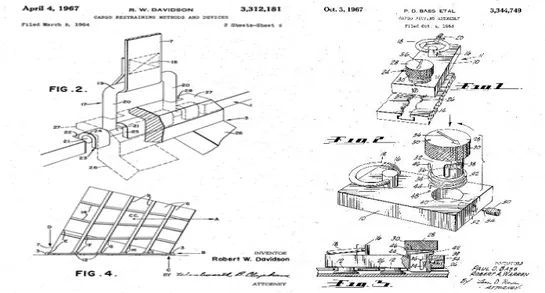
However, there are also designs that bring different interpretations to the subject during the period. One of them is the clip dated 1967 by Davidson which named Cargo Restraining and Devices (Figure 8). A belt buckle-like metal is used which is similar to the standard clip mechanism in the design developed to dampen the movement of the cargo more in the vehicle (Davidson, 1967). Although this design offers a different approach according to the standard design, we believe that it does not provide an operational advantage. We can say that this application was not encountered in our field studies.
Figure 8. Robert W. Davidson's 1967 patent clip (on the left) (Davidson,
1967). Paul D. Bass and Robert A. Warren's 1967 patent clip image (on the right) (Bass & Warren, 1967).
The 1970s is the period when significant developments in aviation were achieved. At the end of the 1960s, the Boeing 727 and 737 models were being flown by airline companies. In 1970, the Boeing 747s, which had a capacity of 450 passengers, was introduced to the service (Lamiman, 2011). The Eastern Airlines A300 order which includes 23 airplanes, in the year 1978, is an example of developments in the European aviation industry (Simons, 2014). With the launch of these aircraft models which still using today, it can be seen that the design registration applications on the ground floor and cargo apparatuses made in the same period are not coincidental. In the patent applications made in the 1970s, we can say that the air cargo loading equipment and vehicles used today are frequently encountered. In post-1970 applications, the issue of how the cargo will be loaded onto the plane is now evident. The rails that extend to the aircraft or the suspension, mechanisms for carrying the load in the suspension, and the stopper mechanisms in the complex structures are now behind. It is clear that the cargo will be placed in the plane by moving the cargo on the floor in a container or a pallet. The fact that the cargo transport application on the pallet is standard has brought about the necessity to standardize the clip application mounted on the standard profile.
Patents of 1956 and 1959 were mentioned about clip-on clips that provide locking on the profile. The design of Bass and Warren, which has the similar working principle in 1967, is remarkable (Figure 8). It can be stated that the general form properties of the design which has a similar application with the present-day clip are generally more angular and have a mechanism designed for function (Bass & Warren, 1967).
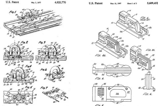
The final design patent application we encountered before today's clip is Richard E. Mclennan and Robert Looker's 1978 clip design (Figure 9). In this product, the mechanism fitted on the standard profile can also be fixed with a spring catch. The profile seen in the design attracts attention with its similarity to today's cargo pallets. When we look at the world commercial aviation, the fact that the stones begin to sit in place shows that some standards are beginning to emerge. In our research, we can say that Edwin C. Elsner's design in 1956 pioneered the general system on the general working principle of the clip mechanism. It can be stated that the system is approaching the present day with its 1977 design. The products developed after this date can be defined as different forms of today's clip. The fact that a significant portion of the next period clip patent applications belongs to Richard E. Mclennan and Robert Looker (McLennan & Looker, 1978) shows us the importance of the pair in turning the clip product into an industrial product.
Figure 9. 1977 Richard E. Mclennan and Robert Looker design patent (on the
left). Patent of the same names 1997 (on the right) (Wagner et al., 1997).
Alternative Design Process
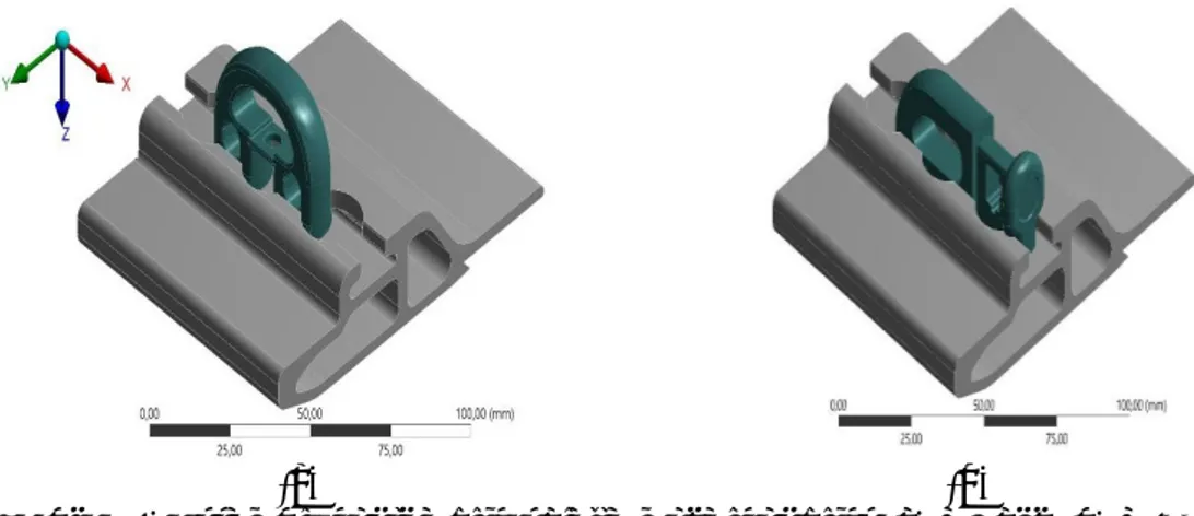
In this part of our study, V2 and V3 models which we have designed as an alternative to the standard cargo clasps product will be mentioned. The cargo clip alternative design is made in Catia V5. Modelling work consists of a total of 5 bodies; the main body, handle, spring, brake mechanism, and mounting nut (Figure 14). Part design tools were used in modelling.
In the alternative design process, standard clip modelling is first defined by V1 (Figure 1). Classical product modelling will be used for
comparison purposes in analysis studies. In V1 modelling, a reverse engineering study was carried out with reference to standard product dimensions and design details. Then V2 alternative design will be modelled (Figure 10).
Figure10. V2 alternative design.
With the result of V2 design work, the data recorded in STL format is produced by SLS (Selective Laser Sintering) from the PA 2200 Polyamide material (Figure 11).
Figure11. SLS production prototypes of V2 alternative design. Function test
on the palette on the left. Connection test of cargo net on the right.
In the prototype trial, the function of the clip on the profile and cargo net is applied. The clip, the mechanism of the spring mechanism on the profile, does not experience any difficulties. However, in the case of the cargo net clip application, the net rope prevents the operation of the mechanism. In addition, it was evaluated that mechanism holding form is not suitable for operational process and it would be difficult to grasp mechanism with a glove. After the evaluations made on V2 design, it is decided to design the V3 model (Figure 12). In the V3 design, the upper part of the cargo net is enlarged; the retention form is extended downward to make it more functional. After design modelling, SLS prototype production and function tests are performed.
Figure12. V3 alternative design. Revision form on the right (2018 07647,
2019).
In prototype production, it was determined that the cargo network does not interfere with the operation of the mechanism as in V2 (Figure 13). In addition, the expected reduction in clip design is also provided. The weight of the standard clip made of automaton steel is 0.106 kg; 13.25% reduction was achieved in the first stage in the V3 design to be produced from the same material.
Considering the use of 18 clips in a cargo pallet, this lightening of the weight of hundreds of clips on the cargo plane will be effective in fuel savings.
Figure13. V3 alternative design pallet assembly image (on the left). Function
tests after SLS prototype production (on the right).
As seen in Figure 14, in the standard clip design, the second of the legs that the connection with the profile is provided is not in full cylindrical form due to the section allocated to the spring mechanism (Figure 14, classic design part 1). In the design of V3, a solution must first be made to this problem. For this reason, a symmetrical model was preferred in the design, with both feet cylindrical. The clip on the profile has 2 full feet and thus provides a stronger grip.
Figure14. V3 alternative design technical details (on the left) (2018 07647,
2019). Classic design (on the right). Foot (nr.1), mechanism lock handle (nr.2), spring (nr.3), lock (nr.4).
The standard clip is an asymmetrical design. In our applications, the clip has difficulty in attaching the clip to the profile as the locking mechanism is not in the centre. We believe that the application will be more comfortable in a symmetrical model. In this case, a balanced distribution of the load on the clip will also be ensured. For this reason, in the v3 design, the locking mechanism is taken in the middle section and space is recovered.
Design Analysis
This section deals with the mathematical evaluation of the mechanical properties of the proposed clips (V1 and V3) - palette assembly using finite element tool (ANSYS). At first, the assembly was modified to include the most stressed region so as to mesh it with sufficient grid density in order to simulate it on a standard work-station. Later, the model was used to the evaluate equivalent stress, strain and total deformation near the contact region and also to measure the maximum loading capability of an assembly with different clips.
An implicit finite element model was, therefore, proposed to simulate the quasi-static loading effect on the 3D geometry of a clip – palette assembly for handling the maximum loadings in the airline baggage system. The equivalent stress distribution, total deformation, equivalent strain and maximum loading capability of an assembly were numerically evaluated at the feet of the clip-palette assembly for both standards and proposed models to confirm the design objectives.
The 3D CAD model of a clip-palette assembly with both version of clips, V1 and V3 are shown in Figure 15.
(a) (b)
Figure 15. Assembly for the clip-palette model for clips (a) V3 and (b) V1.
The clip-palette interaction was modelled as a flexible assembly with palette being fixed at the bottom. The clip on the palette was constrained in only one direction i.e. along the Y-axis with a very little movement along the Z-axis to facilitate its easy movement within the palette along the X-axis. Since palette is an expensive part of the clip-palette assembly, therefore, it was imperative to minimize the palette deformation during the introducing, lifting, shifting and removing of the loads. Thus, the clips were supposed to take the maximum deflection to prevent the costly replacement of the palettes.
To evaluate the stress distribution in the model due to the applied load, the elastic FEA model is employed to resolve the problem both economically and scientifically. The stress is related to the strain by (ANSYS Inc., 2010);
{𝜎𝜎} = {𝐷𝐷}{𝜀𝜀} 1)
Where, 𝜎𝜎, 𝐷𝐷 𝑎𝑎𝑎𝑎𝑎𝑎 𝜀𝜀 are the stress vector, elasticity or elastic stiffness matrix and the elastic strain vector respectively. Here, the elastic strain vector is equal to total strain vector in absence of thermal strain. The total strain vector can be re-written or inverted as;
{𝜀𝜀} = {𝐷𝐷−1}{𝜎𝜎}
2) The above relation can be written in a simplified form using cartesian space coordinates as shown below. For an isotropic material, strains are given as; 𝜀𝜀𝑥𝑥𝑥𝑥 = �𝜎𝜎𝑥𝑥𝑥𝑥× 𝜈𝜈(𝜎𝜎𝑦𝑦𝑦𝑦+ 𝜎𝜎𝑧𝑧𝑧𝑧)� 𝜀𝜀𝑦𝑦𝑦𝑦 = �𝜎𝜎𝑦𝑦𝑦𝑦× 𝜈𝜈(𝜎𝜎𝑧𝑧𝑧𝑧+ 𝜎𝜎𝑥𝑥𝑥𝑥)� 𝜀𝜀𝑧𝑧𝑧𝑧 = �𝜎𝜎𝑧𝑧𝑧𝑧× 𝜈𝜈(𝜎𝜎𝑥𝑥𝑥𝑥+ 𝜎𝜎𝑦𝑦𝑦𝑦)� 𝜀𝜀𝑥𝑥𝑦𝑦= 1+𝜈𝜈𝐸𝐸 𝜎𝜎𝑥𝑥𝑦𝑦, 𝜀𝜀𝑦𝑦𝑧𝑧 =1+𝜈𝜈𝐸𝐸 𝜎𝜎𝑦𝑦𝑧𝑧 and 𝜀𝜀𝑧𝑧𝑥𝑥 =1+𝜈𝜈𝐸𝐸 𝜎𝜎𝑧𝑧𝑥𝑥 3) Where 𝐸𝐸 and 𝜈𝜈 are the elastic modulus and the Poisson’s ratio of the materials.
𝜎𝜎𝑒𝑒𝑒𝑒𝑒𝑒 = �𝜎𝜎12 + 𝜎𝜎22 + 𝜎𝜎32+ 2𝜈𝜈(𝜎𝜎1𝜎𝜎2+ 𝜎𝜎2𝜎𝜎3+ 𝜎𝜎3𝜎𝜎1) 4) Where, 𝜎𝜎1, 𝜎𝜎2, 𝑎𝑎𝑎𝑎𝑎𝑎 𝜎𝜎3 are the three principal stresses. The equivalent or VonMises stress can be computed as;
𝜎𝜎𝑒𝑒𝑒𝑒𝑒𝑒 = �12[(𝜎𝜎1× 𝜎𝜎2)2+ (𝜎𝜎2× 𝜎𝜎3)2+ (𝜎𝜎3× 𝜎𝜎1)2] 5) And finally, the equivalent stress - strain relationship is defined by;
𝜎𝜎𝑒𝑒𝑒𝑒𝑒𝑒 = 𝐸𝐸𝜀𝜀𝑒𝑒𝑒𝑒𝑒𝑒 6)
Meshing
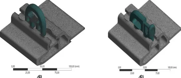
A tetrahedral unstructured mesh with about 3.5 million elements was applied for the clip–palette assembly as shown in Figure 16.
(a) (b)
Figure 16. Complete mesh profile of clip - palette assembly for clips (a) V3
and (b) V1.
The mesh was iteratively adapted to refine the projected regions and a stress gradient within 10% of the maximum value observed until grid independence was achieved. For a complex geometry like this, the tetrahedral elements were found to give a better performance and solution close to experimental. The problem was therefore not found sensitive to grid density when the sufficiently large number of elements were applied in the model. For greater control over sizing, proximity and curvature were adopted along with a slow transition rate, fine span angle and element growth rate at 1.2. Furthermore, at the contact regions of the clips and the palette, the feet and the projected overhang were further refined with small face sizing of 0.5 to capture the various effects closely.
the X-axis and the results were found unaffected due to the localized stress effect at the contact regions. Moreover, the loading was ramped from zero to maximum on the top of the clip to evaluate the critical stress in an assembly for design constraints. A gap of 0.9mm between the clip feet and the base of the palette was modelled to establish a bonded contact behaviour at the onset of the loading. The fixing of the palette was also extended to the entire base to address the deflections and stress distributions in the thin walls of the palette but as the stresses were highly localized near the contact region, the effect of loading was found insignificant outside of it.
Citing the localized effect of the loading on the stress distribution (Jared et al., 2017), the assembly was, therefore, modified to principally focus on the contact region of the clip–palette assembly and to conserve the computational efforts since in the given model, the number of elements reached too high to be able to simulate on a standard work-station. Therefore, the model of Figure 1 was re-defined in Figure 17 without much of the blue zone to include only the contact area and the clip was included without its locking mechanism. This effort reduces the mesh size to about 1.5 - 1.6 million elements for the two assemblies and the solution was found relatively unchanged with this modification. In the finite element model, large strain deformation was also included as the assembly was observed to experience a significantly high displacement.
(a) (b)
Figure 17. Mesh profile of a modified assembly for the clip-palette assembly
for clips (a) V3 and (b) V1.
An important point regarding the constraints of V1 clips is made here. Due to the design methodology adopted in V1 clips, the position of the foot of the clip viz-a-viz the foot of the palette was found different during the loading of the palette and the variation was recorded within a range of 2 mm as shown in Figure 18. This results in instability in the clip–palette arrangement. Conversely, this movement was nearly absent in the V3 clip due to its symmetrical geometry and centrally loaded locking mechanism.
(a) (b)
(c)
Figure 18. Schematic representation of clip – palette feet arrangement for clip
V1 at its (a) front, (b) middle, and (c) back position with respect to the palette. The total overlapping of clip (V1) foot under the palette foot can be seen in Figure 4(a) whereas insufficient overlap in the other two cases i.e. middle and back are shown in Figure 4(b) and (c). The difference in the overlapping of the feet is supposed to provide imbalance to the assembly which can translate into different stress and strain in the structure. Therefore, three different assemblies with V1 clips were considered based on their positions for numerical evaluations. While material Al7075 was fixed for the palette, the simulation with clips was tested with two different materials i.e. automatic steel and maraging steel (MS1). For complete stress analysis, Table 1, lists down the required structural material properties for 3 different materials.
Table 1
Mechanical Properties
Properties Automatic Steel Al7075 Maraging steel (MS1) Units
Density 7800 2823.4 8050 Kg/m3 Young’s Modulus 210 71 150 GPa Poisson’s Ratio 0.28 0.33 0.33 Yield strength 490 503 1100 MPa Ultimate strength 700 572 1200 MPa
For simulation, a single force was chosen for analysis to identify the difference in performance between the two designs. The three different positions of the old clip model were also incorporated in the study and the obtained results are shown in Table 2 and 3.
Table 2
Deformation, Strain, Stress at 1500 N for Clips with Automatic Steel (AS)
Assembly Deformation
(mm) Strain (mm/mm) Stress (MPa) LoadinMax m g (N)
Clips Profile Clips Profile Clips Profile V3 New 0.0093 5 0.00796 0.00103 0.00154 146.9 96.4 5003,7 V1 Front 0.0104 3 0.00991 0.00148 0.00198 222.8 118.0 3299,5 V1 Middle 0.0102 0 0.00968 0.00185 0.00192 312.3 110.7 2353,5 V1 Back 0.0103 0 0.00975 0.00223 0.00159 351.1 104.3 2093,7
Table 3
Deformation, Strain, Stress at 1500 N for Clips with Maraging Steel (MS1)
Assembly Deformation (mm) Strain (mm/mm) Stress (MPa) Max m Loading
(N)
Clips Profile Clips Profile Clips Profile
V3 New 0.01108 0.00869 0.00135 0.00185 148.1 115.7 6518,9 V1 Front 0.01213 0.01080 0.00229 0.00224 235.7 130.7 5770,9 V1 Middle 0.01183 0.01060 0.00279 0.00214 326.3 121.2 5056,8 V1 Back 0.01196 0.01061 0.00335 0.00181 366.3 115.8 4504,6 The maximum permissible loading is attributed to the minimum yield strength of a component in a given assembly (Kawamura, Hayashi, Inoue, & Masumoto, 2001). In assemblies with automatic steel (AS), the clip yielded before the palette owing to its lower yield strength, whereas, in case of assemblies with MS1 material with high yield strength, the mixed behaviour was observed where at lower stresses in the clip, palette was found yielding before the clip and at higher stresses, the clip yielded before the palette. Table 2 and Table 3 also include the maximum loading capacity of the different assemblies which were re-examined using the parametric tool within Workbench (Ansys Inc., 2009).
As seen in Table 2 and Table 3, between the clip and the palette, the stress and strain formation and the total deformation were observed more in the clips than the palette due to the direct application of the force in it through the holder. And between the materials, as the yield stress of the automatic steel was half to that of MS1, the maximum loading capacity of the palette with MS1 clips was, therefore, found comparatively higher than AS clips irrespective of the clip model. The simulated results of the clip–palette assembly for the middle state of clip V1 and new design V3 are shown in Figure 5 for reference. The effect of the material on stress & strain formation and the total deformation was also observed lower in assembly with AS clips for all the cases. However, the difference was seen insignificant in the new design between the two materials. See Figure 19.
(a)
(b)
Figure 19. Simulation results of equivalent stress for (a) new design with V3
clips and (b) old design with middle position of V1 clip.
Between the design of the clips, the new version V3 was found to withstand loading more than the version V1 for all the cases examined. A significant difference in stresses can be seen in assemblies with V3 clips compared to the old design (V1) both in the clip and palette structures. The difference was found more noticeable between the clips due to the direct application of the load. The introducing of stresses in the palette was also found lower with V3 clips that agrees well with the design objective. The strain formation and the total deformation in assembly with V3 clips were also seen comparatively lower than assembly with V1 clips.
Within the old design, the front state of the V1 clip–palette assembly displayed the least stress in the clip which, however, introduces comparatively higher stresses in the palette profile. On the other hand, the equivalent strain and the total deformation were found relatively similar among the different positions of V1 clip–palette assembly. Where the front state among the V1 clip–palette assembly due to the total overlapping of the feet results in highest loading capabilities but the high fickleness in V1 clip’s position leave it highly unlikely to retain its front state at all time. Although, the front position is more likely to occur as its centre of mass is more towards the front of the clip but given the size of the palette, loading anywhere can give rise to other possible positions for clips – palette arrangement. Therefore, considering the 18 clips in a single palette, an average loading for V1 clip can result in a significant difference in maximum loading from V3 clips. This puts the new design in a much better position comprising the stress and strain and loading parameters.
Moreover, on repeated clip – palette fitment trial, clip V3 was also found smoother in operation and less stressful to the assembly as a whole.
Finally, stressing the design objective to achieve nominal stresses in an expensive palette profile, clip V3 was found to fit the purpose. And the maraging steel owing to its higher mechanical properties can provide better loading capabilities at the cost of marginally higher deformation and stress and strain development than the automatic steel. Moreover, the total cost saving using new design (V3 clips) for all the manufactured clips is noteworthy to
mention here. V3 clips were found to occupy 2.46 cm3 less volume than V1
clips that translate into saving of nearly 19g of weight per clip which is substantial when all the clips in an airline industry are considered.
Conclusion
Over the past years, air transportation grows 5%, 6% annually. It is obvious that the annual increase in air transport means more fossil fuel consumption. We think that any solution that will reduce the use of fuel in air transportation is important for our future. The positive impact of the new clip design approach in our cargo products on fuel saving will give us satisfaction.
References
ANSYS, Inc. (2009). Workbench A. Retrieved from
http://research.me.udel.edu/~lwang/teaching/MEx81/ansys56manual.p df
ANSYS, Inc. (2010). Mechanical applications theory reference. Retrieved from http://dl.mycivil.ir/reza/ans_thry.pdf
Bass, P. D., & Warren, R. A. (1967, October 3). Cargo fitting assembly. Google Patents.
Burton, E. F. (1962, April 3). Cargo handling means for airplanes. Google Patents.
C.İrfan Çalışkan, Fatih Sultan Mehmet, & Vakıf Üniversitesi. (2017). Uçak
kabin içi inovatif ürünler ve eklemeli imalat ile üretimi.
Çaliskan, C. İ. (2019). 2018 07647. Turkey: Turk patent Enstitusu.
Davidson, R. W. (1967, April 4). Cargo restraining methods and devices. Google Patents.
Elsner, E. C. (1956, May 1). Tie-down track fitting. Google Patents.
Jared, B. H., Aguilo, M. A., Beghini, L. L., Boyce, B. L., Clark, B. W., Cook, A., … Robbins, J. (2017). Additive manufacturing: Toward holistic design. Scripta Materialia, 135, 141–147.
https://doi.org/10.1016/j.scriptamat.2017.02.029
Kawamura, Y., Hayashi, K., Inoue, A., & Masumoto, T. (2001). Rapidly solidified powder metallurgy Mg97Zn1Y2Alloys with excellent tensile yield strength above 600 MPa. Materials Transactions, 42(7), 1172– 1176.
Lamiman, K. (2011). The Boeing Company. Better Investing, 60(9), 25–26. https://doi.org/D6-27370-TBC
Lechner, A. J. (1953, January 13). Aircraft cargo floor. Google Patents. Lee, B. D. (1958, November 4). Aircraft track and pallet loading system and
apparatus. Google Patents.
Mar, P. (1959). United States patent office.
McLennan, R. E., & Looker, R. (1978, April 25). Quick disconnect tie-down
anchor. Google Patents.
Michael, C. (1962, October 23). Cargo-handling system. Google Patents. Petersen, T. K. (1963, October 29). Sectional air cushion cargo floor.
Retrieved from https://patents.google.com/patent/US3108698A/en Simons, G. (2014). The Airbus A380: A history. South Yorkshire, England:
Pen & Sword Books, Limited.
Wagner, U., Limburgerhof, H. J., Henrici, K., Kuessner, H. , Volkamer, K., & Fuerst, E. (1997). United States Patent (19). BASF Aktiengesellschaft, (19).