97 RESEARCH ARTICLE / ARAŞTIRMA MAKALESİ
ADAPTIVE VIDEO TRANSMISSION OVER COMMUNICATION NETWORKS
Ersin GÖSE1*
1National Defence University, Istanbul *Corresponding Author
[email protected] ORCID No: 0000-0001-8428-2380 Osman Nuri UÇAN2
2Altınbaş University, School of Engineering and Naturel Sciences, Department of Electrical and Electronics Engineering, Istanbul [email protected] ORCID No: 0000-0001-8428-2380
Ghaidq Nassr NAFEA3
3Altınbaş University, School of Engineering and Naturel Sciences, Department of Electrical and Electronics Engineering, Istanbul [email protected] ORCID No: 0000-0002-8987-5529
Oğuz BAYAT4
4Altınbaş University, School of Engineering and Naturel Sciences, Department of Software Engineering, Istanbul
[email protected] ORCID No: 0000-0001-8428-2380
Received Date/Geliş Tarihi: 04/12/2018 Accepted Date/Kabul Tarihi: 17/07/2019 Abstract
This paper is to minimize video bitrate and keeping the high resolution video file manageable. This process is achieved by using new generation of Advanced Video Coders (AVC). Such process can be done at one level encoder or multi levels of encoders by means of transcoding, where reformatting the content to be streamed on channel is called transcoding. The goal is concerned of encoder processes that can be used to achieve transcoding. The codec used for compression of video is H.264, a standard for providing high definition video at substantially low complicity and lower bit rates. The x264 Library is used for encoding H.264 AVC, undergirds some of the most profiles for broadcasting and streaming operations over wired and wireless channels, including different applications. When a technique of bit-rate control is incorporated with the encoder, more reliable and qualified system for low bitrate video streaming over constant bit rate communication channel is achieved, where output rate of the video encoder is controlled by feedback based on the buffer level. Where the most effective parameters such as skip frame, QP, cycle length (Gop), etc. are configured and it used as a rate control tools to test the streaming coded bit rate and the decoded video quality. Testing scenarios use many different videos with QCIF, CIF, and HD formats encoded under main profile. JM19 reference software is used for implementing and testing the standards.
98
İLETİŞİM AĞLARI ÜZERİNDEN UYARLANABİLİR VİDEO İLETİMİ Öz
Bu makalenin amacı video bithızını düşürme ve yüksek çözünürlüklü video dosyasının boyutunu uygun halde tutabilmektir. Bu işlem yeni nesil bir İleri Video Kodlayıcı ile yapılır. Bu tür bir işlem, tek düzeyli ya da çok düzeyli kodlayıcılarla yapılabilir. Amaç, kod çevrimine ulaşılabilecek bir sürecin yürütülmesidir. Video sıkıştırması için kullanılan kod çözücü H.264’tür. H.264 AVC’nin kodlanması için x264 kütüphanesi kullanılmıştır. Bithızı kontrolü kodlayıcının içine yerleştirildiğinde, daha güvenilir ve iyileştirilmiş bir sisteme ulaşılır ve video kodlayıcının çıkış oranı geçici bellekten sağlanan geri besleme ile sağlanır. QP, döngü uzunluğu gibi etkin parametreler, video kodlama sürecinde kullanılabilir. Deneme senaryolarında QCIF, CIF, HD gibi farklı biçimlerde videolar kullanılmıştır. Standartların uygulanması ve denenmesinde ise JM19 referans yazılımı kullanılmıştır.
Anahtar Kelimeler: Kod çözücü, Kodlayıcı, AVC, HEVC, H.264.
1. INTRODUCTION
The data networks that include of information technologies, such as computer, telephone, television allow interactive multimedia (Conklin, 2001). The heterogeneity of network client devices and the mobility of clients are the two problems of multimedia delivery (Cisco, 2019). The above two problems make it dificult for a multimedia server to provide a streaming appropriate service for every client (Karmakar and Dooley, 2008). Because the video is the main traffic of the communication networks, 86% of the traffic (Khalil and Weipl, 2011), a solution to the problems above, which is presented in this article, is by encoding/converting video streams to the appropriate format. The converting process is also known as transcoding, which means converting the video from one format to another. The main purpose of the project is to develop a system infrastructure for encoding video stream and transmit them via a suitable network to the device of end-user.
The main issue with the transmission of video over communication channel is the Internet due to the congestion control of the shared resources, resulting in variations in bandwidth availability. In order to tackle these problems a video encoder of rate-adaptation (rate-control) techniques have been proposed. The “International Standards Organization/International Electrotechnical Commission” (ISO/IEC) and the “International Telecommunication Union” (ITU) had developed many compression standards like MPEG-1, MPEG-2, MPEG-4, H.263, H.264 and H265 (Meraj and Kumar, 2015). Each coding standards had designed to reach a target point to represent the efficient way that can solve video transmission problem. H.264/ MPEG-4 part10, Advanced Video Coding standard (AVC), is the efficient video coding standard developed by the ITU-T (VCEG) and the ISO/IEC (MPEG) (Yun and Sun, 2000). H.264/AVC has achieved a network-friendly representation of the conversational and non-conversational applications [7,8] which can be applied for different applications including the HD. H265 is more efficient with more complicity that mainly applied for UHD video. The UHD video is out of the article scope, so mainly the job is concerned with H264 with the features configuration and the video rate adaptation.
99 H264 standard provides better peak signal to noise ratio and visual quality since this standard provides
new compression tools to increase quality and decrease bit rate (Meraj and Kumar, 2015)(Yun and Sun, 2000). Such tools will be used through system testing.
The rest of this paper is organized as follows. The proposed system idea is explained in section 2. The adopted compression standard configuration is illustrated in section 3. The buffer optimization and rate control is explained in section 4. Section 5 gives the experimental results while section 6 concludes the paper. 2. PROPOSED SOLUTION OF VIDEO STREAMING SYSTEM
For wide range of applications, it needs to have an idea about channel. Where the delay, packet losses, as well as, how to avoid overloading of network, how to share the resources and how to arrange efficient and scalable simultaneously transmission are the main parameters to be considered. To know the suggested standard as a solution for video streaming over channel, the wireless network like Wimax is suggested to be simulated through buffering activities as well as over wired ADSL network to measure and evaluate the main matrices of the video signal like delay, jitter and through bit. After we compress video sequence according to selected profile, the transmitted proposed model consists of encoder and controller. A proposed rate control technique by transcoding video sequence to transmission over Channel will be modeled to demonstrate a full encoder-channel-decoder layout operation through a mechanism at making the bitrate of video to be compatible with the available channel bitrate. By estimating the channel bandwidth capacity, we can determine the channel bit streaming. Such control is using the effective parameters tools like quantization, skip frames, Group of picture (GOP) and so on, to reduce the output rate video to meet the requirement. The encoder send a request of bitrate change through a received feedback encoder buffer signal, then the compressed bits will encapsulated with the side information and pre-coding information in packet as syntax to be transmitted through the channel. Figure (3.1) shows the system block diagram while Figure (1) explains the sequential process of the proposed model.
3. H.264 ENCODER
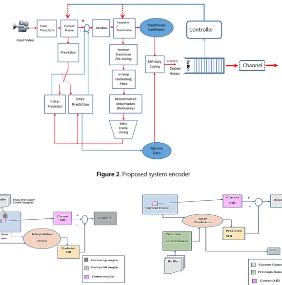
At this section the controller is incorporated to be used with H264 encoder stander at specific configurations that represent the contribution of this article, see Fig.2.
100
A video sequence of QCIF, CIF or HD formats is used as input to the system. The input video sequence will be divided into cycles, where the cycle start with Intra (I) frame and followed by a number of predicted (P) and bi-predicted (B) frames. Each frame is divided into slices of many macroblocks. The encoder forms the prediction of the current block either from the current frame using intra prediction to remove spatial redundancy as in Fig.3, or from other frames that have already been coded and transmitted using inter prediction to remove temporal redundancy as in Fig.4. A residual error then produced by subtracting the prediction from the current block. This residual block is then transformed, quantized and finally encoded to be streamed over the channel, as shown in Fig.2. These steps will be described through the system operation and explination in the next subsections.
Figure 2. Proposed system encoder
101
3.1 Prediction Mode
In this subsection the mechanism applying prediction as intra or inter one will be defined. Intra prediction is carried out by using the different modes (0-9), applying the best matched one applied in the same frame as spatial prediction, see Figure.3.Tree block size 16×16 to 4×4 are used for luma components, and one of 8×8 block size is used for each chroma components, all types are considered in this work. As mentioned previously, for each block size, different prediction modes are used, the 16×16 block size has 4-modes, while the 4×4 has 9-modes and 8×8 chroma block has 4- modes. The Sum of Absolute Errors (SAE), as defined in Eq.1, is calculated to indicate the error magnitude that is used in finding best matching. The best mode that will be selected is the mode that has minimum SAE.
SAE = (1)
Where; C (i, j) is the current sample and P (i, j) is the predicted samples.
The decision to choose the best block size form 16×16 or 4×4 luma block size is based on rate-distortion cost calculation, defined previously, as steps of implementation in this work is described in Fig.3, the best block size is of minimum RDO.
RDO=Distortion + λ MODE*Rate (2)
Distortion = (3)
(4) Inter prediction is used to exploit the temporal redundancy between successive frames. It uses backward prediction type for P-frame prediction and backward and forward prediction types for B-frame prediction process. Each partition of inter macroblock is predicted from an area of the same size in a reference picture, by finding the prediction region. Residual is determined by the subtraction of prediction block and the original one. Motion vector (MV) represents the offset displacement between the two origins of the two blocks. H.264 inter prediction achieves considerably higher coding efficiency since it provides mechanizes of; tree structured partitioning, multiple reference frame for prediction, - in Loop de-blocking filter, and quarter pixel accurate motion vectors. Consider a previously reference coded frames, as a source for prediction. Search area of 16×16 is opened on the choice reference frames for block matching, for the best block matching, a process is known as motion estimation. It is the lowest energy in the sum of residual. To generate the best MV of ¼ resolutions, an interpolation of the reference picture(s) need to be achieved. MV represents the relative position for the matching interpolated area in the reference frame. 3.2 H.264 Transform
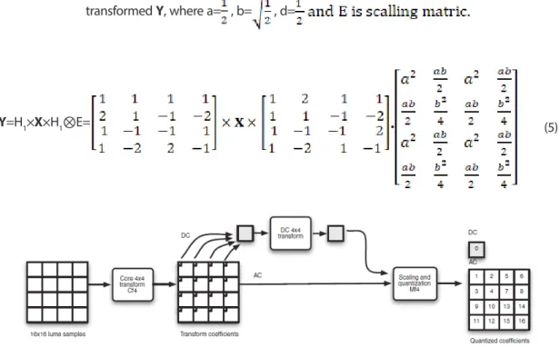
After prediction process, the residual block samples, luminance and chrominance, are transformed using a 4 × 4 integer Discrete Cosine Transform (DCT). Three transforms are used; integer DCT-based transform of 4 × 4 blocks, in additional to two Hadamard transform of 4×4, and of 2 × 2. These transforms templates are used as shown in Fig.5.
102
Where the X 4×4 blocks residual coefficients are transformed using the following equation results of transformed Y, where a= , b= , d=
Y=H1×X×H1⊗E= • (5)
Figure 5. 4×4 block transformation
A 4×4 Hadmard transform will be applied for the residual block 16×16 intra prediction mode, in addition to the integer transform (H1), for all the 16 DC coefficients, where these DC, Ydc, values tend to be highly correlated, as given in Eq.6.
Ydc= /2 (6)
While the Chroma 8×8 blocks components are transformed in four 4×4 using H1, integer DCT transform, results in a 2 ×2 block (dc), that are transformed using Hadmard transform of size 2 ×2 prior to quantization process as in Eq.7.
Ydc= /2 (7)
3.3 Quantization
The resultant of transformed coefficients, Yi,j, of the assigned block are quantized, Qi,j, using Eq.8. In this work a set of 52 values are used as allowed within H.264 stander.
103
Q(i, j) = round (8)
After quantization process each 4×4 block of quantized coefficients is converted to 1-D 16 array using zig-zag scanning order.
3.4 3.5.8 Entropy Coding
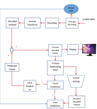
For main profile, the residual blocks, prediction modes, motion vector data are encoded by using Context Adaptive Binary Arithmetic Coding (CABAC), as shown in Fig.6. Figure (7) shows the decoder block diagram, which are the reverse operations of the encoder.
8
Figure 6. 4×4 CABAC block coding
Figure 7. H.264 decoder processing 4. BUFFER OPTIMIZATION AND RATE CONTROL
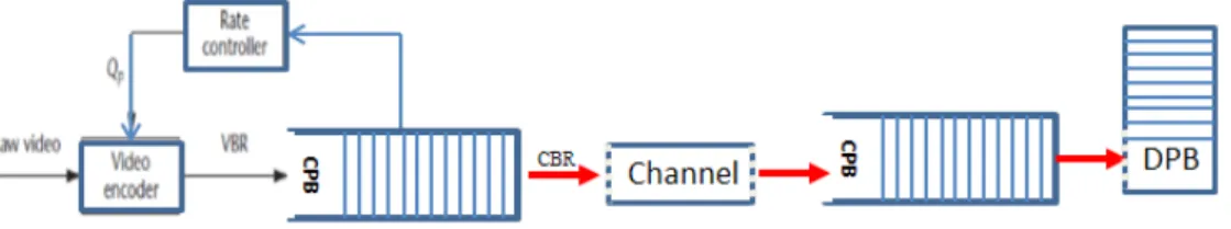
This work manipulates video encoding for applications such as conferencing and video broadcasting that are adopted over the wireless channel, 3G or 4G mobile channel and WiMAX, or over wired channel like ADSL as proposed early. As known the high quality video encoder output is VBR while the communication system channel is a “Constant Bit Rate” (CBR), to map this varying data rate into a CBR channel, the buffer sub system is used, as shown in Fig.8. The coded video data (VBR) is the buffer input while its output is the transmission channel rate. At
Figure 6. 4×4 CABAC block coding
104
4. BUFFER OPTIMIZATION AND RATE CONTROL
This work manipulates video encoding for applications such as conferencing and video broadcasting that are adopted over the wireless channel, 3G or 4G mobile channel and WiMAX, or over wired channel like ADSL as proposed early. As known the high quality video encoder output is VBR while the communication system channel is a “Constant Bit Rate” (CBR), to map this varying data rate into a CBR channel, the buffer sub system is used, as shown in Fig.8. The coded video data (VBR) is the buffer input while its output is the transmission channel rate. At the other side, at receiver, is the decoder buffer, where its input rate is the channel rate while its output is the derived reconstructed frames. Video quality and output rate of the video encoder is controlled by the rate controller subsystem by feedback signal based on the buffer level statues. The system as designed reduces end to end delay, by encoder compression mechanism, and keeps of data flow by control buffer from over flow and under flow with the help of rate controller. Buffering system is designed at size depending of the initial delay time at the decoder, a delay that allowed for video signal decoding corresponding to time transmitting. In this work such delay is in term of not more than 1mSec, which is mostly within the allowable time delay. The buffering subsystem sends control signal to the controller rate subsystem when the accumulated data at encoder buffer reaches maximum allowable accumulated data. The allowable encoder accumulated data is calculated as in Eq.9.
Maximum accumulated data= initial delay time × channel data rate (9) When the accumulated data at buffer reaches the maximum accumulated data, alarm signal is sent to the controller to take an action of bit rate reduction, like increasing quantization step value, increasing GOP length, introduce interpolation mechanism, introducing partitioning, or others as mentioned early. This action avoids over flow. In the same time there is a minimum buffer level not allowed to reach lower of it to avoid under flow, where another alarm signal is sent used by the controller to take an action of increasing the bitrate using opposite action of that used for increasing the bitrate. Each of the tools of controlling the bitrate is arranged in lookup tables, a table for each tool. For example of what are used in this work, the 52 quantization step values are arranged in ascending order, where increasing order takes action of reducing bitrate while decreasing the order decreasing the bitrate. The priorities of using the tools are arranger as follows; QP, GOP, and skip frames are used adaptively as controller parameters, while partitioning, number of references and interpolation are used in full ranges as possible depending of system hardware size. More calculations will be considered in results chapter where scenarios of using video format and required application channel are considered.
105
5. TESTING RESULTS
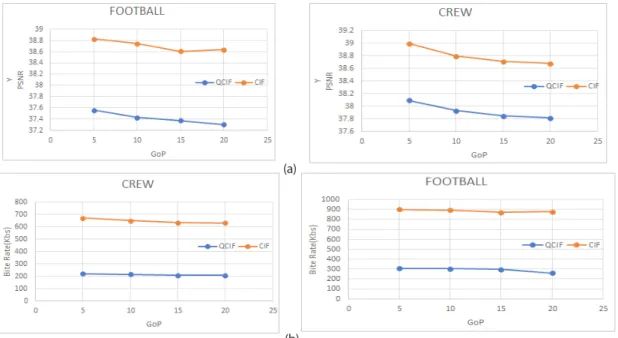
Many configuration scenarios were used for testing H.264 video compression standard based on main profile that is adopted in this work to be used for video broadcasting over 3G and 4G mobile networks. Two video formats were considered CIF (288×352) and QCIF (144×176). After compressing the video sequence; a stream of bits are generated CABAC for main profile. The tested scenarios are reflected to the proposed rate control scheme of encoded bit streams and output quality. The H264 features values of these experiments are fixed of quantization (I QP=25, P QP=25 and B QP=28), GoP of (10),reference frame of (2), frame skipping of (2) and frame rate of 30fps, while the feature under test will be changed to check its effect. Two simulated experiments are carried out for two video clips at different GoP lengths (5, 10, 15 and 20). Fig.9 shows the results of QCIF and CIF formats under the main profile, where the impact of GoP length on the PSNR (a) and encoded bitrate (b) for high motion details video. The results show that increasing the cycle length leads to decreasing in the quality of the decoded video and decreasing the bitrate. This outcome helps us to measure the allowable ranges of used GOP that are incorporated in the controller subsystem. CIF and QCIF result of different resolutions; lead us to introduce transcoding.
(a)
(b)
Figure 9. Impact of changing GoP on H.264 main profile (a) PSNR (b) bitrate
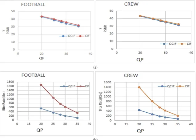
Quantization parameter (QP) is the most important effective parameter of rate control mechanism. A rang of quantization parameters (20, 25, 28, 30, 35) while keeping others are applied. For this work, quantization parameter specifically takes high priority due to its effects in the implementation of the controller for its direct effects and simplicity in implementation. Scenario is designed to test the quantization parameter effects under main profile. Fig.10 illustrates the effect of quantization parameter on the peak signal to noise ratio and encoded bit rate for Football and Crew clips. This figure, presents a road map for available mobile service based on 3G, which show to get 2Mbs for indoor applications the two formats
106
with the suggested range of quantization values result of minimum PSNR more than 30db, which can be applied to get proper video quality. When we are applying for outdoor of 384Kbs the CIF can be applied at quantization value more than 30 less than 35. While when we are applying for high speed vehicles at 144Kbps only QCIF with QP not less than 35 must be used. It is clear from these experiments how QP can be used for channel streaming adaptation.
(a)
(b)
Figure 10. Quantization parameter effect on H.264 main profile performance (a) PSNR (b) Bitrate
Fig.10 clearly shows that increasing the quantization parameter has direct and quick effect of decreasing PSNR and bit rate, for this reason it is used as the solution for the emergency cases of buffer overflow and underflow. Such analysis is the guide of designing the controller where quantization parameters are mainly used to reduce bitrate while the other tools are used in smoothing the effects of quantization parameters to keep of reasonable PSNR.
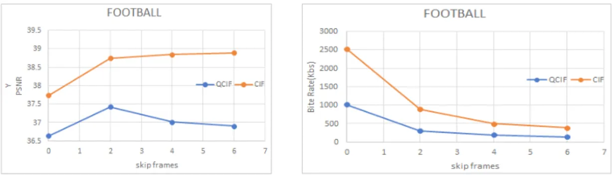
To study the effect of frame dropping on the bitrate and decoded video quality an experiment is carried out for video sequence of 15 frames with different frame dropping values (0, 2, 4, and 6) with CIF and QCIF while others are fixed. Fig.11 shows the impact of frame dropping on the PSNR (a) and encoded bitrate (b) under main profile. The figure shows that increasing of frame dropping leads to slightly decreasing of quality of the decoded video with clearly decreases of bitrate at increasing the number of frame dropping. Dropping of 6 frames from total sequence of 15 still gives acceptable PSNR, which shows the effect of such technique of bitrate controlling.
107 Figure 11. H264 main profile frame dropping performance test (a) PSNR and (b) bitrate
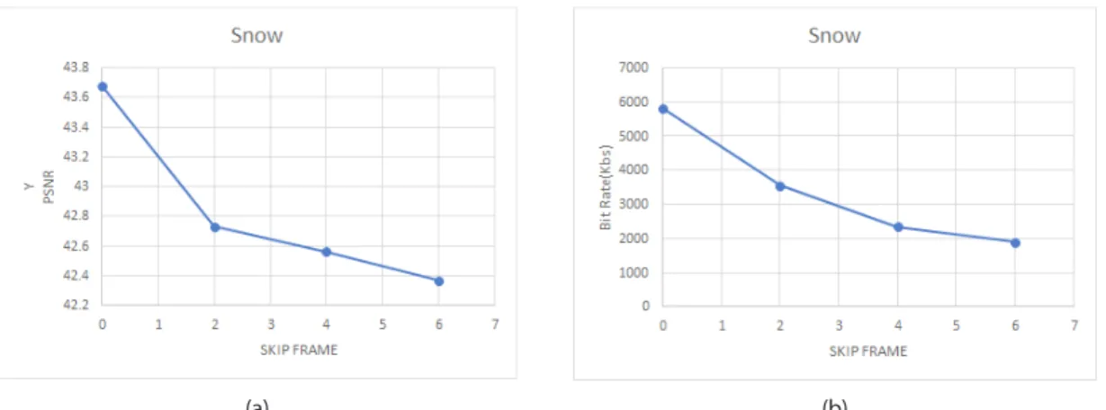
Figures 12, 13, and 14 are the tests of GOP, QP, and skip frames parameters effect measurements of PSNR and bitrate of the main profile HD format snow videos with the same features as above.
(a) (b)
Figure 12. H.264 HD main profile format GOP range (a) PSNR (b) bitrate
(a) (b)
108
(a) (b)
Figure 14. H.264 HD main profile format quantization range (a) PSNR (b) bitrate
P-Reference frames number is one of the tools parameters that have an effect of the PSNR and bitrate. This parameter has its smooth effect that it is used in this work with allowable range of H264, where the limitations are the available hardware. Generally scenario test studies the impact of the number of the P reference frames on PSNR, bitrate. For main profile CIF and QCIF video format, a sequence of 30 frame video is encoded based on a different number of reference frames (1, 2, 3, and 4). The quantization parameter is set to 28 at GOP of (10). Fig.15 displays the performance for the tested scenario of H.264 main profile, in comparison with extended profile.
(a) (b)
Figure 15. H264 main profile number of references performance test (a) PSNR and (b) bitrate
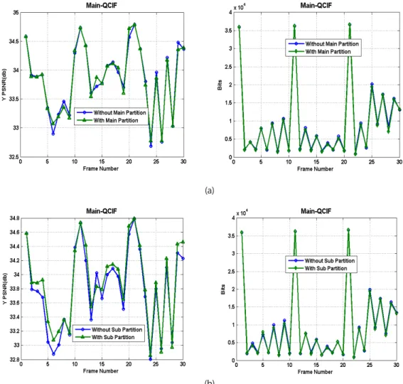
For QCIF, this figure shows that increasing the number of reference frames reduces bitrate about 12% while slightly reducing PSNR. We need to pay for additional processing and intermediate area memory saving. H264 inter frames, P and B frames, use partitioning and skip modes to achieve reduction in bitrate and improving of quality. For partitioning of prediction modes of main partitions (16×16, 16×8, 8×16) and sub-partition modes are tested for foreman video clips of 30 CIF and QCIF formats with number of reference frame 2, frame rate=30fps, fixed QP =28, Gop = 15 and skip frame =0. Fig.16 shows the
109 results for the main profile H.264 encoder. The results show that PSNR and bitrate are enhanced when
partitioning technique is used.
(a)
(b)
Figure 16. H.264 main profile Prediction Modes in (a) Main Partitioning): (b) sub-partitioning
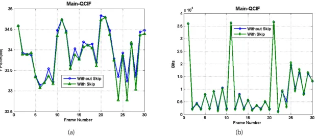
The skip mode is applied for macroblock skipping. Skip means drop (16×16) macroblock that has very similarity with previous ones to reduce computational complexity as well as the encoded bits. Fig.17 shows applying skip mode on the decoded frame quality and bitrate of main profile. The figure shows that degradation in the PSNR when using the skip mode with reduction of inter frames bitrate.
110
15
(a)
(b)
Figure 17. H.264 main profile skip Modes (a) PSNR (b) Encoded bits per frame
The sub-pixel motion estimation feature over 30 frames QP=28 and GoP=10 is applied, Hata!
Başvuru kaynağı bulunamadı. shows the results effects of PSNR and bitrate of main profile.
Sub-pixel motion estimation gives best quality with reduced bitrate of 9% for QCIF and 17% for
CIF.
(a)
(b)
Figure 18. H.264 main profile Sub-Pixel Motion Estimation in: (a) PSNR (b) bitrate
6. BUFFERING OPTIMIZATION
(a) (b)
Figure 17. H.264 main profile skip Modes (a) PSNR (b) Encoded bits per frame
The sub-pixel motion estimation feature over 30 frames QP=28 and GoP=10 is applied, Fig.18 shows the results effects of PSNR and bitrate of main profile. Sub-pixel motion estimation gives best quality with reduced bitrate of 9% for QCIF and 17% for CIF.
(a) (b)
Figure 18. H.264 main profile Sub-Pixel Motion Estimation in: (a) PSNR (b) bitrate
6. BUFFERING OPTIMIZATION
In this subsection the buffering system is analysed due to buffer status over the time operation. For a buffer of size 500Kbit, two observations are recorded one for QCIF and HD formats. A 30 frames at QP=28 QCIF format under 384 Kbps channel buffer status is shown in Fig. 19 with initial removal delay of 0.2msec.
111
(a) (b)
Figure 19. Buffer Occupancy (a) Encoder (b) Decoder
The second observation is done for HD format for 30 frames per second at buffer size of 8Mbits over a channel of 2Mbps (3G indoor application), see Fig.20.
(a) (b)
Figure 20. HD format (a) encoder (b) decoder
7. CONCLUSION
The main topic of this study is how to use the different tests for the purpose of bitrate control to achieve an assigned goal of PSNR. The H264 CODEC features; QP, GOP, skip frames, Skip MB, Sub pixel ME and Number of reference frames are used and tested with main profile of CABAC coding technique for broadcasting application. The using of reference number, Sub pixel ME and size of macroblock partitioning are depending of available hardware, where increasing of them need more hardware spaces and speed,
112
while frame dropping, GoP and QP play an effective roles in the rate and PSNR video quality, since encoded bits and PSNR are decreased with increasing them, so they are used as an adaptive features dynamically changed corresponding to the channel state. The encoder buffer is used to sense the channel, where the threshold, under threshold and over threshold buffer levels are the mechanism of channel sensing. The controller sub-system is applied as the adaptive mechanism of video streaming over the channel. A more than 50% bitrate saving is achieved, compared with previous stander, with keeping of video quality within required ranges that guaranty accepted PSNR.
8. REFERENCES
Cisco, 2019. Cisco VNI Global IP Traffic Forecast. 2014-2019. 2019. url: \url{http: //www.cisco.com/c/en/ us/solutions/collateral/serviceprovider/visual-networking-index-vni/VNI_Hyperconnectivity_ WP.html}. Conklin Gregory J. 2001,” Video Coding For Streaming Media Delivery On The Internet” IEEE TRANSACTIONS ON CIRCUITS AND SYSTEMS FOR VIDEO TECHNOLOGY, VOL. 11, NO. 3.
Joshi Madhuri A., Raval Mehul S., Dandawate Yogesh H., Joshi Kalyani R., Metkar Shilpa P., 2015. Image and Video Compression Fundamentals, Techniques, and Applications.
Karmakar G. and Dooley L.S.,2008. Mobile Multimedia Communications: Concepts, Applications, and Challenges. IGI Global.
Khalil I. and . Weippl E., 2011. Innovations in Mobile Multimedia Communications and Applications: New Technologies. IGI Global.
Mamatha R. and Keshaveni N., 2014 “Comparative Study of Video Compression Techniques- H264/AVC,” Int. J. Adv. Res. Comput. Sci. Softw. Eng. Res., vol. 4, no. 11, pp. 874–877.
Meraj M.and Kumar S., 2015. “Evolution of Mobile Wireless Technology from 0G to 5G .,” Int. J. Comput. Sci. Inf. Technol., vol. 6, no. 3, pp. 2545–2551.
Yun Q. and Sun H., 2000. Image and Video Compression for multimedia engineering: Fundamentals, Algorithms, and Standards.