Realistic Rendering and Animation of a Multi-Layered Human Body Model
Mehmet S¸ahin Yes¸il and Uˇgur G¨ud¨ukbay
Dept. of Computer Engineering, Bilkent University, Bilkent 06800 Ankara, Turkey
email: [email protected], [email protected]
Abstract
A framework for realistic rendering of a multi-layered hu-man body model is proposed in this paper. The huhu-man model is composed of three layers: skeleton, muscle, and skin. The skeleton layer, represented by a set of joints and bones, controls the animation of the human body using in-verse kinematics. Muscles are represented with action lines that are defined by a set of control points. An action line applies the force produced by a muscle on the bones and on the skin mesh. The skin layer is modeled as a 3D mesh and deformed during animation by binding the skin layer to both the skeleton and muscle layers. The skin is deformed by a two-step algorithm according to the current state of the skeleton and muscle layers. Performance experiments show that it is possible to obtain real-time frame rates for a moderately complex human model containing approxi-mately 33,000 triangles on the skin layer.
Keywords: multi-layered human models, action line,
skinning, rendering, inverse kinematics.
1
Introduction
This paper proposes an anatomically based, layered struc-ture of the human body. The strucstruc-ture is composed of three layers: a skeleton layer, a muscle layer and a skin layer. Our model is similar to the multi-layered anatomically based models of Wilhelms and Van Gelder [1] and Scheepers et al. [2]. The proposed method is an efficient method that realistically deform the skin layer based on the transforma-tions of the inner layers.
The skeleton layer is composed of joints and bones and controls the motion of the body by manipulating the joint angles. The articulated body structure is based on the
Hu-manoid Animation (H-Anim) standard, which is developed
by Humanoid Animation Working Group of Web3D Con-sortium [3]. We used Extensible Markup Language (XML) data format to represent the skeleton. The motion of the skeleton is controlled by inverse kinematics. Inverse kine-matics problem is solved by means of a package, named
Inverse Kinematics using Analytical Methods (IKAN), that
provides the required functionality for controlling the mo-tion of the body parts like arms and legs [4].
The muscle layer represents the muscular structure of the human body. We control the deformation of the muscle through the joint angles of the skeleton layer under the fol-lowing constraint: the insertion/origin points of the muscles on the bones are attached during animation and form the action lines. In our system, the muscle layer is represented only by action lines and the muscle shape is not considered. An action line denotes the imaginary line along which the force exerted onto the bone is produced. This line also in-cludes the forces exerted onto the skin layer that create the skin deformation due to muscular motion during the anima-tion. We represented some fusiform muscles in the upper and lower parts of the legs and arms.
The skin layer is represented as a 3D mesh and contains 53 parts. The skin layer is deformed according to the move-ments of the joints in the skeleton layer and the forces ap-plied by the muscle layer. To deform the skin layer realis-tically during animation, we bind the vertices on the skin layer to the joints of the skeleton layer and to the action lines of the muscle layer simultaneously. This binding op-eration is performed in three steps. In the first step, for each part of the skin mesh, a particular joint of the skeleton is determined and the vertices in this part are attached to the selected joint. The second step deals with binding some vertices, especially the ones closer to the joints, to more than one joint. In the last step, some problematic vertices are handled manually. After attaching skin vertices to the skeleton, we also bind them to the muscles. The skin mesh is deformed based on skeletal and muscular deformations.
2
Related Work
In the early stages, we see humans represented as simple ar-ticulated bodies made of segments and joints (stick figures). These articulated bodies were simulated using kinematics-based methods. More recently, dynamic methods have been used to improve the reality of the movement. Since the hu-man body is a collection of complex rigid and non-rigid components that are very difficult to model, these dynamic
and kinematics models did not meet the needs. Conse-quently, researchers began to use human anatomy to pro-duce human models with more realistic behaviors. The models proposed for the representation and deformation of human body can be divided into four categories: stick
fig-ure models, surface models, volume models, and and multi-layered models.
Layered approach is used both in construction and an-imation of characters. There are two groups of models. The first group relies on a combination of techniques like skinning and implicit surfaces and tends to produce a sin-gle layer from several anatomical layers. The other group is inspired by the actual biology of the human body. These models try to represent and deform every major anatomical layer and model the dynamic interactions between them.
The skeleton layer is an articulated structure that pro-vides the foundation for controlling the motion [5]. Some-times, the articulated structure is covered by material bones approximated by simple geometric primitives [2].
Muscle layer was first used by Chadwick et al. [6]. Since an ellipsoid approximates quite well the appearance of a fusiform muscle, muscle models tend to use the ellipsoid as the basic building block when the deformation is purely ge-ometric. Moreover, the analytic formulation of an ellipsoid provides scalability. Hence, volume-preserving ellipsoids are widely used for representing fusiform muscles [1, 2].
Implicit surfaces are widely used to model the muscle layer. In [7], implicit primitives like spheres and super-quadrics are used to approximate muscles. In [5], the gross behavior of bones, muscles, and fat are approximated by grouped ellipsoidal metaballs with a simplified quadratic field function. This technique does not produce realistic results for highly mobile parts, in which each primitive is simultaneously influenced by several joints.
A polyline called “action line” is introduced by Nedel and Thalmann [8]. The action line is used to represent mus-cles at an abstract level. It represents the force produced by a muscle on the bones and a surface mesh deformed by an equivalent mass-spring network. An noteworthy feature of this study is the introduction of angular springs, which are are very useful to smooth out the surface and to control the volume variation of the muscle.
B-spline solids can also be used for modeling muscles, as described by Ng-Thow-Hing [9]. The advantage of using B-spline solids for modeling muscles is that B-spline solids can capture the various muscle shapes (fusiform, triangular, etc.) and can also render attachments of different sizes.
Polygonal, parametric, subdivision, and implicit surfaces have been used for modeling the skin. Polygonal surfaces are preferred because they are processed by graphics hard-ware. However, some surface discontinuities, which are required to be smoothed out, may arise when polygonal surfaces are used. Parametric surfaces yield very smooth
shapes. This makes them very attractive for modeling the skin. Implicit surfaces are also used to represent organic forms. The main limitation of them is that it is difficult or even impossible to apply texture maps. Therefore, they are very seldom used for directly extracting a skin and used frequently for invisible anatomical layers. Subdivision sur-faces are also very popular for representing the skin layer. The skin can be deformed by using one the following meth-ods in multi-layered models [10]:
Surface deformations are applied to the skin and the skin is projected back onto the inner anatomical layers. A mechanical model is used to deform the skin while keeping the skin a certain distance away from the ma-terial beneath.
The skin is defined as the surface of a volume finite element (mass-spring model of the body).
3
Skeleton Layer
The skeleton, which is defined by a set of joints and bones, is the layer that determines the general shape of a body. A tree structure is used to represent the relationships between the joints. In this work, the H-Anim 1.1 compliant human body model is used. XML data format is used to represent the skeleton. The system uses inverse kinematic methods for low-level motion control. Positions, joint angles, forces, torques and other motion parameters are specified manu-ally. Spline-driven animation techniques are chosen to spec-ify the characteristics of the motion. The paths for pelvis, ankle and wrist motions are specified by Cardinal splines. Detailed information about high-level motion control using these low-level techniques can be found in [11].
4
Muscle Layer
While the skeleton creates the general structure of the body, muscles determine the general shape of the surface mesh. Human body movements require muscles to perform differ-ent tasks; thus, human body includes three types of muscles;
cardiac, smooth, and skeletal. Cardiac and smooth muscles
are called involuntary muscles, because they cannot be con-sciously controlled. On the other hand, Skeletal muscles put into practice the voluntary movements. They are attached to bones by tendons and provide us the capability to perform various actions by simply contracting and pulling the bones they are attached to towards each other. In this study, only skeletal muscles are modeled because we aimed to represent only the external appearance of the human body.
Skeletal muscles are located on top of bones and other muscles, and they are structured side by side and in layers.
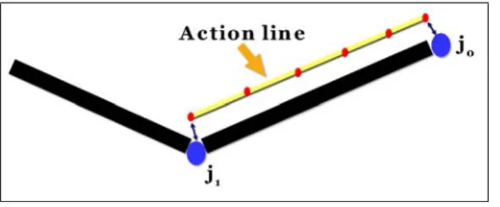
Figure 1: Action line abstraction of a muscle
A skeletal muscle is a contractile material that originates from fixed origin locations on one or more bones and inserts into fixed insertion locations on one or more other bones [12]. The relative positions of these origins and insertions determine the diameter and shape of the muscle. In a real human, muscle contraction causes joint motion but in our implementation, muscles deform due to the joint motion.
In most muscle models, a muscle is represented using two levels: the action line and the muscle shape. However, we represented the muscle layer only with action lines and did not consider the muscle shape as seen in Figure 1. We modeled muscles in the upper arms, upper legs and lower legs. The key idea of our approach is that the deformations of the skin mesh are driven by only the underlying action lines and no muscle shape is considered.
An action line denotes the imaginary line along which the force applied onto the bone is produced [10]. Many re-searchers assume the action line as a straight line, but the most common approach represents the action line as a se-ries of line segments [13]. These segments are determined depending on the anatomy of the muscle. An action line is the representative of the muscle force at a cross-section.
We represent muscles by action lines that simulate the muscle forces. Each muscle is defined by an origin and in-sertion point. We represent the actions lines as polylines, as described in [13]. For this purpose, we used some control points, which are responsible for guiding the line and deter-mining the forces exerted onto the skin mesh. These force fields are inversely proportional to the length of the corre-sponding action line segment. An example of this kind of action line is shown in Figure 2.
We deform the skin layer based on the underlying bones and action lines. This makes the 3D nature of the defor-mation problem to be reduced to one dimension. Each ac-tion line is modeled by a polyline and these polylines in-clude some number of control points. The control points that correspond to the insertion and origin of the muscle are attached to the skeleton joints so that their motion is dictated by the skeleton. The positions of all the remaining control points are obtained by linear interpolation for each frame.
Since the positions of the control points provide
infor-Figure 2: The structure of an action line: control points and forces on these points
mation as to how the surface mesh will expand or shrink over time, we need to determine the local frame of each ac-tion line control point. Then, an acac-tion line can be animated with respect to the underlying skeleton. Since the insertion and origin points of the action line are fixed on the skeleton, when the skeleton layer moves, this movement is reflected to the action line as a decrease or increase in length. As a result, the lengths of action line segments change. The force fields on each control point are inversely proportional with the segment length. The next step is the deformation of the skin mesh due to the changes on the forces applied on skin vertices by the action line control points. This de-formation is automatically propagated on the skin layer via the anchors between skin vertices and action line. If the segment length shortens, the force fields increase and make the skin mesh to bump. The elongation in length results in decrease in force fields and relaxation of skin mesh.
5
Skin Layer
The skin layer can be modeled in three ways. The first ap-proach is creating it from scratch or modifying an existing mesh in a 3D modeler. Another approach is to laser scan a real person that produces a dense mesh that truly represents a human figure. The last method for modeling the skin layer is extracting it from the underlying components if available. The skin mesh is created by a 3D modeler, called Poser [14]. We use P3 Nude Man model of the Poser software. The model has 17,953 vertices and 33,234 faces. The whole body is composed of 53 parts, like hip, abdomen, head, right leg, left hand, etc. This structure provides us the required functionality for binding vertices to the inner layers.
Due to the deformation of the underlying skeletal and muscular layers, we deform the skin mesh. This is done by positioning the skin vertices according to the skeletal defor-mation and moving them along the vertex normals to simu-late the action of the muscular system. In this stage, called
attaching, each skin vertex is associated with the closest
a skin vertex is attached to the nearest point on its under-lying component. This provides the functionality that the shape changes in the underlying component are propagated through the anchors to the corresponding skin vertices.
In this step, we aim two goals: simulating the movement of the skin layer according to the skeleton layer, and based on this, generating a smooth skin appearance. Skin vertices are attached to the joints of the skeleton layer in a multi-step algorithm. In fact, the skin vertices move with the limbs in the underlying skeleton. However, we attach the skin vertices to the joints that the limbs are attached since the limbs move according to the coordinate systems attached with the joints. We now describe the skinning-based surface deformation process, which is based on [15].
The skin model is decomposed into parts, which are groups of vertices in different regions of the body. In the first step, we determine a particular joint for each part of the skin and attach the vertices of this part to this joint. For example, the right upper arm is attached to the right shoul-der joint and left thigh is attached to the left hip joint (Fig-ure 3). This binding proced(Fig-ure dictates the positions of the body parts when the underlying joint orientation changes. To attach a skin part to a joint, the vertices are transformed into the joint’s coordinate system. This transformation is achieved with the following equation:
(1) where is the parent of joint and is the coor-dinate transformation matrix from to . Besides, the movement of the skeleton requires a rotation at joint de-noted by the transformation matrix . Hence, the final transformation for the joint is given by:
(2) The new position of the skin vertex attached to the joint can be calculated according to Equation 3:
(3) The first step is not sufficient for realistic deformation of the skin layer. This is because of the changes in the posi-tions of the attached bones of the skin vertices that are very close to the joints. To obtain a realistic skin deformation, some vertices near the joints are attached to more than one bone, which is called “vertex blending” [15]. If vertex is attached to joints , the resulting vertex position can be calculated as:
(4)
where , are the weights of the
attach-ment of vertex to joint and the sum of the weights is equal to 1.
Figure 3: The attachment process: the right upper arm is bound to the right shoulder joint and the left thigh is bound to the left hip joint.
Figure 4: Skinning in our implementation: some vertices near joints are attached to two joints based on a threshold.
We improved the implementation of the skinning process in the following way to get more realistic results. We at-tach the vertices near the joints to both the closest joint and one adjacent joint. The second step of the attaching process is focused on determining the skin vertices that have to be bound to an adjacent joint in this way. For this purpose, we set a distance threshold for the joints, left elbow, right elbow, left knee, and right knee. For the vertices around these joints, if the distance between the vertex and the joint is smaller than the threshold value, this vertex is also bound to that joint with an appropriate weight in addition to the joint it is bound in the first step (see Figure 4).
6
Experimental Results
It is not very easy to determine the appropriate distance value for the binding operation that works in all cases. If
we use a smaller threshold value, some of the vertices that should be attached are not attached with the joints. For ex-ample, some vertices of the back part of the hip need to be attached to the left hip or right hip joints in order to gener-ate a realistic walking motion. However, since the distance of these vertices to the corresponding joints are greater than the threshold value, undesired holes are generated during animation. As a solution, we tried to increase the threshold value. Unfortunately, this attempt caused unnatural results for the other parts of the body during movement.
Therefore, contrary to the first two steps, which are fully automatic, we implemented a manual step to overcome the deficiencies. This last step includes selecting some of the unattached vertices manually by using mouse and binding them to the appropriate joints. Then, a weighting scheme assigns weights to the selected vertices. The weights are in-versely proportional to the distance between the vertex and the joint. As a result, these selected vertices are influenced by both the closest joint and the parent of this joint with appropriate weights.
The muscular deformation is based on the control points of the action lines. Due to the skeletal deformations, the length of the action line and the lengths of each segment of the action line change. The lengths of the segments are in-versely proportional to the forces acting on the skin mesh. The forces on the skin mesh increase when the lengths of these segments decrease, which generate muscle bulging ef-fects on the skin. These forces are propagated to the skin layer via the anchors between the skin vertices and action line control points.
To perform the muscular deformation, we first attach each skin vertex to the underlying action lines. This can be achieved by a similar process of attaching skin vertices to skeleton. In the skin-skeleton mapping algorithm, all ver-tices in a body part are bound to a particular joint. In skin-action line binding process, each vertex is attached to a par-ticular action line. An action line is composed of a set of control points and each control point has a different force field on the skin mesh (see Figure 2). Hence, we have to bind each vertex to a number of control points of the action line. We select the nearest three control points for a vertex so that the vertex is affected by these three points. On each control point, we determine force fields according to the to the type and position of the muscle. For example, in Fig-ure 2, if we consider the action line as a muscle in the upper arm, the has a higher magnitude than the forces and . This is because the upper arm muscle generates more deformation on y-direction than the other directions. In the development stage, we tried different force magnitudes in order to get a realistic skin deformation and found optimum force values for each muscle and its control points. Our im-plementation enables the user to modify the force values.
The next step is to determine how the skin vertices are
(a) (b)
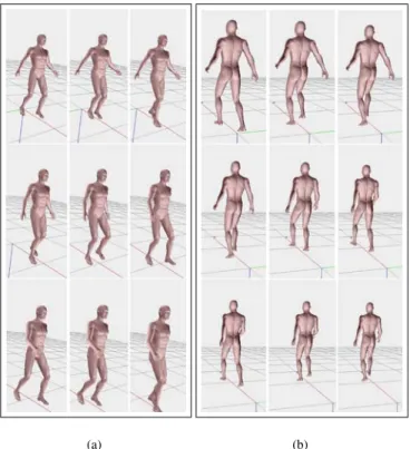
Figure 5: Human walking: (a) front view; (b) back view.
affected from the nearest three control points. Each control point , , has a weight associated with the skin ver-tex , which determines the effect of the control point on the skin vertex. The weight is inversely proportional to the distance between skin vertex and control point. The sum of the three weights , , and is equal to 1. Then, the weight for each control point is distributed between the force fields exerted from the control point. This distribu-tion is inversely propordistribu-tional to the angle between the force vector and the vector from the control point to the skin ver-tex. In this way, we determine a weight for all force fields exerted from the action line control points to the the skin vertices. These variations are then propagated to the skin vertices as displacements.
The front and back views of the walking behavior produced by our system are shown in Figure 5. Sam-ple animations for different behaviors can be found in http://www.cs.bilkent.edu.tr/ gudukbay/
HumanModeling/SampleMotions.html. Figure
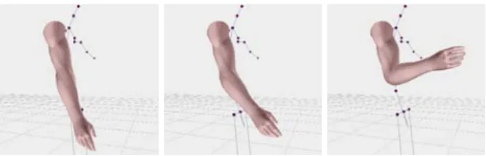
6 demonstrates deformation on the skin mesh due to muscle bulging where the arm is raised forward and then flexed. The visual results show that our system is capable of generating realistic rendering of the human walking behavior. There is no holes or wrinkles on the skin mesh, even near the highly movable joints like shoulders, hips and knees.
Figure 6: Muscular deformation on the skin mesh.
No of No of No of vert. No of vert. Frame vertices triangles bound to bound to rate
one joint two joints (fps)
17,953 33,234 15,305 2,648 19 8,923 15,203 7,623 1,270 48 5,133 7,625 4,189 944 92
Table 1: Performance evaluation results
We implemented the proposed system in a PC platform with Pentium IV 2.4 GHz CPU, 512 MB Memory and 128 MB GeForce4 Ti 4200 graphics card. The software plat-form was Microsoft Visual C++ 6.0 with OpenGL libraries. Original human model is composed of a skin mesh that con-tains 17,953 vertices and 33,234 faces, a muscle layer, and a skeleton structure with 25 joints and 23 bones. Since bones are simulated with lines, they do not have an significant ef-fect on total performance. The most tedious and time con-suming operation is the binding process of the skin layer with the underlying layers. However, this does not effect the frame rate since it is done as a preprocessing step before the animations. We tested the system with different skin meshes ranging from low to high resolutions. The average frame rates given in terms of frames per second (fps) for different meshes are given in Table 1.
7
Conclusion
In this study, we proposed a framework for the animation of a multi-layered human model. The framework is based on an anatomically based approach that builds layers of the human body: the skeleton, muscle, and skin layers. The skeleton layer is based on the H-Anim 1.1 Specification. By using the skeleton layer, we control the motion of the human body, and with the muscle layer, we can deform the skin layer according to the muscular motion. We intro-duced a simple muscle model that approximates the human anatomy. The deformation of the skin is mostly driven by muscle action lines. Our skin layer is modeled in a 3D mod-eler. The vertices of the skin mesh is attached to the inner layers in such a way that a particular skin vertex is attached to the nearest point on its underlying component. This
pro-vides the functionality that if the shape of the underlying component changes, these changes are propagated through these anchors to the skin layer. Performance evaluations showed that the multi-layered model produces realistic skin deformation in real-time.
References
[1] Wilhelms, J. and Van Gelder, A., “Anatomically based mod-eling”, ACM Comp. Graph. (Proc. of SIGGRAPH’97), pp. 173-180, 1997.
[2] Scheepers, F., Parent, R., Carlson, W. and May, S., “Anatomy based modeling of the human musculature”, ACM Comp. Graph. (Proc. of SIGGRAPH’97), pp. 163-172, 1997. [3] Humanoid Animation Working Group of
Web3D Consortium, “Specification for a Stan-dard Humanoid”, Version 1.1, available at
http://h-anim.org/Specifications/H-Anim1.1. [4] Deepak, T., Goswami, A., Badler, N., “Real-time inverse
kinematics techniques for anthropomorphic limbs”, Graph-ical Models, Vol. 62, No. 5, pp. 353-388, 2000.
[5] Thalmann, D., Shen, J., and Chauvineau, E., “Fast hu-man body deformations for animation and VR applications”, Proc. of Computer Graphics Int., pp. 166-174, 1996. [6] Chadwick, J., Haumann, D. and Parent, R., “Layered
con-struction for deformable animated characters”, ACM Comp. Graph. (Proc. of SIGGRAPH’89), pp. 243-252, 1989. [7] Turner, R. and Thalmann, D., “The elastic surface layer
model for animated character construction”, Proc. of the Computer Graphics Int., pp. 399-412, 1993.
[8] Nedel, L. and Thalmann, D., “Real time muscle deforma-tions using mass-spring systems”, Proc. of Computer Graph-ics Int. (CGI’98), pp. 156-165, 1998.
[9] Ng-Thow-Hing, V., “Anatomically-based models for physi-cal and geometric reconstruction of humans and other ani-mals”, Ph.D. Thesis, University of Toronto, 2000.
[10] Aubel, A., “Anatomically-based human body deformations”, Ph.D. Thesis, No 2573, Ecole Polytechnique Federale de Lausanne, 2002.
[11] Memis¸o˘glu, A., “Human motion control using inverse kine-matics”, MS. Thesis, Dept. of Computer Eng., Bilkent Uni-versity, 2003.
[12] Richer, P., “Trait´e d’anatomie artistique”, Biblioth`eque de l’image, 1996.
[13] Delp, S.L. and Loan, J.P., “A computational framework for simulating and analyzing human and animal movement”, IEEE Computing in Science & Engineering, Vol. 2, No. 5, pp. 46-55, Sept-Oct 2000.
[14] “MetaCreations Software”, Poser 4, available at
http://www.metacreations.com/products/poser. [15] Kavan, L. and Zara, J., “Real time skin deformation with
bones blending”, WSCG’2003 Short Papers, University of West Bohemia, Pilsen, Czech Republic, pp. 69-74, 2003.