Mode Matrix Tranceiver Surface Coil
Taner Demir1, Esra Abaci Turk1,2, and Ergin Atalar1,21UMRAM, Bilkent University, Ankara, Turkey, 2Electrical and Electronics Engineering, Bilkent University, Ankara, Turkey
Introduction: The transmit array technology is continuously developing since it was first mentioned by Zhu [1] and Katscher [2]. The transmit array system can
transmit RF power independently from multiple channels and therefore the phase, amplitude and shape of the individual RF pulses for each channel can be programmed individually. This flexibility of transmit array gives us the possibility to increase the B1 field homogeneity while reducing the amount of transmitted RF power. Some RF coils that are compatible with transmit array systems have been developed earlier [3-5]. In this work, a novel surface transceiver coil system is proposed. In the proposed system, three coil elements are grouped together and they are excited using a mode-matrix circuit to create circular (CP), reverse circular (TRIPLE) and left-right linear (DUAL) polarized fields. While adaptation of this coil system to an 8 transmitter and 18 receiver channel system is planned, for this study, the concept of exciting three coil elements from three excitation ports by means of a mode-matrix is proven.
Methods: The mode matrix was originally proposed as a signal precombiner in receive only arrays, scales the number of multiple receive elements down to a lesser
number in order to use the receive channels effectively without a significant loss in signal-to-noise ratio (SNR)[6].
Experiments and Results: The coil is tested in a Siemens TIM TRIO 3T transmit array system. The experiment setup is shown in Figure 2. The coil used in experiment
consists of three rectangular loops with the dimensions of 7x15 cm. Each loop is divided into eight equal length segments by capacitors. The tuning and matching are done for a copper sulphate phantom (2g CuSO4 per 1000g H2O) load. The coil elements are decoupled using capacitors. The coupling between the middle and other loops is -14dB and between right and left loops is -9dB. The MR signals are amplified by separate low input impedance preamplifers with 27dB gain and 0.5 dB noise figure from Siemens. In order to have minimal coupling in the receive mode, preamplifier decoupling is implemented by adjusting the lengths of the cables between the T/R switches and the coils. The 90°- 180° couplers, T/R switches are produced on FR4 printed circuit board by using microstrip transmission lines for handling the higher amount of power effectively. Both couplers have 1° phase and 0.5 dB gain tolerances. The T/R switches have 27dB isolation. It is observed that the usage of baluns on the transmitting cables is very critical for the optimal functioning.
Phantom images for three matrix modes and their B1 maps which are obtained using the Bloch-Siegert method [7] are shown in Figure 3. As seen from figure 3, there is homogeneous field in CP mode. The black holes in the TRIPLE mode verify the existence of the reverse circular polarization. There is a linear polarized field on two sides of the bundle in the DUAL mode and no contribution from the middle loop.
Conclusion: In conclusion, a mode matrix transceiver surface coil concept is introduced. The coil performance is experimentally tested. As a next step, a 18 element
transceiver coil will be constructed using the mode-matrix concept.
References: [1] Zhu Y., et. al. Magn Reson Med. 51(4):775-784, 2004. [2] Katscher U., et. al Magn Reson Med. 49(1):144-150, 2003. [3] Setsompop K., et. al. Magn Reson Med. 56:1163–1171, 2006. [4] Kim K., et. al. Proc Intl Soc Mag Reson Med. 19:3829 2011 [5] Setsompop K., et. al. Magn Reson Med. 60:1422–1432, 2008. [6] Reykowski A, et. al. Proc Intl Soc Mag Reson Med. 11:1587, 2004. [7] Sacolick L. I., et. al. Magn Reson Med. 63(5):1315-1322, 2010.
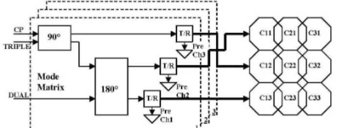
In our design, transmit loops are grouped into bundles of three element coils. Each group is fed by a mode matrix structure as shown in Figure 1. As seen from the figure, in CP mode the transmit channel enters to the 90° coupler. The power is divided into two and half of this power is directed to the middle loop (C12) with zero phase by a transmit-receive (T/R) switch. The other half of the power enters to the 180° coupler and is also divided into two parts. So that one quarter of the overall power is directed to the upper loop (C11) and the other quarter is directed to the lower loop (C13) with ±90° phases via T/R switches. In TRIPLE mode, power ratios of the channels remain similar as in the CP mode while the phases are altered. The DUAL mode is created when the coil is driven from the isolated port of the 180° coupler. In this situation, the power is shared between upper (C11) and lower (C13) loops with 180° phase difference in between which causes a linearly polarized field. The middle loop (C12) has no contribution to the field in DUAL mode. The coil composed of twice the structure in Figure 1. Coil T/R switches + Preamplifiers Plug 90° Coupler λ/4 line 180° Coupler Tx Channels Phantom Figure 1: Mode matrix transceiver surface coil structure
CP TRIPLE DUAL
Figure 2: Experiment setup Figure 3: Phantom images for three matrix modes (at the top) and
B1 maps (at the bottom)