S.N.B. Oliaei
a, Y. Karpat
b,e,f,g, J. Paulo Davim
c, A. Perveen
d,⁎ aAtilim University, Department of Mechanical Engineering, Incek, Ankara, TurkeybBilkent University, Department of Industrial Engineering, Bilkent, Ankara, Turkey cUniversity of Aveiro, Department of Mechanical Engineering, Portugal
dNazarbayev University, Department of Mechanical & Aerospace Engineering, Kazakhstan eDepartment of Mechanical Engineering, Bilkent University, Ankara, Turkey
fUNAM− Institute of Materials Science and Nanotechnology, Turkey gDepartment of Industrial Engineering, Bilkent University, Ankara, Turkey
A R T I C L E I N F O Keywords:
Miniaturization Coating
Electro discharge machining Laser
Grinding Hybrid
A B S T R A C T
Mechanical micromachining is considered as a cost-effective and efficient fabrication technique to produce three dimensional features and free-form surfaces from various engineering materials. Micro cutting tools are an es-sential part of mechanical micromachining and they are exposed to harsh conditions which reduces tool life and adversely affect the economics of the process. The challenge is therefore to maintain the tool rigidity and cutting edge sharpness for extended period of time. Thus, the design, fabrication and durability of micro cutting tools are of significant importance for successful micromachining operations. This review paper aims to provide a com-prehensive understanding about the capabilities, characteristics, and limitations of different fabrication tech-niques used in the manufacturing of micro cutting tools. State-of-the-art micro cutting tool design and coating technology has been presented for various micromachining applications. Possible future research direction and development in thefield of micro tool design and fabrication has also been discussed.
1. Introduction
The miniaturization trend in recent years across many industries such as aerospace, automotive, microelectromechanical systems (MEMS), optics, electronics, biotechnology, and communications re-quires manufacturing of small parts having micro scale features [1–4]. There are numerous key advantages of miniaturization from both manufacturer and customer perspectives, including portability (which reduces the risk of sample contamination and problems due to mis-handling for users of analytical devices), disposability, heat transfer enhancement due to high surface to volume ratios, lower cost of raw material and reduced power consumption [5,6].
In order to realize miniature components, several micro fabrication techniques have been developed. The developed techniques can be classified according to different criteria. In general, they can be divided into two groups [7,8]: micro-system technologies (MST, mask-based fabrication of MEMS(micro-electromechanical system) and integrated circuits) and engineering technologies (MET, tool-based micro-machining techniques). Tool-based micro-fabrication techniques en-compass a large variety of processes, some of them have been devel-oped by scaling-down of conventional machining processes such as
micro-turning, micro milling and micro-drilling. These processes are known as mechanical micromachining processes. There are other pro-cesses, which are based on non-traditional machining technologies such as micro-electrical discharge machining (μ-EDM), micro-electro-che-mical machining (μ-ECM) or a combination of these processes known as hybrid processes, such as EDM/ECM, ultrasonic assisted EDM (US/ EDM), etc. [9]. These techniques have been emerged as a promising technology for the fabrication and realization of miniaturized compo-nents from different engineering materials. These processes not only eliminate the requirements for very expensive clean room facilities but also leave a smaller environmental footprint by completely eliminating chemical materials such as etching solutions, etc. [9], which makes them economically suitable for the fabrication of small batches or single products and prototypes [10].
Among various tool-based micro fabrication technologies, mechan-ical micromachining which uses micro cutting tools with diameters smaller than 1 mm [11–13] plays a key role in producing complex 3D micro-features and free-form surfaces with tight dimensional and geo-metrical tolerances and relatively high material removal rates [14–16]. Although these processes are considered as the scaled-down version of conventional machining processes, the mechanics of machining at
https://doi.org/10.1016/j.jmapro.2018.10.038
Received 4 December 2017; Received in revised form 29 August 2018; Accepted 27 October 2018 ⁎Corresponding author.
E-mail address:[email protected](A. Perveen).
Available online 16 November 2018
micro scale is quite different [17,18] and there are many challenges which should be considered. In micromachining, the uncut chip thick-ness and the grain size of the work material are usually in the same order of magnitude, the feed per tooth value set in the process may be less than the cutting tool edge radius, and the runout of the tool/tool holder/spindle system may be larger than feed per tooth value. These characteristics of micromachining lead to process uncertainties and deviations from expected process outputs due to so called size effects [19]. The effect of material microstructure must be considered where isotropic and homogeneous material assumptions are no longer valid [14,20], Polycrystalline material should be considered as hetero-geneous and discrete material [21], where elastic modulus andflow stress (deformation resistance) changes with respect to the direction of the cutting edge [22,23].
In mechanical micromachining processes, micro tools are the most flexible part of the micro-cutting system, and they have the lowest stiffness in the whole micro cutting process chain. Their geometry and material properties have a substantial effect on the material removal process, micromachining forces, heat generation, tool wear, surface quality [6], burr formation. These are also considered to be the main drawbacks of the mechanical micro machining process due to tool wear and tool deflection [24] which affects part accuracy significantly. Tool condition monitoring of micro cutting tools is different than conven-tional tools as it is difficult to identify worn cutting edges or broken micro tools [25–27]. Since the machined micro-features are achieved and realized as a result of a direct interaction between micro cutting tool and workpiece, the quality and accuracy of the machined features are highly influenced by the strength, dimensional and surface quality of the micro tools. The significant influence of micro tool tolerances and process uncertainties are the main factors responsible for the low pre-dictability of micromachining. Therefore, continuous research efforts in design and fabrication of micro-tools have been reviewed in this paper which is considered tremendously paramount in the area of micro-machining.
2. Applications of micro tools
Due to miniaturization trend, there is an increased demand in fab-rication of micro components. Examples of these kind of micro-features could be micro holes forfiber optics, biomedical filter, micro nozzles used in jet engines, micro mould/die either for micro optics or micro-fluidic devices [28]. There are many studies in the literature where μ-EDM technique has been used to fabricate tools or electrodes which are employed to create micro scale features. Ravi et al. used block EDM fabricated micro-electrode to manufacture circular, triangular, square micro-holes using micro-EDM technique. Kim et al. [29] has exploited reverse EDM to fabricate multiple electrode which later on used to fabricate micro holes array, channel, grooves using micro ECM tech-nique [29]. Kim et al. [30] also fabricated 3D microstructure like micro hemisphere, micro-channel, micro column using micro ECM milling. Ahn et al. used electrochemical micro-drilling to fabricate 8μm dia-meter, 20μm thickness hole on stainless steel. Wu et al. [31] also fab-ricated micro cavity with rectangular and semi-cylindrical island using vibration assisted micro-ECM. Rathod et al. [32] used electrochemical micromachining to fabricate complex micro grooves which may have their application in micro-coolers, micro-reactors, and micro-mixers. Ghosal et al. [33] fabricated micro features of various shape using micro electrochemical sinking and milling. Yong et al. [34] also fabri-cated microelectrode to manufacture micro holes and microstructure using micro ECM as well as electrochemical milling. Similar in-vestigation is also done by Liu et al. [35] with fabrication of complex structure using micro electrochemical milling. MEMS applications use micro holes to facilitate the passing of wire for the interfacing [36]. Other customized micro-features/shapes, 3D features, channels are also paramount for the applications mentioned earlier. Therefore, these applications inevitably require new fabrication techniques, relevant
machine tools technology, and precision metrology as well as micro-scale tools. In order to keep pace with miniaturization trend of micro scale tools, innovative fabrication techniques need to be explored ex-tensively [37]. Another specific applications for micro-scale parts in-clude micro-channels for lab-on-a-chip devices [2], micro heat ex-changers as compact devices for heat transfer enhancement [38], miniaturized gas analysis systems [39], micro-scale rate integrating gyroscopes for navigation systems in aircrafts and guided weapons [40,41], micro-pumps for flow-controlled delivery in micro-fluidic systems [42], micro nozzles for high-temperature jets [1] and micro-cantilevers for scanning tunneling microscopy [43].
3. Materials and coatings
Micro cutting tools can be fabricated from different super hard materials including high speed steel (HSS) [44,10], cubic boron nitride (CBN) [45,46], cermet [4], single crystal diamond (SCD) [47] and polycrystalline diamond (PCD) [48–51]. At the first glance, single crystal diamond seems to be the most suitable material of choice for micro end mill fabrication due to its extreme hardness and the possi-bility to produce very small cutting edge radii (smaller than 100 nm) and consequently reduces machining forces due to smaller minimum uncut chip thickness values, however attritious wear, low fracture toughness and cleavage fracture have been reported as the main drawbacks of SCD cutting tools [52,53]. Furthermore, extremely high hardness of SCD makes the fabrication of SCD tools a difficult task [54]. A second concept for the usage of diamond as a cutting tool material is polycrystalline diamond (PCD) which is mainly fabricated by high-pressure/high temperature sintering process [55]. Due to the presence of cobalt as a binding phase in PCD, it has a superior toughness, or resistance to chipping. Another important advantage of PCD is that, it is isotropic without the crystal orientation dependent cleavage of single crystal diamond [56]. Owing to its high hardness and strength, PCD is extremely difficult to be machined by mechanical methods, especially for feature sizes smaller than 100μm [57]. Very low G-ratio (the ratio of the volume of material removed from PCD to the volume of material removed from the grinding wheel) is the characteristics of PCD grinding [58], which further hinders its widespread application as a material for micro tool fabrication. Additionally, the reactivity of diamond in both SCD and PCD and its chemical-thermal degradation when machining transition metals such as iron or nickel limits their application to the machining of nonferrous materials only [59]. The limitations associated with the use of PCD and SCD, have pushed the industry to use cemented tungsten carbides as the most common material for micro tool fabri-cation. Consequently, most of the micro cutting tools available in the market are composed of cemented tungsten carbide with cobalt as a binder which is fabricated using powder metallurgy technique [60,61]. Therefore, widespread acceptance of tungsten carbide as a material of choice for micro cutting tools is mainly due to its ease of processing, ability to machine ferrous and non-ferrous materials along with its hardness over a broad range of temperatures [2].
The fact is that despite the high strength and hardness of micro tool materials, micro-scaled features fabricated by the end mills can easily be damaged because of various reasons such as: brittle nature of tool materials, harsh micro machining conditions; excessive micro-machining forces due to the ploughing of the material ahead of the cutting tool as a result of large effective negative rake angle and large cutting edge radius to uncut chip thickness ratios along with inefficient design and fabrication. Therefore rapid tool degradation and even catastrophic failure is almost unavoidable [62]. When machining soft and ductile materials, the adhesion and accumulation of materials at the rake face of the cutting tool may result in clogging the micro-sized flutes, which eventually results in high cutting forces and force spikes, and therefore a drastic reduction in tool life [63]. For micro milling of difficult-to-cut materials the major process constraints are un-predictable tool life and premature failure of micro end mills [44].
Several coatings have been successfully exploited so far for macro-scale cutting tools; including TiN, TiAlN and CrN. Since micromacro-scale cutting differs from conventional cutting from several aspects such as forces, temperature and strain rate, the protection mechanism of coat-ings is influenced differently by such process conditions [12] making tool wear and failure mechanisms complicated [44]. It has been men-tioned by Yang et al. [67] that for micro cutting tools the conventional coating techniques may not be applicable, because some of the defects that could be negligible for coating of macro-tools can have a detri-mental effect on the performance of the micro cutting tools. Two typical issues affecting the coating quality of micro end mills are droplets and coating defects at the cutting edges as shown inFig. 1[68]. The crea-tion of droplets is considered as an inherent disadvantage of arc based deposition technique such as arc-PVD processes [69]. These small droplets or defects when placed at the cutting corners can cause con-siderable failure of coated micro cutting tools because of the local loss of the coating adhesion [70]. An example of droplets bounded to the coating surface can be seen inFig. 1. Reducing the size and density of droplets on the surface of the coatings for micro cutting tools can be considered as an important technological challenge. Another important technological challenge in the coating process of micro cutting tools is to apply the coating evenly around the cutting edges [12]. The in-creased edge radius due to the applied coating is also of significant importance. The increased cutting edge radius will result in larger mi-cromachining forces, larger effective negative rake angle and can pro-mote ploughing dominant cutting.
According to Torres et al. [62], having the potential of eliminating the many of the restrictions hindering the performance of micro end mills and their operational life, diamond coating can be considered to be a promising coating for micro end mills. This is mainly due to the unique physical and tribological properties of diamond coatings such as extreme hardness which increases the resistance to abrasive tool wear,
position (HF-CVD) of nano-crystalline diamond coatings during micro machining of 6061-T6 aluminum alloy by a 0.3 mm twoflute micro end mill. The results of their micromachining experiments revealed that with lower wear rate the tool integrity can be dramatically improved making it possible to achieve a significant reduction in the cutting forces (50%), and adhesion of aluminum to the diamond-coated micro tool can be prevented. Similar results has also been reported in the micro milling experiments conducted by Heaney et al. [71] with the same workpiece material and cutting tool specifications.
In a study conducted by Aramcharoen et al. [12] five different coatings (TiAlN, CrN, TiN, TiCN, and CrTiAlN) achieved by reactive closedfield unbalanced magnetron sputter ion plating on 500 μm dia-meter ultra-fine grain tungsten carbide two-flute flat micro end mills has been investigated and their machining performances are tested during micromachining of hardened H13 tool steel with a hardness of 45 HRC. Their measurements revealed that TiCN has the lowest friction coefficient of 0.16, while the highest friction coefficient of 0.46 has been reported for TiN. For all coating materials, edge rounding and edge chipping has been reduced compared to uncoated tool. TiN has shown the best performance in terms of edge chipping and minimum flank wear, while delamination has been observed in CrN and TiC coatings. In another study conducted by Kim et al. [73], a hybrid coating system which combines sputtering and arc ion plating (AIP) is used to deposit CrCN, CrSiN, and CrSiCN. A maximum hardness of 45 GPa has been achieved for CrSiCN coatings with silicon content of 9.2 at. %. Their results showed that during micromachining of brass with 0.2 mm micro end mill, CrSiCN and CrSiN have the best resistance to wear. A bi-layer coating (SiC + diamond) is synthesized by Hei et al. [72] on 0.8 mm diameter cemented carbide micro end mills and used for dry micromachining of aluminum alloys. Their results indicated that SiC as an interlayer, successfully suppresses detrimental effects of co-balt through some chemical reactions leading to the formation of coco-balt silicide.Table 1shows the application of different coatings for micro milling of different workpiece materials. It is completely evident from the given classifications that uncoated tools have been used almost as extensive as coated micro end mills. Also, it is clear that, among dif-ferent coatings for micro end mills, TiAlN is shown to be the most commonly used coating, which has been used for a wide range of ma-terials having different hardness, mechanical and thermal properties. Another important fact which is worth mentioning here is that plenty of publications in thefield of micro machining lack of detailed informa-tion about coating technique, coating thickness, hardness, etc. This makes the comparison of performance of different coatings a difficult task. Therefore, for future researches in thefield of micromachining it is quite necessary to include more details about the micro end mills coating. Additionally, it can also be seen that there is no systematic guideline to select a suitable coating for specific workpiece materials. 4. Design methodologies
According to Li et al. [107] and Aurich et al. [15] an efficient micro end mill design needs to accomplish various, partly conflicting re-quirements. It must:
Fig. 1. Droplets and defects at the surface and edges of the micro end mills after PVD coating [68].
•
Have a high stiffness to reduce the amount of tool deflections and minimize the risk of chatter.•
Have sharp edges with elevated strength to avoid chipping, to re-duce ploughing effects and improve tool life.•
Prohibit contact with the side walls of the workpiece having aflank geometry.•
Have a simple geometry, so that it could be manufactured easily and accurately in an economically feasible way, since complex features cannot be realized accurately on the micro end mills.•
Allow for good chip formation, removal and evacuation.In addition to the above-mentioned requirements there are some key factors which are necessary to be taken into account in the design phase of micro end mills. Thefirst important key design factor for micro cutting tools is the tool size, which defines the minimum achievable feature size of micromachining and thus determines the length scale of the process [11]. Commercial micro tools are designed based on the scaling down of macro-scale cutting tools which makes the cutting edge corners the weakest part on the tool [107]. According to Huo [11], conventional two-fluted micro-milling tools are available in diameters between 100μm and 1 mm, while single-fluted type micro-milling tools are available in diameters in the range of 25μm and 100 μm. A common feature of all available conventional micro tools is their identical geo-metry obtained by scaling down of macro-scale end mills. A similar situation exists in the academic side of research in the area of micro-tool design and fabrication, and limited researches are reported in this area, where simple geometries are fabricated and used for micro-machining without too much attention into geometric optimization of cutting tools to achieve better tool performance. Therefore, design and fabrication of new cutting tool geometries based on the knowledge of interaction between cutting tool and workpiece at micro-scale seems to be a challenging task. Successful implementation of mechanical mi-cromachining for high precision manufacturing purposes requires high performance, high precision cutting tools with optimized geometries specifically designed based on the requirements of certain machining task. To fulfill all these requirements, novel cutting tool geometries and highly efficient and accurate fabrication methods are always the major requirements. The knowledge about the interaction between micro cutting tool geometry and workpiece material, stress levels being de-veloped during material removal and performance measures and ro-bustness characteristics of the micro tools are among the factors which
need to be identified when designing efficient micro cutting tools. It is known that, when micromachining ductile materials positive rake angle is preferred in order to reduce the cutting forces and promote shearing dominant cutting, whereas negative rake angle is used for machining brittle materials. For instance, large negative rake angles are helpful in ductile mode micromachining of silicon, where there is a possibility of forming metallic phase during cutting process due to the high hydro-static pressure associated with large negative rake angles.
In the literature, different methodologies have been implemented for the design of various cutting tools. In a study conducted by Cheng et al. [48] a micro end mill with straight cutting edges has been de-signed. The stiffness and natural frequencies of cutting tools with dif-ferent rake angles have been identified by using static and dynamic finite element analysis. Their designed straight edge micro end mill has been shown inFig. 2from different views. Their FEM results showed that small rake angles resulted in increased tool stiffness and reduced tool wear. The negative rake angle has been used by Cheng et al. [49] to design micro ball end mills for micromachining of hard and brittle materials. They also showed that, the negative rake angle not only makes ductile mode machining possible but also increases the strength of the cutting edge.
A systematicfinite element analysis of cutting tools with various geometries (commercial twoflute, triangular and D-shaped) (Fig.3) has been carried out by Fang et al. [108] in order to study tool failure modes and improve tool life. The results of their FE analysis revealed that the stiffness of a two-flute end-mill is 8 times weaker than tapered triangular shaped micro tools and 12 times weaker than a tapered D-shaped micro end mill. Although these increases in the stiffness by in-troducing a taper angle is quite promising, however it should be men-tioned that straight walls cannot be machined using tapered cutting tools, which restricts their use for specific applications. The experi-ments of Fang et al. [108] also revealed that D-shaped end-mills are capable of producing feature sizes smaller than 50μm. Recently, straight D-shaped and helical D-shaped micro tools have also been used by Reichenbach et al. [109] to produce micro channels on thermo-plastic polymethyl meth- acrylate (PMMA). The results of their study showed that axial and radial runout are more influential than in-creasing cutting speeds to obtain better surface roughness and minimize burr formation. Although D-shaped micro end mills have shown to be quite promising, however, zero clearance angle is the major short-coming of these kind of micro end mills which may result in accelerated Table 1
Application of Coating materials.
# Coating Type Coating Technique Workpiece Material
1 Diamond CVD [74,75], HFCVD [71] Single Crystal Silicon [76], ZrO2 Ceramic [74], ZrO2[75], Al 6061-T6 [71]
2 DLC (PECVD) [77] Inconel 718 [77]
3 TiNAl Not Reported [78,79], PVD [80] AISI 1045 steel [78], austenitic stainless steel (X5CrNi18-10) [80], AISI D2 (∼62 HRC) Hardened Steel [79] 4 AlTiN RPDCUMS PVD [80,81] Not Reported
[28,44,82–91]
Nimonic 75 [88], super duplex stainless steel (UNS S32750) [92], Ti-6Al-4 V [44,93], Inconel 718 [81], AA 6262-T6 [82], hardened high-speed steel (S6-5-2, 63 HRC) [83], polymer polymethyl methacrylate (PMMA) [84], austenitic stainless steel (X5CrNi18-10) [80],crown glass [85], soda-lime glass [86], Nickel-Chromium stainless steels (JIS SUS304, ISO X5CrNi18-10) [87], NiCrBSiFe coated AISI M2 high-speed steel [56], PM X19OCrVMo 20, 52 HRC [89], H13 Tool Steel [44], Rochling 2316 (Pre-hardened steel-s 32.5 HRC) [90], Sintered
tungsten–copper composite [91]
5 TiAlSiN RPDCUMS Ti-6Al-4 V [93]
6 AlTiN/Si3N4 PVD [81] Inconel 718 [81]
7 CBN Not Reported [46] Ti-6Al-4 V [94], Single Crystal Silicon [46] 8 TiN PVD [80] austenitic stainless steel (X5CrNi18-10) [80] 9 TiSiN Not Reported [95] AISI P20 (29 HRC) [95], AISI H13(45 HRC) [95] 10 AlCrN PVD [80] austenitic stainless steel (X5CrNi18-10) [80] 11 CrN PVD [80] austenitic stainless steel (X5CrNi18-10) [80]
12 Uncoated Brass [66], temper-grade steel [66] carbon steel [66], Ti-6Al-4 V [93,94,96–103], Nimonic 75 [88], Inconel 718 [81], Hardened A2 tool steel (62 HRc) [104], Unhardened A2 tool steel (annealed) (15 HRc) [104], Cold work tool steel (X155CrVMo12-1, 50 HRC) [79], Aluminum 7075 [105], AISI 1015 Steel [105], Aluminum alloy (RSA 6061-T6) [106], Inconel 718 [77], Invar 36 steel alloy [43]
• RPDCUMS: Reactive pulsed direct current unbalanced magnetron sputtering.
• PVD: Physical Vapor Deposition; CVD: Chemical Vapor Deposition; DLC: Diamond Like Carbon. • HFCVD: Hot filament chemical vapor deposition; PECVD: Plasma enhanced chemical vapor deposition.
tool wear and increased micromachining forces. Therefore, the geo-metry of D-shaped tools can be further modified by removing some materials from its bottom face and side walls to create a clearance angle without significantly reducing its stiffness. This approach has been used by Yan et al. [110], where a relief angle of 30° is machined on the side wall of a D-shaped micro end mill of 50μm in diameter. Their tool is designed to have a rake angle of 0°, a bottom clearance angle of 10° and edge inclination angle of 7°.
Uhlmann and Schauer [89] carried out a load analysis on com-mercial micro end mills usingfinite element method (FEM). The tools are used to machine tool steel (PM X19OCrVMo 20) with a hardness of about 62 HRC. The main idea in their investigation was to reduce the length of the cutting portion of the tools, thereby eliminate the in flu-ence of helicalflutes on the tool stability. In their study, they came into a conclusion that inappropriate tool design was the main cause of low reliability of the commercial micro tools. Based on the results of FEM analysis and experiments, they came up with an innovative tool design with optimized under-neck length and diameter. As it can be seen in Fig. 4, for optimized tool design, the bending stresses have been re-duced about 30%. Their experimental results have also confirmed a longer tool life of about 10% for the optimized design, which is not as significant as expected, meaning that in addition to bending stresses other factors are also needed to be taken into account. Oliaei and Karpat [18] also usedfinite element method to analyze tool deflection and failure of commercial twoflute micro end mills of 0.8 mm diameter. In their study, the transverse rupture strength (TRS) is used as failure criterion. Their results showed thatfinite element model is capable of producing results in a good agreement with the experimental ob-servations as depicted inFig. 5.
Li et al. [107] used analytical modeling andfinite element analysis to improve micro tools stiffness and strength. They showed that a larger neck angle, negative rake angle and optimized tool core geometry are needed to achieve this goal. They also set some guidelines to redesign micro end mills, including increased stiffness to avoid bending and chatter, cutting edge corners strengthening to avoid chipping at initial stage of the machining, using simpler geometries for ease of fabrication and compensation for runout by proper tool design.Fig. 6illustrates micro end-mills designs proposed by Li et al. [107] together with a commercial micro end mill.
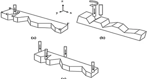
In order to eliminate the effect of tool runout, a single-edge geo-metry has been proposed by Fleischer et al. [111] to guarantee perfect adjustment of the micromachining process parameters such as lateral infeed and feed per tooth values. The stability of three different geo-metries depicted inFig. 7has been investigated. Theirfindings revealed a 30% higher stability for the semi-circular geometry (geometry 3 of Fig. 7) when compared to the trapezium-shaped geometries (geometry 1 and 2 ofFig. 7), meaning that due to the smaller deflection of the third geometry, more accurate machining can be achieved.
Oliaei and Karpat [58] also designed a single-edge cutting tool for micromachining of titanium alloy as depicted inFig. 8. They exploited WEDM to fabricate micro tools with controlled surface and edge radius values and to promote built-up edge formation. In their study, the protective effect of built up edge (BUE) has been explored during micro machining of Ti6Al4V titanium alloy.
It can be seen that, the publications in thefield of micro tool design Fig. 2. Straight edge micro end mill designed by Cheng et al. [48]. (1) Bottom cutting edge; (2) Side cutting edge; (3) Axial rake face; (4) Radial rake face; (5) Axial clearance face; (6) Radial clearance face (with the kind permission from Springer).
Fig. 3. Micro end mills with various geometries : (a) Two-flute micro end-mill, (b) triangular shaped micro end mill with a tapered body and (c) D-shaped micro end mill with a tapered body [108]. (with the kind permission from iopscience).
Fig. 4. (a) Conventional, (b) Optimized micro-end mills [89] (with the kind permission from Elsevier).
are focused on different issues. Uhlmann and Schauer [89] have been concentrated on the bending stresses and optimization of tool geometry in terms of under neck length and diameter; Li et al. [107] have been focused on cutting tool cross-section optimization and tool wear, Oliaei and Karpat [58] have been focused on tool runout elimination and built-up edge (BUE) promotion. The work of Fang et al. [108] addresses stiffness issues and ease of manufacturing, while the work of Fleischer
[111] devoted to the elimination of tool runout.Table 2provides brief summary of the work reported in the literature. It can be seen that, there is no systematic approach for designing micro-cutting tools. Hence, it is essential to develop a systematic approach for micro cutting tool design which takes into account various aspects and challenges concerning micro tools. It seems that, tailoring micro-end mills based on the requirements of particular machining operations in terms of Fig. 5. (a) Maximum principal stresses on twoflute commercial micro end mill predicted by FEM, (b) Broken micro end mill and its measurement [18].
workpiece material properties, machining strategies and part dimen-sional and surface quality requirements will be a necessary step for designing novel micro cutting tools in the future. Table 2shows the summary of the literature done in this area.
5. Fabrication techniques
Micro tool fabrication is the most important part of realization of micro tools for micromachining applications. Successful fabrication demands for a thorough understanding of design requirements and specifications such as tool diameter, cutting edge radius, number of edges, tool geometric specifications (rake and clearance angle) and tool materials along with the capabilities, characteristics, advantages and limitations of different fabrication techniques. In the selection of fab-rication method for mass scale used, in addition to design requirements, the reliability and economic feasibility of the process need also to be considered, however for the sake of research novelty, cost aspect can be ignored. The subsequent sections are devoted to the various fabrication techniques which are used for the realization of micro cutting tools. These fabrication technologies include, EDM, Focused Ion beam
machining, Laser machining, Mechanical machining, Hybrid ma-chining.
5.1. EDM-based techniques
Electro discharge machining uses electro-thermal energy to remove material and experiences no cutting force due to its noncontact nature. It has the advantages of removing material regardless of material hardness. Therefore, EDM has been a preferred fabrication technique for difficult-to-machine materials since its invention. Non-contact nature of the process also gives extra advantages when it comes to the fabrication of downscaled tool. During EDM; voltage is applied to the gap between electrode and workpiece, depending on the gap distance, electricfield breaks down the dielectric properties of the oil and series of sparks start moving as plasma between the electrodes. The tem-perature of the plasma can go as high up to 10,000 °C which melts the materials from both electrode and results in the formation of crater on both electrodes. Dielectricflush helps removing this debris from the machined area and starts preparing for the next cycle during the spark off time.
Ravi et al. [113] was thefirst to propose block EDM method to fabricate symmetrical electrodes for the application of array of different shape micro holes. As per this method, a piece of rectangular metal block is used along with indexing facility to fabricate electrode. For fabrication of square electrode, the cylindrical tool electrode is fed against the block along z axis and change the orientation of the tool to 90° using indexing attachment. This change of orientation will repeat three times tofinish the four faces of square tool. Using similar method, triangular tool is produced (120° orientation of tool) with tool rotation. Since this method uses multi-pass machining strategies to remove Fig. 6. (a) Commercial micro end mill, (b) newly designed two-flute micro end mill, (c) newly designed four-flute micro end mill [107] (with the kind permission from Springer).
Fig. 7. FE simulation of different micro cutting tool geometries designed by Fleischer et al. [36]. (With the kind permission from Springer).
material, it is especially suitable for fabrication of microscale electrodes of few tens of micron. In addition, proposed method also reduces the chances of electrode breakage.
Perveen et al. [114] designed and fabricated special block (Fig. 10) containing three V slots using wire EDM for fabrication of different shape tool. Mikrotool multipurpose machine facilitated both wire EDM and block EDM set up in the same machine. The use of different edge and orientation of this specially designed block made it possible to fabricate circular, D- shaped, triangular, tapered and square shape tool as shown inFig. 9. This method eliminated the indexing attachment used by Ravi et al. Examples of fabricated tools are presented in the Fig. 10. Perveen et al. [115] also studied tool wear associated with these fabricated tools. Their study used acoustic emission signal to monitor tool condition in order to decide tool dressing requirement. This kind of micro tool, loses their shape and therefore become unfit to continue machining process well before it reaches to its end of life. Dimensional variation in the machined part acts as an indication for stop using the tool for further machining.
Oliaei et al. [58] reported on the fabrication of PCD planarization tool with pyramid pattern using micro WEDM (30μm tungsten wire). Fig. 11presents the fabrication technique and the fabricated tool. Ex-tremely low discharge energy was used during the fabrication, which facilitated lower surface roughness of 120 nm. This fabricated PCD tool was exploited successfully later on for ductile mode silicon grinding to remove subsurface damage originating from earlier machining.
Masuzawa et al. [116] proposed the principle of wire electro
discharge grinding (WEDG) (Fig. 12a). The advantages offered by this process are possible geometric modification and miniaturization of the tools. As this process uses a moving wire (diameter of 50–200 μm), the machined area is always exposed to fresh wire which reduces the effect of wear during machining. Fleischer et al. [117] implemented this principle and fabricated the end mills (Fig. 12b) using brass wire of 100μm with the travel speed of 15 mm/min. Using NC coding, initially the bottom of the milling tool was reduced, following that diameter of the end mill was reduced from 0.3 mm to 0.1 mm. Next step was to machine to reach d-shape end mill. Finally, the clearance angle of 10° was machined at the end of milling tool. Average surface roughness of 60 nm was obtained using machining process parameters of 80 V and stray capacitance. Morgan et al. [118] also fabricated cylindrical PCD tool using similar technique for glass machining. Dong-Yea Sheu et al. [119] proposed twin-wire EDM system where resistance capacitance circuit is combined with Transistor electro discharge circuit for facil-itating rough andfinish machining simultaneously using same machine. With this new EDM system, precise micro-tool can be fabricated which also reduces fabrication time two third of conventional WEDM. On another study, Kim et al. [29] fabricated array of WC electrode using reverse EDM techniques. These array of electrode is useful in fabrica-tion of micro holes array or micro-structure using micro-ECM techni-ques which does not suffer much from tool wear aspect, thus increasing the efficiency. Yamazaki et al. [120] also proposed another simple EDM technique to fabricate micro-tool using self-drilled hole (as shown in the Fig. 13). Micro-rod with negative polarity is used to fabricate hole using Table 2
Summary of micro-tool design.
Tool design Optimization target Techniques used Results
Cheng et al. [49], micro end mill with straight cutting edges
Stiffens, rake angles Static & dynamicfinite element analysis
Small rake angle causes increased stiffness and reduced tool wear, negative rake angle improves strength of cutting edge
Fang et al. [108], commercial two flute, triangular, D- shaped tool
Tool failure mode & improved tool life
Finite element analysis Twoflute tool is 8 times weaker than tapered triangular tool and 12 times weaker than tapered D shaped tool. D shaped tool experience accelerated tool wear due to zero clearance angle.
Uhlmann and Schauer [89], micro-end mill
Innovative tool design with optimized under neck length and diameter
Finite element analysis 30% reduction in bending stress,10% increase in tool life
Oliaei & Karpat [18], commercial two flute micro end mill
Tool deflection and failure Finite element analysis Experimental observation of failure matches FEM results Li et al. [107], commercial micro end
mills
Stiffness & strength Analytical modeling & Finite element analysis
Larger neck angle, negative rake angle and optimized tool core geometry assist in better stiffens
Fleischer et al. [111] Tool runout Finite element analysis Single edge geometry tool assists in proper adjustment of lateral infeed as well as feed per tooth
Oliaei & Karpat, [112], Single edge cutting tool
Promote built up edge formation Tool design & experimental analysis
Micro tool with controlled surface and edge radius promotes built up edge formation during Ti alloy micro machining
Fig. 9. Schematic diagram: (a)Fabrication of PCD triangular micro tool using a dedicatedfixture, (b) Tapered micro tool fabrication using a dedicated fixture at different orientation, and (c) The orientation of the fixture for fabricating D-shaped and square micro tool [114] (with the kind permission from Springer).
micro EDM. In the second step, same tool with reversed polarity is off centered and fed downward inside the hole to create straight rod electrode without causing wear in hole outlet but the inlet. This new technique offers advantage of not requiring the adjustment of initial point over other conventional method thus increases machining effi-ciency.
According to Oliaei et al. [58] the relative motion of the workpiece (micro tool) with respect to the wire electrode is quite challenging when using WEDG process to fabricate micro ball end mills. This is
mainly because the wire diameter and tool size are of the same orders of magnitude, consequently the wire curvature can cause some in-accuracies in the fabricated ball end mill geometries. In an attempt to compensate for wire curvature, Oliaei et al. [58] modified the tool trajectory to produce micro ball end mills. Their results showed that by the developed trajectory, accurate micro ball end mills can be produced by WEDG process. The same issue with WEDG has also been reported by Masaki et al. [121]. They mentioned that the fabrication of precision spherical tool for using micro shape grinding requires high precision, Fig. 10. (a) Circular micro tool, (b) triangular micro tool, (c) square micro tool, (d)D-shaped micro tool, (e) tapered micro tool of 60°, and (f) tapered micro tool of 90° [114] (with the kind permission from Springer).
and it is extremely difficult when using WEDG process. They used a precise tungsten carbide pin gauge (precise diameter and straightness) as a sacrificial electrode to form spherical shaped PCD tools. In this process, a rotating PCD blank follows a cylindrical shape machining path along the pin gauge in order to fabricate spherical PCD tool.
In another study by Oliaei et al. [122], micro end mills of various geometries are being fabricated by a multi-processing approach which combines block-EDM and WEDG techniques (Fig. 14). They studied the effect of EDM input parameters on material removal rate (MRR) and surface roughness. Their fabricated micro end mills have been suc-cessfully used for micromachining of fused silica and silicon.
The possibility of applying micro wire electro-discharge machining (μ-WEDM) to fabricate dual helix cutting tools has been studied theo-retically by Cheng et al. [123]. To do so, they built a mathematical model between tool and wire. As a result of their mathematical ana-lysis, they came into a conclusion that for fabricating such complex geometries six axes machines are necessary. The graphical representa-tion of their simularepresenta-tion is illustrated inFig. 15. Although their proposed solution and six axis machine tool configurations seem to be promising and shows a great potential for fabrication of micro tools with complex geometries, their concept has not yet been experimentally verified. An accuracy analysis method has been proposed by Cheng et al. [124] in Fig. 11. (a) Tool Fabrication steps (b) Fine patterned planarization tool [58] (with the kind permission from Elsevier).
the fabrication of superfinish ball end mills (SFBs) and micro ball end mill with uniform rake angles in axial cross-section (URB) by kinematic modeling and analysis of WEDM process. The results of their kinematic analysis revealed that SFBs cannot be realized since they require a
simultaneousfive-axis CNC WEDM machine tool for their fabrication, while URBs has been fabricated by a simultaneous three-axis CNC WEDM machine. Their fabrication accuracy analysis showed that higher geometrical accuracies can be achieved by appropriate design of Fig. 12. (a) Principle of WEDG. [116] (b) WEDG Machined 100μm Tungsten carbide End mills [117](with the kind permission from Elsevier).
micro cutting tool geometries and by arranging the corresponding fabrication procedures accordingly.
Recently Oliaei and Karpat [125] designed a polycrystalline dia-mond micro end mill with a hexagonal geometry having a parallelo-gram shape featuring a large negative rake angle on the bottom of the tool. The micro end mill has been fabricated by WEDM process and used for micromachining of single crystal silicon. With their proposed geometry (Fig. 16) a fourfold increase in critical depth of cut has been achieved. They also used the same approach [51] to design and fabri-cate a PCD mechanical planarization tool capable of ductile-mode machining of silicon as depicted inFig. 16(c). In their study, in order to decrease the area between the tool and the work material without in-troducing a negative rake angle, some changes have been made. Firstly, the number of edges are increased which, decreases the contact be-tween the tool periphery and the workpiece. In addition, the profile of the slots between edges is modified so that a V-shaped channel is pro-duced. This modification further decreases the surface area between the tool and the workpiece at the bottom of the tool.
As an improvement of WEDM method, Yao Sun et al. [126] pro-posed low speed wire electrical discharge turning (LS-WEDT) along with multiple cutting strategies for fabrication of micro-tools. Principle of LS-WEDT is explained in the Fig. 17 with respect to LS-WEDM method. Authors reported successful fabrication of D-shaped as well as spiral micro tools using proposed method which offers better geometric accuracy compared to WEDG due to non-existence of wire deflection as a result of gravity.
A single edge 0.2 mm in diameter PCD micro end mill has been designed and fabricated by Nakamoto et al. [127] using a custom-made 6-axis WEDM machine as shown inFig. 18and has been used for micro milling of tungsten carbide. A preconditioning has been performed after certain machining period and is shown to have a significant role in
improving surface quality. Their results revealed that after certain amount of machining the machining mode has been changed from milling to micro grinding due to the creation of wear lands on the cutting tool. Tool wear is shown to have no detrimental effect on sur-face quality.
A three step multi-processing approach which combines WEDM, WEDG andμ-EDM processes has been used by Morgan et al. [128] to fabricate micro end mills from PCD (Fig. 19(b) & (c)), which are used to machine grooves in soda-lime glass and pockets in ultra-low expansion (ULE) glass. The WEDM process is used to cut tool blanks of 1 mm in diameter from PCD blanks. The diameter of tool blanks is reduced to about 50μm using WEDG process followed by μ-EDM using a sacrificial block electrode to improve the geometric accuracy of the cutting sur-face. PCD micro tools are shown to produce a surface roughness of 0.3 nm and aflatness of 1.5 μm over a length of 500 μm.
Gao et al. [129] have tried to optimize WEDM process parameters for rough andfinish cutting of PCDs. For rough cutting peak current and voltage pulse width are found to be the dominant WEDM process parameters while forfinishing operation the peak current and peak voltage are shown to be the most important parameters affecting the machining speed. Using optimum parameters, they fabricated a quad-rilateral PCD micro milling tool as depicted inFig. 19. Although the authors didn’t report the diameter of the fabricated micro cutting tool, however they reported a cutting edge radius of 6.7μm. EDM fabrication summary are provided inTable 3.
5.2. Focused ion-beam machining
Focused Ion beam machining (FIB) as a Micro/Nanofabrication process which uses accelerated ions to remove surface atoms of the workpiece [146] which can be used for micro-tool fabrication. It can be Fig. 14. Fabrication of ball end mills and Lollipop end mill by Oliaei et al. [122].
considered as a compound platform with ion beam of tens of nanometer in diameter as a cutting tool and an imaging microscope with a nan-ometer resolution for positioning. In a study conducted by Adams et al. [95], focused gallium ion beam is implemented to fabricate micro cutting tools with a diameter of 25μm having different cutting edge numbers of 2, 4 and 5 cutting edges on micro grain tungsten carbide. They managed to obtain very sharp cutting edges with an edge radius of 0.1μm. Vasile et al. [147], also used FIB to produce micro end mills of 25μm diameter using high speed tool steel. Examples of micro end mills produced by FIB are shown inFig. 20.
An important advantage associated with FIB process is its ability in producing very sharp cutting edges, with edge radii in the order of nanometer. This edge sharpness can last for a long time when using single crystal diamond, but it can be easily worn out in materials like cemented carbide. On the other hand, in applications requiring very small edge radii, FIB process should be preferred, however creating nanometer scale edge radii in tungsten carbide and similar materials seems to be unfeasible, because of the accelerated wear of the tool at the initial stages of the machining. Although, high resolution and high accuracy can be considered as the main advantages of the FIB process, however, a very low material removal rate is a major limiting factor for FIB, which limits this fabrication process being used only for fabricating micro cutting tools with diameters less than 100μm [95].
5.3. Laser beam machining
In the application of laser for fabricating micro tools, several dis-tinct aspects such as laser parameters (laser power, repetition rate,
A femtosecond pulsed laser has been used as an efficient processing method for micro tool fabrication from binder less polycrystalline dia-mond (BLPCD) by Ogawa et al. [151]. A direct conversion sintering method is used to synthesize BLPCD from graphite at ultra-high pres-sure and temperature without any binder materials [152]. BLPCD has superior mechanical properties when compared to the conventional PCD. Since BLPCD has no conductive binder, EDM-based techniques cannot be used for its processing. Thefindings of Ogawa et al. [151] revealed that, a circularly polarized femtosecond pulse laser is the most proper choice for successful machining of BLPCD. The use of this laser made it possible to obtain an average surface roughness of 0.022μm with an MRR of 0.004 mm3/s. They claimed that almost no graphiti-zation has been observed at the surface. A Q-switched Nd:YAG laser (1064 nm, 100 ns, 70μm spot size) has been used by Everson and Mo-lian [153] in the two-dimensional fabrication of micro tools in a fine-grain PCD. They achieved an MRR of 0.02 mm3/min, kerf (cutting width) of 27μm, and 3 μm top surface edge radius. When a laser beam interacts with PCD material, the diamond can be transformed into amorphous carbon and graphite. Stress break up of diamond intofine particles may also be observed, which is attributed to several factors such as thermal stresses and the phase transition of diamond and cobalt. An IR YVO4 laser (l -1.064 mm) was used by Suzuki et al. [154] to fabricate single crystalline diamond (SCD) micro milling tools having three dimensional cutting edges (Fig. 21(a)). Fabricated milling tools are presented in theFig. 21(b).
Butler et al. [155] exploited ND:YAG Q-switched pulsed laser system along with the indexing rotary stage and fabricated rotary solid grinding wheel made of polycrystalline diamond (Fig. 22). 36 staggered rows of the grinding tool were laser ablated by setting the rotary stage at 10° and with the help of Mastercam X that controls the laser path. Laser parameters used in this fabrication were output power of 100 W, pulse frequency of 50 kHz, lasing wavelength of 1064 nm and focal spot diameter of 40μm [155].
Eberle et al. [156] demonstrated the laser technique to shape single cubo-octahedral shape diamond grains for engineering grinding tools (EGT) application.Fig. 23shows the unmodified and modified diamond grain with the help of laser machining. For this purpose, an Nd:YVO4 diode pumped MOPA laser system with pulse duration of 10 ps is used. As can be seen fromFig. 23, both clearance and rake angle are fabri-cated in a single diamond grain which reduces the volume of the grain to 50%. Eberle et al. [157] also fabricated drill bit of 150μm diameter using picosecond laser where the chisel and cutting face are completed in one step. However, this process comes with discretization error such as steps which are quite noticeable from theFig. 24. Finer Z steps size and objectives with higher numerical aperture could be a solution to get rid of this problem.
With the downscaling of tool size, conventional machining no longer offers economical solution for fabrication of micro tools, espe-cially with the cases when the hardness of cutting materials becomes a hindering factor. Thermal machining has the advantages over conven-tional mechanical machining in terms of no cutting force generation. Fig. 16. Micro end mill designed and fabricated by [125], Oliaei and Karpat, (a)
Solid Model; (b) Fabricated micro end mill (c) Mechanical planarization tool [51].
5.4. Mechanical machining
The most predominant mechanical method of micro tool fabrication is the grinding process, which is widely accepted in the industry, however, on some occasions the grinding process is not considered precise enough to fabricate some micro tools with small diameters and complex geometries [11]. This mainly arises from the fact that in the grinding process, there is a direct mechanical contact between grinding wheel and cutting tool. The induced forces exerted to the cutting tool will result in tool deflections which reduces the grinding precision and may result in tool breakage [110]. These deflections together with grinding wheel wear and heat generation will result in some variations in the dimension of the produced micro end mills. The variability in the diameter of 30 up-sharp tools (0.8 mm nominal diameter) selected from same batch are shown by Oliaei [7] as depicted inFig. 25where tool diameters are measured using Keyence VHX-1000 digital microscope (600x magnification). It is worth mentioning that the actual diameter of the micro end mills is generally smaller than the nominal diameter in
order to compensate for possible runout in the tool holder-spindle system. However, there exists a size variation due to the grinding process. Another important issue when using grinding for micro tool fabrication is subsurface damages caused by grinding, which lowers the strength of the end mills fabricated by this method [110]. This issue has also been emphasized by Aoki and Takahashi [158], where they used grinding process to fabricate 25μm diameter simple oblique-cut mill (SOC mill) from tungsten carbide.
It is shown by Schaller et al. [159] that up to 50% of the micro cutting tools (50μm diameter, back angle approximately 6°, tip clear-ance of approximately 6°, and radial clearclear-ance of 5–10 μm) made up of tungsten carbide (ISO-K10) with a grain size of 1–2 μm, were broken during grinding using WINTER diamond grinding wheels (resin-bonded, grade D126/D54/D15). This quite high scrap rate has a sig-nificant influence on the cost of micro end mills produced by grinding process. Therefore, as it has been suggested by Huo et al. [11] taking into consideration the probability of micro tool edge fracture and other grinding defects such as large heat affected zone and grinding burns, Fig. 17. The schematic diagram of(a) LS-WEDT method and (b)LS-WEDM (c) Fabricated D shaped tool [126].
reliable micro tool supplier should be carefully selected. It is highly recommended to select carbide micro tools withfiner grain size and to use microscopes with high magnifications to inspect the cutting edge geometry. The reason for the selection of smaller grain size is the
increased fracture toughness atfiner grain sizes.
Due to the problems arising from mechanical contact during micro tool fabrication, the major concern is to reduce machining forces [160]. In an attempt to reduce grinding forces Onikura et al. [160] efficiently Fig. 19. (a) A quadrilateral PCD micro milling tool designed and fabricated by Gao et al. [129].
Table 3 Summary of tool fabrication using EDM techniques. Type of EDM Fabricated Micro-tool Material Dimension of the tool Application Remarks WEDG Tungsten carbide Cylindrical & semi cylindrical tool Micro-ECM with ultrasonic vibration to create micro holes Semi-cylindrical micro-tool off ers higher machining rate as well as precision [ 130 ] Wire EDM Ultra-fi ne WC 21 by 21 microns square electrode array Batch micro-holes on nebulizer upward batch micro EDM provides better machining time than downward one due to better debris removal [ 131 ] Micro-WEDM plus WEDG WC 100 microns Proposed surface roughness prediction model for the fabricated tool [ 132 ] Micro EDM with sacri fi cial block, rotating disk, guided running wire 99.9% W (Ø0.2 –0.5 mm) High aspect ratio micro tools Surface Engraving on Al alloy Rotating disk off ers best performance [ 133 ] Micro-EDM with RC & transistor type isopulse generator Tungsten 20-40 microns Transistor type along with servo control off ers 24 times material removal compared to RC type [ 134 ] Micro-EDM with inchworm feeding system Red copper 25 microns micro holes and micro structures on stainless steel & single crystalline silicon [ 135 ] tool aspect ratio of 20 can be achieved due to high accuracy of tool feeding as well as quick response for gap maintenance Micro-EDM Tungsten, cemented tungsten, cemented tungsten carbide made of super fi ne particles (SWC) 2.8-4 microns SWC with 2.8 micron diameter was achieved [ 136 ] tangential feed WEDG Tungsten 27 microns electrodes Array of Micro holes fabrication Electrode fabrication accuracy less than 2 micron and hole fabrication accuracy ± 1.1 μ m[ 137 ] Twin-wire EDM system, combining TrC and RC electro-discharge pulse generators WC 0.02 mm micro-electrodes Machining time can be reduced upto 6 times of conventional machining [ 138 ] WEDG Tungsten fabricated tool electrodes: cylindrical, conical, spherical, and bolt-shaped(below 60 micron diameter EDM micro-grooving on stainless steel high voltage and a small condenser capacitance is recommended to reduce tool wear [ 139 ] WEDG cemented carbide 6 microns tool Micro-hole of 6.7 μ m diameter a Higher feed rate can cause tool breakage [ 140 ] WEDG Tungsten carbide 31 micron tool Micro-slot and micro thin-walled structure on Al alloy Burr formation, can be prevented by minimum the axial engagement and the feed [ 141 ] μ -WEDM P type silicon wafer High aspect ratio Silicon micro electrode 5 mm long 120 μ m by 120 μ m electrode 5-8 μ m recast layer removal by etching results in machined surface without cracks and electrode shape remains same [ 142 ]. WEDG WC, Titanium series-pattern micro-disk with thickness of 10 μ m Micro-slit with the width of less than 10 μ m. Grain size of tool material aff ect the minimum thickness of fabricate tool due to internal stress state [ 143 ]. Turning-μ EDM ’ hybrid process and the ‘moving-electrode-block-μ EDM ’ process Brass and CuW Ø: 70 mm, length: 3 mm high-aspect-ratio micro-holes Vibration-assisted micro-EDM was found to provide higher-aspect-ratio micro-holes compared to those without vibration [ 144 ] Reverse electrical discharge machining WC rod Multiple-tipped micro electrodes. 35 μ mi n diameter Array of microholes Micro-ECM is used for array of micro holes fabrication which su ff ers literally very low tool wear [ 120 ] wire-EDM WC Multiple electrodes cross-section of 100 m and are 5 mm long. Micro-slots [ 145 ]
Fig. 20. Examples of micro tools fabricated by FIB process: (a) Xu et al. [77], (b) Wu et al. [146], (with the kind permission from Springer) (c) Picard et al. [148], (with the kind permission from Elsevier) (d) Adams et al. [95]. (With the kind permission from Elsevier).
used ultrasonic vibration grinding (75 kHz-0.5μm), to fabricate micro cutting tools with diameters less than 100μm and aspect ratios in the range of 3 to 18. They came into a conclusion that by applying ultra-sonic vibrations, it is possible to achieve a 10–20% reduction in the diameter of micro tools and to increase aspect ratio about 50%. These improvements were mainly due to the reduced grinding forces upon applying ultrasonic vibrations. A grinding system equipped with
super-fine abrasive wheels is developed by Ohmori et al. [161] and is used to fabricate ultra-fine micro cutting tools with various geometries as de-picted inFig. 26. Profilometer with resolution of 0.1 μm installed on the machine assists in measuring tool diameter during machining process without taking off the tool from the machine. Therefore, tool with in-itial diameter of few hundred micrometers can be reduced tofinal tool with several micrometers of diameter.
Fig. 22. Unused laser ablated solid diamond micro-grinding tool [155]. (with the kind permission from Elsevier).
Fig. 23. Diamond grain shaped by laser for EGT applications [156] (with the kind permission from Springer).
Aurich et al. [162] made use of the process kinematics of grinding and fabricated customized end geometry micro-end mills. 10μm and 20μm tool made of tungsten are fabricated using a desktop 3-axis tool grinding machine having two grinding spindles (pre grinding orfine) as shown in theFig. 27. The details of the fabricated tools can be seen in Fig. 28. Small cutting edge radius and specific geometry tools facilitate the easy chip formation as well as low cutting force. This fabrication process also has the potential to fabricate tools with different helix angle as well as other shapes like dovetail profile or ball end mills. Liang et al. [163] have used a six axis CNC grinding machine to produce micro conical surface ball-end mills (CSBM) with 500μm diameter and normal rake and relief angle of 10° and 20°, respectively. In their study, the kinematic principle of the six axis CNC grinding machine has been used to realize micro ball end mills with a diameter error of about 0.26%. CSBMs are used to produce micro dimples on hardened die steel H13. When machining with CSBMs, more stable radial milling forces, stable micro dimple roundness error and improved wear resistance have been observed compared to spiral blade ball-end mills (SBBM). These improvements reveal that by modifying some features of the conven-tional micro end mills, their performance can be improved significantly. 5.5. Hybrid and multi-process fabrication techniques
There are some limitations associated with traditional machining in terms of micro scale fabrication of tools. The tool life span has been reduced significantly due to the thermal stresses and deformations, and degenerative layer on the fabricated tools associated with this process. Therefore, some hybrid techniques have been proposed to fabricate micro tool. Fabrication of miniature grinding tool from diamond for precision grinding of micro-structure was proposed by Chen et al. [164]. WEDG along with micro-EDM was used to fabricate tungsten tool substrate of 100-20μm external diameter and then Ni(binder), Diamond (cutting edge) were co-deposited on the substrate using
Fig. 25. The measured diameter of 30 up-sharp micro end mills [7].
Fig. 26. Micro end mills fabricated by grinding process [161] : (a) Ultra-fine micro end mill, (b) Hexagonal micro-tool. (with the kind permission from Elsevier). Fig. 27. Schematic representation of the tool fabrication process [162] (with the kind permission from Elsevier).
Fig. 28. Micro end mill D = 10μm and D = 20 μm [162]. (with the kind per-mission from Elsevier).
electroform technique (Fig. 29). In order to facilitate better deposition of diamond grain, Chen et al. [164] also designed miniature funnel mould. The substrate is placed in the funnel mould which also works as a cathode. Inner tapered hole of funnel helps deposition of increased amount of diamond as itflows from top to down. As a result, probability of diamond deposition on the substrate increases. Moreover, this funnel has the added advantage of separating the unnecessary current from the high current density region which helps reducing effect of point on the cathode. Application of such array of funnel can facilitate the fabrica-tion of several different micro tools with increased efficiency.
Fabricated tool after combined WEDG and micro-EDM plus co-de-position are presented in theFig.30[164]. Suzuki et al. [165] devel-oped a micro end mill from PCD for ductile mode machining of ceramic micro aspheric molds and dies. In their study, combined WEDM and diamond grinding technique is used to fabricate micro end mills. WEDM helps to fabricate the cylindrical plain tool from PCD wafer. A multi-tooth PCD milling tool with twenty cutting edges which are ob-tained by grinding and polishing using diamond wheels and loose abrasives on a PCD rod having the grain size of 0.5μm being produced as depicted in Fig. 31.Table 4 provides summary of multi-process techniques for tool fabrication.
6. Summary
Application of miniaturized products and parts in different in-dustries clearly is pushing the manufacturers towards conducting re-search in thefield of micro fabrication and to adopt newer technologies. This growing field is demanding the change of machine tool tech-nology, metrology, fabrication, cutting tool and coating technologies, since factors such as cutting edge radius, tool run out, material homo-geneity at microscopic scale and microscopic defects which are quite negligible at macro-scale are gaining crucial importance in micro-scale. Taking these issues into account this review paper discusses the chal-lenges faced in the micro cutting tool technology which is a major Fig. 29. (a)Miniature funnel mould(b) Array of mould [164] (with the kind permission from iopscience).
Fig. 30. a) Tungsten substrate after wire EDG & micro EDM (b) micro tool after co-deposition [164]. (with the kind permission from iopscience).
Fig. 31. (a) The process of fabricating micro-milling tool from PCD (b)SEM image of multi-teeth PCD micro-milling tool and its cutting edges [165] (with the kind permission from Elsevier).
limitations) and application phase (precise clamping, run out and de-flection compensation, etc.).
This review paper clearly demonstrated the lack of a systematic approach for designing micro cutting tools. Therefore, before making decision about fabrication technique, micro tool design aspects need to be considered carefully in the design phase in order to deal with tool wear, stiffness, strength, tool run out and the interaction between micro cutting tool and workpiece material. As proposed by different re-searchers, different part of the micro tool such as, rake angle, edge number, under neck length, diameter can be designed to optimize all these criteria. To do so, the development of analytical and numerical models capable of prediction tool wear, breakage and stiffness in con-junction with micromachining process models is essential. Furthermore, there is a need for a database of material properties such as fracture toughness, elastic modulus, thermal conductivity, thermal expansion, etc. for different tool materials based on grain size, binder and their processing information. Apart from tool geometry design, researchers also reported on the potential of tool coating in order to achieve improved tool life and better tool performances. However, conventional coating technology may not be successfully applied for micro scale tool coating due to the fact that microscale defect which was not an issue for macroscale tool can be detrimental for microscale tool performance. According to the literature, coating technology such as CVD, hotfilament CVD reactive closed field unbalanced magnetron sputtering ion plating, combined sputtering and arc ion plating (hybrid coating system) are successfully exploited for microscale tool coating, however general guidelines for the selection of appropriate coating type based on workpiece material properties have not established yet. This is demanding for more researches about the effect of coating on the per-formance of micro cutting tools during machining of different en-gineering materials. Additionally, there are many publications in the literature without reporting coating specifications. Therefore, the re-search community should be encouraged to provide the coating speci-fications to make it possible to establish a general guideline for the selection of suitable coating based on the requirements of micro-machining task.
It can be seen that, while grinding is the most extensively used process for micro tool fabrication in the industry, the research com-munity has been well benefited from non-traditional machining pro-cesses for this purpose. Among non-traditional methods, EDM-based techniques seem to be the most widely used processes of micro tool fabrication due to its versatile nature as long as hardness concerns. The presence of recast layer, over-burn, larger cutting edge radius and tool wear can be named as the limitations of EDM-based techniques which need further investigations. Comparing FIB and EDM-based techniques, it can be found that FIB is noticeably more costly and slower than EDM-based techniques, however it is capable of producing very sharp edges. The very sharp edge (small edge radius) generated by FIB in materials such as WC and PCD can be easily chipped at the initial stage of the cutting process or it can be rounded and transformed into larger radii with the continuation of micro machining operations. Therefore, there is a need for using stronger materials wherever sharp edges are a sig-nificant requirement. On the other hand, laser fabrication of micro tools
Table 4 Summary of tool fabrication using hybrid & Multi-process techniques. Type of process combination Fabricated Micro-tool Material Dimension of the tool Application Remarks BEDG process & micro Turning PCD insert 11 μ m in diameter Micro holes, 3D micro-features [ 166 ] Micro Turning micro EDM hybrid process CuW, Brass 45-19.3 μ m Micro holes machining [ 144 ] LIGA & micro -EDM WC-Co Below 200 μ m Micro –mechanical component and micro processing tool [ 167 ] Vibration assisted micro EDM Ag-W 50 μ mb y5 0 μ m square shaft Signi fi cant reduction of machining time. perpendicular machining time than the parallel vibration WEDM and ECM tungsten 0.3 μ m diameter 1 μ m diameter Holes drilled in brass 0.5 μ m diameter holes in silicon is smallest
![Fig. 1. Droplets and defects at the surface and edges of the micro end mills after PVD coating [68].](https://thumb-eu.123doks.com/thumbv2/9libnet/5877363.121222/3.892.63.425.808.1075/fig-droplets-defects-surface-edges-micro-mills-coating.webp)
![Fig. 3. Micro end mills with various geometries : (a) Two-flute micro end-mill, (b) triangular shaped micro end mill with a tapered body and (c) D-shaped micro end mill with a tapered body [108]](https://thumb-eu.123doks.com/thumbv2/9libnet/5877363.121222/5.892.214.680.85.405/micro-various-geometries-flute-triangular-shaped-tapered-tapered.webp)

![Fig. 15. Simulation of micro-tool fabrication by micro-wire EDM process [36] [123] with the kind permission from Springer).](https://thumb-eu.123doks.com/thumbv2/9libnet/5877363.121222/12.892.122.793.87.221/fig-simulation-micro-fabrication-micro-process-permission-springer.webp)
![Fig. 16. Micro end mill designed and fabricated by [125], Oliaei and Karpat, (a) Solid Model; (b) Fabricated micro end mill (c) Mechanical planarization tool [51].](https://thumb-eu.123doks.com/thumbv2/9libnet/5877363.121222/13.892.71.421.80.609/micro-designed-fabricated-oliaei-karpat-fabricated-mechanical-planarization.webp)
![Fig. 18. Custom designed single edge PCD micro end mill by Nakamoto et al. [127].](https://thumb-eu.123doks.com/thumbv2/9libnet/5877363.121222/14.892.181.717.90.552/fig-custom-designed-single-edge-pcd-micro-nakamoto.webp)
![Fig. 20. Examples of micro tools fabricated by FIB process: (a) Xu et al. [77], (b) Wu et al](https://thumb-eu.123doks.com/thumbv2/9libnet/5877363.121222/17.892.182.714.84.400/fig-examples-micro-tools-fabricated-fib-process-xu.webp)
![Fig. 22. Unused laser ablated solid diamond micro-grinding tool [155]. (with the kind permission from Elsevier).](https://thumb-eu.123doks.com/thumbv2/9libnet/5877363.121222/18.892.190.706.82.414/unused-laser-ablated-solid-diamond-grinding-permission-elsevier.webp)
![Fig. 27. Schematic representation of the tool fabrication process [162] (with the kind permission from Elsevier).](https://thumb-eu.123doks.com/thumbv2/9libnet/5877363.121222/19.892.467.827.357.794/fig-schematic-representation-tool-fabrication-process-permission-elsevier.webp)
