r⫽ 4.7. In a future study, we plan to fabricate the designed filter on substrates of Al2O3 or ceramic materials in order to obtain superior frequency performance, and then integrate the filter with other active/passive circuits on a chip [7].
4. CONCLUSION
A novel dual-mode bandpass filter using a microstrip triangular ring resonator with coupling stubs has been proposed. Quasi-L-shaped I/O arms used as coupling stubs for enhanced coupling are nonorthogonally and symmetrically separated on each corner of triangular resonator in order to specify the locations of the trans-mission zeros and improve the upper stopband. The perturbation element is introduced within the resonator at a symmetrical loca-tion in order to affect the passband characteristics. New filters having narrower or wider bandwidth and transmission zeros can be designed by tuning the length of the coupling stubs and the size of the perturbation element.
REFERENCES
1. I. Wolff, Micro-strip band-pass filter using degenerate modes of a micro-strip ring resonator, Electron Lett 8 (1972), 302–303.
2. L. Zhu, P.M. Wecowski, and K. Wu, New planar dual-mode band-pass filter using cross-slotted patch resonator for simultaneous size and loss reduction, IEEE Trans Microwave Theory Tech 47 (1999), 650 – 654. 3. M. Matsuo, H. Yabuki, and M. Makimoto, Dual-mode
stepped-imped-ance ring resonator for band-pass filter applications, IEEE Trans Mi-crowave Theory Tech 49 (2001), 1235–1240.
4. K.K.M. Cheng, Design of dual-mode ring resonators with transmission zeros, Electron Lett 33 (1997), 1392–1393.
5. L.H. Hsieh and K. Chang, Dual-mode quasi-elliptic-function band-pass filters using ring resonators with enhanced-coupling tuning stubs, IEEE Trans Microwave Theory Tech 50 (2002), 1340 –1350.
6. L.H. Hsieh and K. Chang, Compact dual-mode elliptic-function band-pass filter using a single ring resonator with one coupling gap, Electron Lett 36 (2000), 1621–1622.
7. U. Karacaoglu, I.D. Robertson, and M. Guglielmi, A dual-mode mi-crostrip ring resonator filter with active devices for loss compensation, IEEE MTT-S 1 (1993), 189 –192.
© 2004 Wiley Periodicals, Inc.
LENS OR RESONATOR?
ELECTROMAGNETIC BEHAVIOR OF AN
EXTENDED HEMIELLIPTIC LENS FOR A
SUB-MILLIMETER-WAVE RECEIVER
Artem V. Boriskin,1,3Alexander I. Nosich,1,2
Svetlana V. Boriskina,2Trevor M. Benson,2
Phillip Sewell,2and Ayhan Altintas3
1Department of Computational Electromagnetics
Institute of Radio-Physics and Electronics National Academy of Sciences
Kharkov 61085, Ukraine
2George Green Institute for Electromagnetics Research
University of Nottingham Nottingham NG7 2RD, UK
3Department of Electrical and Electronics Engineering
Bilkent University 06533 Ankara, Turkey
Received 24 May 2004
ABSTRACT: The behavior of a 2D model of an extended hemielliptic
silicon lens of a size typical for THz applications is accurately studied for the case of a plane E-wave illumination. The full-wave analysis of the scattering problem is based on the Muller’s boundary integral-equa-tions (MBIE) that are uniquely solvable. A Galerkin discretization scheme with a trigonometric basis leads to a very efficient numerical algorithm. The numerical results related to the focusability of the lens versus its rear-side extension and the angle of the plane-wave incidence, as well as near-field profiles, demonstrate strong resonances. Such effects can change the principles of optimal design of lens-based re-ceivers. © 2004 Wiley Periodicals, Inc. Microwave Opt Technol Lett
43: 515–518, 2004; Published online in Wiley InterScience (www. interscience.wiley.com). DOI 10.1002/mop.20520
Key words: dielectric lens; focusability; boundary integral equations
1. INTRODUCTION
Planar slot or strip elements combined with dielectric lenses are attractive building blocks for millimeter- and sub-millimeter-wave receivers [1–5]. The attention they have been attracting recently is due to their capability for compact integration with other electronic components, such as detecting diodes, local oscillators, and mix-ers. Furthermore, they provide better efficiency than other types of antennas printed on homogeneous substrates. The elliptical shape of the lens is borrowed from optics to provide focusing properties if its eccentricity is selected properly. On the other hand, the lens interface gives rise to reflections inside a realistic lens that may significantly affect the input impedance and sensitivity. This as-pect, which has not been properly investigated in the literature, is a critical point in the overall design of lens antennas [2, 5]. Various analytical techniques used to simulate dielectric lenses have been commonly based on ray tracing and neglecting the lens size and curvature, and hence have failed to characterize the internal reso-nances. The validity of such approximations can be questionable in many cases, as the actual size of the lens is several wavelengths [1– 6]. In fact, the behavior of such a lens should clearly display both raylike and resonance-mode features. On the other hand, FDTD-based solvers are time- and memory-consuming, require accurate treatment of the back-reflections from the edge of the computational window, and may suffer from a loss of accuracy at resonant frequencies. All the above shows that the true electro-magnetic behavior of dielectric lenses is still far from clear.
In this paper, we analyze extended hemielliptic lenses in the receiving mode. If the eccentricity of the ellipse relates to the lens dielectric constant as
Figure 7 Simulated and measured performances of the dual-mode band-pass filter with wider bandwidth (L1⫽ 20 mm, L2⫽ 10.3 mm, L3⫽ 4 mm
W1⫽ 3 mm, W2⫽ 0.5 mm, W3⫽ 5.9 mm G ⫽ 0.2 mm and A ⫽ 60°)
e⫽ 1/
冑
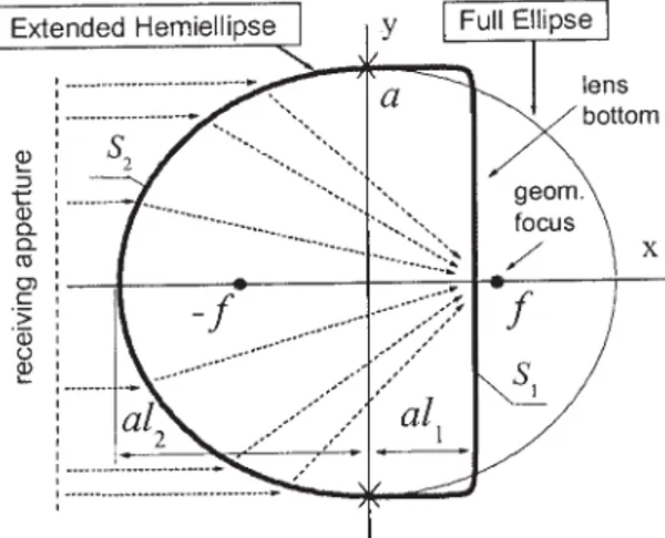
, (1) then geometrical optics (GO) predicts that all the rays of a parallel family that impinge on the front surface of the lens are collected at the rear focal point (Fig. 1). In applications, it is important to know the actual shape of the focal domain for various lens sizes and various angles of incidence of the plane wave.2. OUTLINE OF SOLUTION
A brief outline of the MBIE method is as follows. In two dimen-sions, the studied problem can be formulated as plane-wave scat-tering by a dielectric cylinder with a smooth contour of cross-section, whose frontal part follows Eq. (1). The application of Green’s identity enables one to express the fields inside and outside the lens in terms of the limiting values of the fields and their normal derivatives on the cylinder contour. By applying transmission-type boundary conditions, a set of Fredholm 2nd-kind IEs is obtained, known as Muller’s boundary IEs [7]. These can be discretized using the collocation method [8]. However, we en-hance the convergence of the discretized solutions by applying the Galerkin method with entire-domain angular exponents (also known as trigonometric polynomials) as the expansion functions. To treat the singularities in the Green’s functions and their deriv-atives in the discretization scheme, we use an analytical integration of the canonical circular-cylinder counterpart terms. Such a pro-cedure enables us to exploit the fact that the trigonometric poly-nomials are orthogonal eigen-functions of the canonical-shape operators.
This procedure results in a Fredholm 2nd-kind infinite-matrix equation having favorable features, with the right-hand-part terms and matrix elements obtained as Fourier-expansion coefficients of twice-continuous functions. These can be economically computed using the fast Fourier transform (FFT) and double FFT algorithms, respectively. The algorithm developed guarantees point-wise con-vergence of the numerical solution, that is, the possibility of minimizing the error to machine precision by solving progres-sively larger matrices. Note that this convergence is a universal one—the required accuracy can be achieved for an arbitrary set of lens parameters, for example, for any value of the contrast between the lens material and the background medium. It is also free from the inaccuracies near to the sharp natural resonances that are intrinsic to conventional numerical approximations [9], as well as from the well-known defect of “numerical resonances” occurring if
the fields are derived from single- or double-layer potentials [10]. More details of the algorithm’s properties can be found in [11]. 3. NUMERICAL RESULTS
We shall consider the cross-section of the extended hemielliptic lens bounded by a curve S, which is twice-differentiable at every point and consists of two parts, S1 and S2, smoothly joined together (Fig. 1). Here, S2is one-half of the ellipse whose eccen-tricity is assumed to be in accordance with Eq. (1), and S1 is one-half of a so-called “super-ellipse” that approximates a rectan-gle with rounded corners. Both curves can be characterized by the same equation:
共 x/lja兲2j⫹ 共 y/a兲2j⫽ 1, j ⫽ 1, 2. (2)
In the specific computations presented here, we shall use a silicon lens ( ⫽ 11.7) whose size is approximately three free-space wavelengths (ka⫽ 10); the contour parameters are1⫽ 10 and 2⫽ 1, respectively.
The concentration of the field along the x- and y-axes can be quantified in terms of “focusability,” which is defined as
Fx⫽ aI共 xm, ym兲 兩xm⫺ x0.5兩 , Fy⫽ aI共 xm, ym兲 兩ym⫺ y0.5兩 , (3)
where ( xm, ym) are the coordinates of the maximum field intensity (I ⫽ 兩Ez兩2) inside the lens, and ( x0.5, y0.5) are the coordinates where the field intensity is one-half of the maximum value.
Proceeding from GO, one usually considers that the focusabil-ity of the true elliptic lens is preserved even if one removes its rear part behind the GO focus. For a wavelength-scale lens, this is not true. This claim is supported by Figure 2, which shows the focus-ability of the lens versus its relative bottom-extension parameter, l1. One can see that it increases monotonically with l1approaching and even exceeding the value corresponding to the full ellipse focus location (marked with a dashed line). In Figure 3, one can see the movement of the point with the highest field intensity along the x-axis and the field-intensity peak value versus the same parameter (figures mark the values of l1 at the points indicated with arrows).
Analysis of the graphs shows that there are two mechanisms that explain the internal field enhancement. One is the focusing, which causes a wide peak in the focusability of Figure 2 near to the
Figure 2 Focusability of the extended hemielliptic lens vs. the relative lens extension parameter
Figure 1 Geometry and notations for an extended hemielliptic lens, (foci of the full ellipse are marked with black dots)
value of l1 that corresponds to the GO focus location, l1 ⫽ 0.2924. Another is a series of internal resonances, which results in a sequence of sharp features, in both the focusability and the peak-field intensity. Note that this behavior is not predicted by GO. Another fact that can be of interest for antenna designers is that the position of the highest-intensity spot migrates in a complicated manner between the bottom of the lens and the location of the GO focus (Fig. 3). One can see that the spot approaches the lens bottom if it is either cut near to the GO focus or is cut to exploit an internal resonance (Fig. 4). Note that the peak intensity for the extended hemielliptic lens tuned to an internal resonance (hereafter referred to as a resonant lens) can reach over 300% in comparison to the commonly used lens extended to the GO focus location (hereafter referred to as a quasi-optical lens).
The near-field profiles for the resonant values of l1revealed in Figure 2 are shown in the bottom of Figure 5. These resonances are closely related to the asymptotic GO resonances known as “bounc-ing-ray” or “billiard-type” ones. Here, they have specific triangular profiles and can be classified with two indices, which count the field variations along the lens bottom (m) and a side of the triangle (n). Two neighboring resonances in l1 have n and n⫹ 1 varia-tions, and the distance between them corresponds to half a wave-length in the dielectric along the triangular side.
Therefore, this accurate study has shown that the resonances are very important to understand the behavior of a wavelength-scale lens. Furthermore, replacement of the full ellipse by an
extended hemiellipse leads to a dramatic change in the field distribution inside the lens. Nevertheless, a proper choice of the lens rear-side extension may lead to a considerable improvement in the lens’ ability to produce field spots with large intensity and hence boost receiver sensitivity.
Figure 6 shows the field intensity along the flat side for a quasi-optical lens and a resonant lens tuned to the resonance at l1⫽ 0.471, for several angles of plane wave incidence. It can be seen that the quasi-optical lens has a single spot of high field intensity located at the flat side. If the incidence angle␥ of the plane wave (counted from the x-axis) varies, the main field max-imum moves along the lens flat side and broadens. At␥ ⫽ 20°, the field intensity in the main maximum falls to a half of its value with normal incidence, while the secondary maxima rise to nearly the same level.
In contrast to this, three spots of the same peak intensity are observed for the resonant lens. Each peak is twice as large as that of the quasi-optical lens. As the incidence angle of the plane wave varies, these high-field spots maintain fixed locations and the maximum intensity drops by half if␥ ⫽ 8°, while the side-spot peaks remain at 40% of the peak intensity for normal incidence.
This analysis shows that a silicon lens tuned to an internal resonance has certain advantages, despite losing its wideband nature. Particularly attractive are the stability of the resonant field Figure 3 The x-coordinate and the peak field intensity for the extended
hemielliptic lens vs. the lens extension parameter (characteristic values of
l1are indicated by arrows)
Figure 4 Normalized distance between the peak field-intensity-point
x-coordinate and the lens bottom vs. the lens-extension parameter.
Figure 5 Near-field intensity portraits (8.3% contours) for the full-elliptic and extended hemifull-elliptic silicon lenses with different extensions (dotted lines mark the location of the rear focus of the full ellipse)
with respect to the angle of arrival of incident wave and the fact that several times greater values of the peak intensity can be achieved. Narrowband receivers exploiting these effects may potentially have improved sensitivity and scanning perfor-mances.
4. CONCLUSION
The electromagnetic behavior of an extended hemielliptic lens used in millimeter- and sub-millimeter-wave receivers has been studied in a 2D formulation. An efficient and accurate numerical method based on the MBIE technique has been applied to the solution of the plane wave scattering by a smooth dielectric cyl-inder whose cross-section contour follows the shape of such a lens. Our numerical results have demonstrated effects that cannot be predicted with GO or physical optics approximations. The most important feature revealed by the accurate analysis is that reso-nances may play a dominant role in the wavelength-scale lens behavior. We have also provided particular numerical evidence that advanced characteristics of the lens-coupled receivers can be achieved, although in a narrow band, by exploiting a resonance.
Therefore, the answer to the question put in the title is that a typical THz-lens antenna made of silicon is a dielectric resonator rather than a lens.
ACKNOWLEDGMENTS
This work has been supported by the UK EPSRC under grants no. GR/R65213/01 and no. GR/S60693/01(P) and by the TUBITAK grant no. EEEAG-103E037.
REFERENCES
1. D.F. Filippovich, S.S. Gearhart, and G.M. Rebeiz, Double slot on extended hemispherical and elliptical silicon dielectric lenses, IEEE Trans Microwave Theory Tech 41 (1993), 1738 –1749.
2. P.U. Jepsen and S.R. Keiding, Radiation patterns from lens-coupled terahertz antennas, Optics Lett 20 (1995), 807– 809.
3. A. Neto, S. Maci, and P.J.I. de Maagt, Reflections inside an elliptical dielectric lens antenna, IEE Proc Microwaves Antennas Propagat 145 (1998), 243–247.
4. X. Wu, G.V. Eleftheriades, and T.E. van Deventer-Perkins, Design and characterization of single and multiple-beam mm-wave circularly po-larized substrate lens antennas for wireless communications, IEEE Trans Microwave Theory Tech 49 (2001), 431– 441.
5. J. Rudd and D. Mittleman, Influence of substrate-lens design in tera-hertz time-domain spectroscopy, J Opt Soc Am B 19 (2002), 319 –329. 6. J. Rudd, J.I. Johnson, and D. Mittleman, Quadrupole radiation from
terahertz dipole antennas, Optics Lett 25 (2000), 1556 –1558. 7. C. Muller, Foundations of the mathematical theory of electromagnetic
waves, Springer, Berlin, 1969.
8. V. Rokhlin, Rapid solution of integral equations of scattering theory in 2-D, J Comput Phys 86 (1988), 414 – 439.
9. G.L. Hower et al, Inaccuracies in numerical calculations of scattering near natural frequencies of penetrable objects, IEEE Trans Antennas Propagat 41 (1993), 982–986.
10. S. Amini and S.M. Kirkup, Solutions of Helmholtz equation in the exterior domain by elementary boundary integral methods, J Comput Phys 118 (1995), 208 –221.
11. S.V. Boriskina, T.M. Benson, P. Sewell, and A.I. Nosich, Accurate simulation of 2D optical microcavities with uniquely solvable bound-ary integral equations and trigonometric-Galerkin discretization, J Opt Soc Am A 21 (2004), 392– 402.
© 2004 Wiley Periodicals, Inc.
CROSS-SHAPED FRACTAL ANTENNA:
A COMPACT CIRCULARLY POLARIZED
RADIATING ELEMENT
M. Ben Abdillah,1O. Pascal,1and H. Aubert2 1ADMM-UPS
118, route de Narbonne 31062 Toulouse Cedex4, France
2ENSEEIHT
2, rue Charles Camichel 31071 Toulouse, France
Received 20 April 2004
ABSTRACT: A novel topology for compact circularly polarized antennas
is proposed. The cross-shaped fractal antenna (CSFA) consists of two iden-tical prefractal dipoles that are excited with a 90° time-phase difference between them. Such an antenna significantly reduces the space filling, com-pared to classical topologies, and radiates excellent circularly polarized fields over a large beamwidth. © 2004 Wiley Periodicals, Inc. Microwave
Opt Technol Lett 43: 518 –521, 2004; Published online in Wiley Inter-Science (www.interscience.wiley.com). DOI 10.1002/mop.20521
Key words: fractal; compact antennas; circular polarization 1. INTRODUCTION
In recent years, the demands of miniaturized communications systems have increased. Antenna size is more and more critical and Figure 6 Field intensity along the flat sides of two differently extended
lenses for a varying angle of the plane wave incidence (see insets): x0⫽ al1, ⫽ 11.7, ka ⫽ 10, l2⫽ 1.0457