Analysis of strain fields in silicon nanocrystals
Dündar E. Yılmaz, Ceyhun Bulutay, and Tahir Çağın
Citation: Appl. Phys. Lett. 94, 191914 (2009); View online: https://doi.org/10.1063/1.3138163
View Table of Contents: http://aip.scitation.org/toc/apl/94/19 Published by the American Institute of Physics
Analysis of strain fields in silicon nanocrystals
Dündar E. Yılmaz,1,a兲Ceyhun Bulutay,1,b兲and Tahir Çağın2,c兲
1Department of Physics, Bilkent University, Ankara 06800, Turkey
2Artie McFerrin Department of Chemical Engineering, Texas A&M University, Jack E. Brown
Engineering Building, 3122 TAMU, College Station, Texas 77843-3122, USA
共Received 29 December 2008; accepted 28 April 2009; published online 15 May 2009兲
Strain has a crucial effect on the optical and electronic properties of nanostructures. We calculate the atomistic strain distribution in silicon nanocrystals up to a diameter of 3.2 nm embedded in an amorphous silicon dioxide matrix. A seemingly conflicting picture arises when the strain field is expressed in terms of bond lengths versus volumetric strain. The strain profile in either case shows uniform behavior in the core, however, it becomes nonuniform within 2–3 Å distance to the nanocrystal surface: tensile for bond lengths whereas compressive for volumetric strain. We reconcile their coexistence by an atomistic strain analysis. © 2009 American Institute of Physics. 关DOI:10.1063/1.3138163兴
The low dimensional forms of silicon embedded in silica have strong potential as an optical material.1Such heteroge-neous structures inherently introduce the strain as a degree of freedom for optimizing their optoelectronic properties. It was realized earlier that strain can be utilized to improve the car-rier mobility in bulk silicon based structures.2This trend has been rapidly transcribed to lower dimensional structures, starting with two-dimensional silicon structures.3 Recently for silicon nanowires, there have been a number of attempts to tailor their optical properties through manipulating strain.4,5 Furthermore, recent studies have revealed that the strain can become the major factor restricting the crystalliza-tion of the nanolayers.6,7It depends on several factors, most important of which are the lattice mismatch between the con-stituents, size of the nanocrystals共NCs兲, and the growth con-ditions, such as the details of the growth procedure.8In sum-mary, for improving the optical and electronic properties of NCs, the strain engineering has become an effective tool to be exploited.9–11A critical challenge in this regard is to ana-lyze the strain state of the Si NCs embedded in silica.
The close relations between strain and optical or elec-tronic properties in Si NCs have very recently become the center of attention.10,12,13There still remains much to be done in order to understand strain in nanostructures at the atomis-tic level. As pioneered by Tsu et al.14 Raman spectroscopy can be an effective experimental tool for determining the strain state of the Si NCs. Specifically, recent Raman studies reported that the Si NCs may be under a thermal residual strain and this can be reduced by overall annealing at high temperatures8 or by local laser annealing.15 Due to small density difference between Si NC and the surrounding
a-SiO2, a limited information can be gathered about its struc-ture using transmission electron microscopy 共TEM兲 or even high resolution TEM techniques.16Especially, molecular dy-namics共MD兲 simulations with realistic interaction potentials present an opportunity, by providing more detailed critical information then the best imaging techniques currently avail-able and clarify the analysis of experimental results. Along this direction, previously17 we focused on Si–Si bond length
distribution and reported that Si–Si bond lengths are stretched up to 3% just below the surface of Si NCs embed-ded in amorphous SiO2 which has also been very recently confirmed.18
In this letter, we analyze the volumetric and bond length strain distributions in Si NCs, in particular, demonstrate that both compressive volumetric strain and tensile bond length strain coexist within the same Si NC. We accomplish this by performing trajectory analysis on model samples 共with ⬃5000 atoms兲 simulated via MD using a reliable and accu-rate as well as reactive force field.19 The simulation details are similar to our previous work,17 except the way we con-struct the Si NC in glass matrix. Instead of deleting all glass atoms within a predetermined radius, we remove the glass atoms after rigorously defining the surface of the nanocrystal through the Delaunay triangulation method.20In this way, we have constructed NCs embedded in glass matrix with diam-eters ranging from 2.2 to 3.2 nm without introducing built-in strain to the system. In this diameter range we observe simi-lar trends in strain, volumetric strain, and bond length distri-bution, etc., therefore, we present only the figures of the system for a typical NC with diameter of 2.6 nm.
In the language of geometry, strain is defined through an affine transformation that maps the undeformed state to de-formed state, which is called deformation gradient. Several methods to derive discrete form of deformation gradient from atomic positions are reported.21–23 In the method pro-posed by Pryor et al.,23the atomistic strain tensor is derived from local transformation matrix that transforms nearest neighbors of a certain atom from its undeformed state to the deformed one. From the MD simulations, using positions of NC atoms, we first extract each atoms’ displacement vector from its undeformed site which is determined by positioning an ideal tetrahedron to the local environment. Using these displacement vectors, we construct deformation matrix and derive the atomistic strain tensor from this local deformation tensor. The first invariant of strain tensor corresponds to the hydrostatic strain.24As an alternative measure to hydrostatic strain, we calculate volumetric strain by considering volume change of a tetrahedron from its undeformed counterpart. A third measure as we have used in our previous report,17is the bond length strains.
a兲Electronic mail: [email protected]. b兲Electronic mail: [email protected]. c兲Electronic mail: [email protected].
APPLIED PHYSICS LETTERS 94, 191914共2009兲
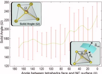
To verify our results we have calculated strain distribu-tion in NC region for all mendistribu-tioned measures. We have plot-ted all three of them in Fig. 1. The results of volumetric strain are very close to hydrostatic strain which is the trace of strain tensor calculated with aforementioned technique.23 In these results, we observe a net compressive behavior of strain just under the surface and a uniform tensile strain of about 1% at the core of NC. Si–Si bonds are stretched by about 1% in the core region in agreement with the hydro-static and volumetric strains, however, just under the surface, Si–Si bonds are stretched up to 3% where hydrostatic and volumetric strain results indicate compressive strain state. The bond stretch in Si–Si bonds due to oxidation has been shown earlier by us using MD simulations17which was also confirmed by other approaches.18Occurrence of compressive volumetric strain and stretched bond lengths in the same outer region may initially seem contradicting. However, stretching of bonds does not imply that the system is under tensile hydrostatic strain as well. Consider a tetrahedron formed by a Si atom and its four Si neighbors共A, B, C, D兲 as shown in upper inset of Fig. 2. In the ideal case, the solid angle 共⍀兲 subtended by each triangular face of this tetrahe-dron should be equal to 180°. Under a uniform deformation, bond lengths will also be stretched, while the solid angles remain unchanged. However, under a nonuniform deforma-tion, the change in three solid angles causes a decrease in the volume of the tetrahedron while increasing or preserving the bond lengths. Hence, a combination of stretched bond lengths with deformed solid angles may end up with an over-all reduction in the volume of the tetrahedron. This explains the coexistence of compressive volumetric strain and stretched bond lengths at the region just below the surface of NCs.
To better visualize the nature of the deformation of the Si NCs, we consider the orientational variation of the solid angles of the tetrahedral planes. As illustrated in the lower inset of Fig. 2, the two important directions are the unit normal 共nˆS兲 of the tetrahedron face subtending the solid angle under consideration, and the local outward surface nor-mal共nˆNC兲 of the NC. It is clearly seen from Fig.2that solid angles subtended by tetrahedra faces oriented outward to the
NC surface are increased up to 220°, whereas those facing inward to the NC core are decreased down to 160°. This dependence is a clear evidence of how oxidation affects strain distribution close to the interface.
To further quantify the atomistic strain in the highly critical region within 3 Å distance to the interface, we clas-sify the average bond length and hydrostatic strain behaviors into three categories. Figure3displays the percentage as well as the bonding details of each category. In top left, we illus-trate most common type with a share of 53.0% which is responsible for the opposite behavior in Fig.1where average bond lengths of center Si atoms to its four nearest neighbors are stretched but net atomistic strain at this atom is compres-sive. In this case solid angles facing toward the oxide region are increased to 270° due to oxygen bonds of Si neighbors.
Strain
(%)
Distance to the Surface (Å) 4 3 2 1 0 -1 -2 -3 -4 -12 -10 -8 -6 -4 -2 0 -5 0 -10 -5 0 5
FIG. 1. 共Color online兲 Variation of, Si–Si bond lengths 共squares兲, hydro-static strain共diamonds兲, and the volumetric strain 共triangles兲 as a function of distance to NC surface共see text兲. Dashed, dotted, and solid lines are guides to the eye for the respective data set. The data for 2.6 nm diameter NC are used. Inset: Other NC diameters ranging from 2.2 to 3.2 nm are also shown.
FIG. 2. 共Color online兲 Dependence of solid angle subtended by tetrahedron face to the angle between tetrahedron face and NC surface. Illustration of solid angle subtended by tetrahedron face 共top left inset兲 and the angle between tetrahedron face and NC surface共bottom right inset兲.
FIG. 3. 共Color online兲 Illustrations of oxidation effects on strain in three categories with their percentage of occurrences: Si–Si bonds are stretched and system is under compressive strain 共upper left兲. Si–Si bonds are stretched and system is under tensile strain共upper right兲. Si–Si bonds are shortened and the Si atom at the center is under compressive strain共bottom兲. Large spheres共gold兲 and small spheres 共red兲 represents Si and O atoms, respectively.
Although these oxygen bonds stretched Si–Si bonds to 2.41 Å, net strain on center Si atom is ⫺2.7%. In the top-right part of the Fig.3we illustrate second most often case with a percentage of 42.0%, where average bond lengths and atom-istic strain show similar behavior; bond lengths are stretched and net hydrostatic strain is tensile. In this case oxidation somewhat uniformly deforms the bonds so that solid angles are still around 180° which is the value for the unstrained case. Finally, as shown at bottom of Fig. 3, a very small percentage of atoms共5.0%兲 in the region beneath the surface have shortened bond lengths and compressive atomistic strain.
In summary, we study the strain state of Si NCs in silica matrix with diameters in 2–3.2 nm. The structure is assumed to be free from any thermal built-in strains. The core region of the NC is observed to be under a uniform 1% tensile strain, where both bond length and volumetric strain mea-sures are in agreement. However, toward the NC interface, while the Si–Si bonds become more stretched, the hydro-static strain changes in the compressive direction. In the in-terpretation of the indirect strain measurements, e.g., from spectroscopy, this dual character needs to be taken into con-sideration. We explain these two behaviors using the solid angle deformation of the tetrahedral-bonded Si atoms, and demonstrate that it is ultimately caused by the oxygen atoms at the interface. An equally important finding is that the over-all strain profile within the Si NCs is quite nonuniform. As very recently emphasized, within the context of centrosym-metric materials, such as silicon, such strain gradients locally break the inversion symmetry and may lead to profound physical consequences.25
This work has been supported by the Turkish Scientific and Technical Council TÜBİTAK with the Project No. 106T048 and by the European FP6 Project SEMINANO with the Contract No. NMP4 CT2004 505285. The visit of Tahir Çağın to Bilkent University was facilitated by the
TÜBİTAK BİDEB-2221 program. T.C. also acknowledges the support of NSF-IGERT.
1Nano Silicon, edited by V. Kumar共Elsevier, London, 2007兲.
2H. M. Manasevit, I. S. Gergis, and A. B. Jones,Appl. Phys. Lett.41, 464 共1982兲.
3R. People, J. C. Bean, D. V. Lang, A. M. Sergent, H. L. Stormer, K. W. Wecht, R. T. Lynch, and K. Baldwin,Appl. Phys. Lett. 45, 1231共1984兲. 4D. M. Lyons, K. M. Ryan, M. A. Morris, and J. D. Holmes,Nano Lett. 2,
811共2002兲.
5K.-H. Hong, J. Kim, S.-H. Lee, and J. K. Shin,Nano Lett. 8, 1335共2008兲. 6M. Zacharias and P. Streitenberger,Phys. Rev. B 62, 8391共2000兲. 7S. Hernandez, A. Martinez, P. Parinello, Y. Lebour, B. Garrido, E. Jordana,
and J. M. Fedeli,J. Appl. Phys. 104, 044304共2008兲.
8M. Zacharias, J. Bläsing, P. Veit, L. Tsybeskov, K. Hirschman, and P. M. Fauchet,Appl. Phys. Lett. 74, 2614共1999兲.
9A. Thean and J. P. Leburton,Appl. Phys. Lett. 79, 1030共2001兲. 10X. H. Peng, S. Ganti, A. Alizadeh, P. Sharma, S. K. Kumar, and S. K.
Nayak,Phys. Rev. B 74, 035339共2006兲.
11A. M. Smith, A. M. Mohs, and S. Nie,Nat. Nanotechnol. 4, 56共2009兲. 12G. Hadjisavvas and P. C. Kelires,Physica E 38, 99共2007兲.
13R. Guerra, I. Marri, R. Magri, L. Martin-Samos, O. Pulci, E. Degoli, and S. Ossicini,Phys. Rev. B 79, 155320共2009兲.
14R. Tsu, H. Shen, and M. Dutta,Appl. Phys. Lett. 60, 112共1992兲. 15T. Arguirov, T. Mchedlidze, M. Kittler, R. Rolver, B. Berghoff, M. Frost,
and B. Spangenberg,Appl. Phys. Lett. 89, 053111共2006兲.
16H. Coffin, C. Bonafos, S. Schamm, N. Cherkashin, G. B. Assayag, A. Claverie, M. Respaud, P. Dimitrakis, and P. Normand,J. Appl. Phys. 99, 044302共2006兲.
17D. E. Yılmaz, C. Bulutay, and T. Çağın,Phys. Rev. B 77, 155306共2008兲. 18M. Ippolito, S. Meloni, and L. Colombo,Appl. Phys. Lett. 93, 153109
共2008兲.
19A. C. T. van Duin, A. Strachan, S. Stewman, Q. Zhang, X. Xu, and W. A. Goddard III,J. Phys. Chem. A 107, 3803共2003兲.
20B. Joe,Adv. Eng. Software 13, 325共1991兲.
21P. M. Gullett, M. F. Horstemeyer, M. I. Baskes, and H. Fang, Modell.
Simul. Mater. Sci. Eng. 16, 015001共2008兲.
22W. A. Curtin and R. E. Miller,Modell. Simul. Mater. Sci. Eng. 11, R33 共2003兲.
23C. Pryor, J. Kim, L. W. Wang, A. J. Williamson, and A. Zunger,J. Appl.
Phys. 83, 2548共1998兲.
24P. C. Chou and N. J. Pagano, Elasticity-Tensor, Dyadic and Engineering Approaches共Dover, Princeton, 1967兲.
25M. S. Majdoub, P. Sharma, and T. Cagin,Phys. Rev. B 77, 125424共2008兲. 191914-3 Yılmaz, Bulutay, and Çağın Appl. Phys. Lett. 94, 191914共2009兲