Thermal stresses in a cylindrically curved FGM beam
Mehmet Haskul1*
1* Sirnak University; [email protected] * Corresponding Author; [email protected];
Tel. (+90 486 216 80 04)
Recieved Date: 02/05/ 2019 Accepted Date: 21/06/ 2019
ABSTRACT
In this study, the stress analysis of the cylindrically curved beam, which is functionally graded for thermal load in radial direction, has been analytically analyzed. The temperature distribution varies steadily state as a function of the radial coordinate. The beam is assumed to be in the plane strain state. The elasticity modulus of the functionally graded beam is assumed to vary with the power law in relation to the thickness of the beam. In addition, the effect of the vary in the power law parameter and with the general mixture law, all material properties of the beam (modulus of elasticity, density, thermal expansion coefficient, thermal conductivity coefficient and yield stress) except for Poisson's ratio change in radial direction. Thus, all material properties of the beam vary depending on the power law. Beam; stresses under positive, negative and homogeneous temperatures were examined. Stress analysis is considered according to Von Mises yield criterion.
Keywords: : Functionally graded materials (FGM); Curved beam; Thermal stress; Von Mises yield criteria
Silindirik Eğri Eksenli FDM Kirişte Isıl Gerilmeler ÖZET
Bu çalışmada, radyal doğrultuda sıcaklığa maruz fonksiyonel derecelendirilmiş malzemeden yapılmış silindirik olarak eğri eksenli kirişin gerilme analizi analitik olarak incelenmiştir. Sıcaklık dağılımı kararlı ve dengeli bir durum ve radyal koordinatın bir fonksiyonudur. Eğri eksenli kiriş düzlem şekil değiştirme durumunda olduğu varsayılmaktadır. Elastisite modülü üstel kuvvete göre kirişin kalınlığı doğrultusu boyunca değişmektedir. Buna ek olarak üstel kuvvet etkisi ve genel karışım kanunu birlikte uygulanarak kirişin diğer malzeme özellikleri (elastisite modülü, yoğunluk, ısıl genleşme katsayısı, ısıl iletim katsayısı ve akma dayanımı) Poisson oranı hariç radyal doğrultu boyunca değişmektedir. Bu durumda bütün malzeme özellikleri üstel kanuna göre değişmektedir. Pozitif, negatif ve homojen sıcaklıklar altında kirişte oluşan gerilmeler incelenmiştir. Gerilme analizi için von Mises akma kriteri uygulanmıştır.
Anahtar Kelimeler: Fonksiyonel derecelendirilmiş malzemeler (FDM), eğri eksenli kiriş, von Mises akma kriteri
1. INTRODUCTION
Curved beams are frequently used in engineering, and these structures are often
subjected to mechanical and thermal loads. Therefore, many researchers examined
deformation behaviors of these structures under different loads. Deformation behavior of curved beams and methods to increase the material limits of such bars under varying loads have received significant attention by researchers. Elastic analysis of wide curved bar has been given by Timoshenko and Goodier (1970). Shaffer and House (1957, 1954) have been obtained equations for the elastic-plastic stress distribution a perfectly plastic wide curved bar and displacements a perfectly plastic incompressible material wide curved bar subjected to pure bending. Arslan and Mack (2014) presented analytical solutions for the elastic-plastic behavior of the panel under the thermal load. Analytical solution of linear hardening elastic-plastic material in the work are investigated (Dadras, 2001; Eraslan and Arslan, 2008) and obtained the behavior for nonlinear hardening material by Arslan and Eraslan (2010). The
classical shell theory has studied the nonlinear behavior of curved panels under pressure and temperature (Librescu et al., 2000; Duc and Van Tung, 2010). Kiani et al. (2012) investigated the dynamic behavior of the functionally graded panel in the radial direction subjected to thermal and mechanical loads. Dryden (2007) studied elastic bending stresses of functionally graded curved bars. Mohammadi and Dryden (2008) investigated the the thermoelastic stress field in a functionally graded curved beam. Their work is obtained analtically where the radial variation of the stiffness is represented by a fairly general form. Eraslan and Akis (2006) have analytical solutions for plane stress and plane strain for the functionally graded rotating shaft and solid disk.
In this study, analytical solutions for the stress analysis in cylindrically curved FGM beam are derived under assumption of plane strain state. The analytical solution for the elastic limit and displacements of the curved FGM beam subjected to thermal and mechanical loads is obtained. It is assumed that the material properties of the beam (modulus of elasticity, density, coefficient of thermal expansion, coefficient of thermal conduction and yield stress) are varied in radial direction depending on the power law.
2. MATERIAL and METHOD
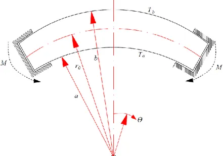
Stress analysis cylindrically FGM curved beam with a rectangular cross section (see Fig. 1) under plane strain condition is investigated. In addition, the beam is fixed in the cylindrical direction by rigid supports and these supports allow displacement on the end surfaces of the beam, but the radius of curvature of the central surface of the beam remains constant. Figure 1 shows the geometry of the curved beam with the inner radius a and the outer radius b.
Figure 1. Coordinate system used and curved beam
2.1 Statement of the Problem
The subject of the current investigation is a curved beam (see Fig. 1) with stress-free inner and outer cylindrical surfaces,
0,
r r a
(1)0.
r r b
(2)In the radial direction, the FGM curved beam is in plane strain state (εz = 0) and is radially
displaced by varying T=T (r) temperature distribution. Displacement of the beam in the radial direction;
0: 0
rr u (3) Since it is assumed that the initial middle surface where r0 = (a + b)/2 does not undergo a
radial displacement. Moreover, the couple moments M that occur at the rigid supports at the angular direction can be defined as
b
a
M
rdr (4) 2.2 Basic EquationsThe strain-displacement relations;
, r du dr (5) 1 , u v r r (6) 0. r v v r r (7) the equilibrium equation in the radial direction is;
( r) d r dr (8)
Taking into account a variable modulus of elasticity EE r( ) and a variable coefficient of thermal expansion ( )r , but Poisson's ratio (v) constant, the generalized Hooke's law can given as;
1 ( ) , ( ) r r z r T E r (9)
1 ( ) , ( ) r z r T E r (10)
1 0 ( ) . ( ) z z r r T E r (11)In order to describe the material properties at any point of the FGM curved beam, general linear mixture law is used. The general linear rule of mixture reads
0 0 1 1
Pr ( )eff r Pr V r( )PrV r( ) (12)
where Preff denotes material property, and subscripts 0 (zero) and 1 specifies the volume fraction of material. In addition, It has been suggested that there are pure components on the
inner surface of the curved beam, 0 (zero) of the FGM curved beam, i.e., 𝑉0(𝑎) = 1 and with
the index 1 indicating the second constituent, it is given as;
1( ) 1 0( ).
The modulus of elasticity is as follows: 0 ( ) , m r E r E a (14)
Eqs. (13) and (14) are substituted in Eq. (12) and a straight forward the relation of the volume fraction coefficient of the constituent 0 are obtained.
0 1 0 0 1 ( ) . m r E E a V r E E (15)
Then, applying the rule of mixture Eq. (12), the coefficient of thermal expansion α(r) and the density ρ(r),the uniaxial yield limit σy(r), and the thermal conductivity k(r), respectively, one
obtains r Pr Pr ( ) m eff P r r A B a (16) with
0 0 1 0 1 1 0 Pr Pr 0 1 0 1 Pr Pr Pr Pr , E E E A B E E E E (17)where Pr = α, ρ, σy, and k, respectively. It is assumed that the Poisson’s ratio v is assumed to
be constant. The properties of materials are connected to the radial coordinate.
Basic equations for FGM beam can be obtained. First, using Eqs. (11), (14), (16), (17) and
0
z
, the axial stress as follows
0 . m m z r r E T a r A B a (18)integration of relation (Eq. 7) gives
rf
(19)
where f is a function of θ only. Then, differentiating Eq. (6) with respect to θ and taking into account that both θ and u depend on r only, one obtains
2 2 0 (20) and hence; 1 C r (21)
with the (non-dimensional) constant of integration C1. Hence, based on Eqs. (5), (6), and
Hooke’s law (9), (10), σr, and σθ can be expressed in terms of u and its derivative with respect
1 0 1 , 1 1 2 1 m m r r u C E a r A T r B a u (22)
' 1 0 1 1 . 1 2 1 1 m m r E u a r A B T C r a u (23)where r and radial and circumferential stresses, respectively. Eqs. (22) and (23) are substituted in Eq. (8) to obtain the differential equation for displacement.
1 1 1 1 1 1 1 1 2 1 1 1 2 m m m m m m r m u r u m r u C m r T r r m A B a r A B a T (24) Its solution is
1 / 2 / 2 2 3 / 2 / 2 3 / 2 / 2 3 / 2 1 2 1 2 1 2 2 m S m S m S m r m S r m S S m a a r m S r m S m a a C r m u C r C r m S a r m S r a B Td A Td m S a B Td A Td
(25)where C2 and C3 are constants of integration, and
2 4 4 1 m S m (26)
Thereof, solving Eqs. (22) and (23), one finally obtains
2 / 2 1 0 0 3 2 / 2 3 / 2 2 / 2 0 2 / 2 3 / 2 1 2 1 1 2 2 2 2 2 1 2 m m S r m S r m S r m S S m m S a a m m r m S r m S a a r C E E r a m a C m S m S C r m S m S m S r a B Td A Td E r Sa m S a B Td A Td (27)
1 0 2 / 2 2 / 2 0 3 2 2 / 2 0 2 / 2 3 / 2 / 2 1 1 2 2 2 2 2 1 1 2 4 1 1 2 (m S 2) 2 (S m 2) 2 ( 2 (2 m S) m S m S m m S m r r m S m S S m a a m S m r C E m a m E C r m S C r m S a E r S a r a B Td A Td m S a B Td A
3 / 2 2 / 2 4 1 2 r r m S a a m S m m Td Sr a B r A T (28) and σz obtained from Eq. (18).In the above basic equations, the three constants of integration, C1, C2 and C3, must be
determined. For the determination of these unknowns, the conditions Eqs. (1)-(3) are available. These conditions lead to
1 1 3 2 0 1 1 2 1 2 2 (2 m S) m S S S S m C a L S L a b L a m S m S r m S (29)
2 1 0 1 3 2 / 2 2 / 2 0 3 2 0 1 2 1 2 2 2 2 2 1 2 1 2 2 1 2 2 2 2 m S S m S m S S S S S C a L S a m S m S r m S m S m S m S L L a r m m S m S L a b L r m S m S a m S m S (30)
2 / 2 3 1 0 / 2 1 3 2 / 2 / 2 / 2 0 3 2 0 1 2 1 2 2 2 2 2 1 2 1 2 2 1 2 2 2 2 m S S S S m S S S S S S a C SL a m S m S r m S m S a m S m S L L r a a m m S m S L a b L a m S m S r m S m S (31) where;
1 0 2 / 2 2 / 2 0 0 2 / 2 2 / 2 0 2 2 2 1 2 1 2 2 2 2 2 1 2 1 2 2 S S m S m S S S m S m S L b m S m S r m S m S a r m m S m S a m S m S r m S m S b r m m S m S (32) / 2 3 / 2 2 / 2 3 / 2 2 2 b m S b m S S m a a b m S b m S m a a L b m S a B r Tdr A r Tdr m S a B r Tdr A r Tdr (33) 0 0 0 0 / 2 3 / 2 3 0 / 2 3 / 2 2 2 r m S r m S S m a a r m S r m S m a a L r m S a B r Tdr A r Tdr m S a B r Tdr A r Tdr (34)In this way, after the temperature field is determined, the strain and stress in the beam can be known. Furthermore, by substituting the circumferential stress σθ given in Eqs. (28) and (4),
2 1 2 2 0 3 2 / 2 2 / 2 2 / 2 2 / 2 0 2 2 / 2 / 2 / 2 3 / 2 2 2 1 1 2 2 1 2 2 2 2 1 2 2 2 2 1 m m m m S m S m S m S m b m S r m S b m S r m S m a a a a C m S C m E M b a a m m m S C m S a b a b m S E m S m S Sa a B r Td dr A r Td
/ 2 / 2 / 2 3 / 2 1 1 2 0 2 2 2 . 1 b m S r m S b m S r m S m a a a a b m b m m a a dr m S m S a B r Td dr A r Td dr E B r Tdr A r Tdr a (35) 2.3 Temperature FieldWhen the temperature change is regarded as steady state, the temperature increase of inner or outer surfaces is thought to increase slowly and is calculated independently from time. In this case, it is governed by the differential equation (Peng and Li; 2010).
1 0 dT r d rk r r dr dr (36)With the dependence of the thermal conductivity on the radius given by Eqs. (16) and (17), its solution is
1 2 ln ln m k k k r D m r A B a T r D mB (37)where D1 and D2 are constants of integration. When the surface temperature at the inner and
outer sides is prescribed as;
a
bT a T T b T (38) and give rise to
ln / ln / ln / ln / ln ln / ln / ln / ln . ln / ln ln / m m k k k k a m k k k k m k k k k b m k k k k m r b A b a B A r a B T T r m b a A B A b a B m r a A r a B A B T m b a A B A b a B (39)3. STRESS DISTRIBUTIONS AND EFFECT OF EXPONENTIAL PARAMETER With the equations obtained above, the stresses can be calculated. The von Mises yield criterion was used to determine the elastic limits and as follows;
1 2 2 2 , . 2 M r y r M r z z r (40)
Now, introducing the following non-dimensional quantities: 2 0 0 ,0 , , , y k r E M k r E M k a E a (41)
0 0 ,0 0 ,0 0 , , i , i y y E T T (42)
where, it should be remembered that the pure FGM component of index 0, r = a, represents a
material parameter. The exponential grading index mext in the FGM beam is as follows;
1 ln . ln ext E m b (43)Thus, depending on whether E1>1 or E1<1, there hold the relations 0 m mext or
0
ext
m respectively.m
3.1 Positive, Homogeneous and Negative Temperature Gradient
Stress analysis for different temperature states of the aluminum/steel cylindrically curved FGM beam have been investigated analytically. Stress distributions are calculated according to different surface temperature conditions. To calculate numerically these equations, material properties and surface radius ratios are specified. In particular, a beam with radii ratio b/a=1.25, Poisson’s ratio ν=0.3, and E1/E0=2.86, α1/α0=0.72, k1/k0=0.21,
σy,1/σy,0=6.67, ρ1/ρ0=2.86 is obtained.
These surface temperature differences ( ) have been investigated in T Tb Ta
accordance with the exponential parameter m, ΔT>0, ΔT=0 and ΔT<0. Fig.2a presents the stresses, circumferential and radial displacements for m 1.60,𝑇̅𝑎 = 0 and ∆𝑇̅ = 1.683 the elastic limits in the curved FGM beam. The radial displacement is equal to zero where the center of curvature of the beam is the same as in equation 3. In addition, the radial stress is equal to zero as indicated in Eqs.1, 2 on the inner and outer surfaces of the beam. Circumferential and radial stresses vary from positive to negative. The volume ratio of the aluminum on the outer surface of the beam is calculated as 76.9% and the volume ratio of steel as 23.1%. The onset of the yield would occur at the inner surface of curved FGM beam. Fig.2b shows the stresses, circumferential and radial displacements for m 1.60,𝑇̅𝑎 = 1.026
and ∆𝑇̅ = 0 the elastic limits in the curved FGM beam. Angular stress and radial
displacement vary linearly from negative to positive value. The axial stress is negative. The onset of the yield would occur at the inner surface of curved FGM beam. Fig.2c determines the stresses, circumferential and radial displacements for m 1.60,𝑇̅𝑎 = 0.885 and ∆𝑇̅ = −0.885 the elastic limits in the curved FGM beam. The onset of the yield would occur at the inner surface of curved FGM beam. Fig.3a shows the stresses, circumferential and radial displacements for m 2.40,𝑇̅𝑎 = 0 and ∆𝑇̅ = 1.728 the elastic limits in the curved FGM beam. The volume ratio of the aluminum on the outer surface of the beam is calculated as 61.8% and the volume ratio of steel as 38.2%. The onset of the yield would occur at the inner surface of curved FGM beam. Fig.3b presents the stresses, circumferential and radial displacements for m 2.40,𝑇̅𝑎 = 1.026 and ∆𝑇̅ = 0 the elastic limits in the curved FGM beam. The onset of the yield would occur at the inner surface of curved FGM beam. Fig.3c presents the stresses, circumferential and radial displacements for m 2.40,𝑇̅𝑎 = 0.879 and ∆𝑇̅ = −0.879 the elastic limits in the curved FGM beam. The onset of the yield would occur at the inner surface of curved FGM beam. Fig.4a determines the stresses, circumferential and radial displacements for m 3.20,𝑇̅𝑎 = 0 and ∆𝑇̅ = 1.807 the elastic limits in the curved FGM beam. The volume ratio of the aluminum on the outer surface of the beam is calculated as 43.8% and the volume ratio of steel as 56.2%. The onset of the yield would occur at the inner surface of curved FGM beam. Fig.4b shows the stresses, circumferential and radial
displacements for m 3.20,𝑇̅𝑎 = 1.025 and ∆𝑇̅ = 0 the elastic limits in the curved FGM beam. The onset of the yield would occur at the inner surface of curved FGM beam. Fig.4c presents the stresses, circumferential and radial displacements for m 3.20,𝑇̅𝑎 = 0.875 and ∆𝑇̅ = −0.875 the elastic limits in the curved FGM beam. The onset of the yield would occur at the inner surface of curved FGM beam.
Figure 2. The distribution of stresses, circumferential, radial displacements and elastic limits for
1.60
m (a) Positive temperature (b) Homogenous temperature (c) Negative temperature
Figure 3. The distribution of stresses, circumferential, radial displacements and elastic limits
for m 2.40 (a) Positive temperature (b) Homogenous temperature (c) Negative temperature
Figure 4. The distribution of stresses, circumferential, radial displacements and elastic limits
for m 3.20 (a) Positive temperature (b) Homogenous temperature (c) Negative temperature
4. CONCLUSION
In this study, an analytical solution is investigated the stress analysis of the Aluminum/Steel curved FGM beam in the plane strain state under temperature in radial direction. It is considered that the temperature distribution changes as a function of the radial coordinate and is in steady state. The modulus of elasticity varies with the thickness of the
(c) (b) (a) (c) (b) (a) (c) (b) (a)
beam according to the power law. Accordingly, by applying the general mixture law, the thermal expansion, the heat transfer coefficient and the volume fraction vary depending on the exponential parameter (except Poisson ratio).
In particular, the effect of the exponential parameter values has been studied in detail, taking into account the radial direction of all properties of the materials (except for Poisson's ratio), depending on the general mixture law. It has been found that depending on the FGM beam exponential parameter, the elastic limit can be reached increasing temperature gradient at the inner surface, at the outer surface, or at both surfaces simultaneously.
Finally, although the closed-form solution given above requires certain assumptions for boundary conditions, it is quite remarkable that the remaining numerical effort is limited to the integration of the terms, which mainly include the analytically derived temperature field. Acknowledgments: This work is supported by Sirnak University Research Fund (BAP), Project no: 2017.03.05.01.
REFERENCES
Arslan, E., & Mack, W. (2014). Elastic-plastic states of a radially heated thick-walled cylindrically curved panel. Forschung im Ingenieurwesen, 78(1-2),1-11.
https://doi.org/10.1007/s10010-014-0170-1
Arslan, E., & Eraslan, A. N. (2010). Analytical solution to the bending of a nonlinearly hardening wide curved bar. Acta Mechanica, 210(1-2), 71-84.
https://doi.org/10.1007/s00707-009-0195-y
Dadras, P. (2001). Plane strain elastic–plastic bending of a strain-hardening curved beam. International journal of mechanical sciences, 43(1), 39-56.
https://doi.org/10.1016/S0020-7403(99)00102-2
Duc, N. D., & Van Tung, H. (2010). Nonlinear response of pressure-loaded functionally graded cylindrical panels with temperature effects. Composite Structures, 92(7), 1664-1672.
https://doi.org/10.1016/j.compstruct.2009.11.033
Dryden, J. (2007). Bending of inhomogeneous curved bars. International Journal of Solids
and Structures, 44(11-12), 4158-4166.
https://doi.org/10.1016/j.ijsolstr.2006.11.021
Eraslan, A. N., & Arslan, E. (2008). A concise analytical treatment of elastic‐plastic bending of a strain hardening curved beam. ZAMM‐Journal of Applied Mathematics and
Mechanics/Zeitschrift für Angewandte Mathematik und Mechanik: Applied Mathematics and Mechanics, 88(8), 600-616.
https://doi.org/10.1002/zamm.200600037
Eraslan, A. N., & Akis, T. (2006). On the plane strain and plane stress solutions of functionally graded rotating solid shaft and solid disk problems. Acta
Mechanica, 181(1-2), 43-63.
https://doi.org/10.1007/s00707-005-0276-5
Kiani, Y., Shakeri, M., & Eslami, M. R. (2012). Thermoelastic free vibration and dynamic behaviour of an FGM doubly curved panel via the analytical hybrid Laplace–Fourier transformation. Acta Mechanica, 223(6), 1199-1218.
https://doi.org/10.1007/s00707-012-0629-9
Librescu, L., Nemeth, M. P., Starnes Jr, J. H., & Lin, W. (2000). Nonlinear response of flat and curved panels subjected to thermomechanical loads. Journal of thermal
stresses, 23(6), 549-582. https://doi.org/10.1080/01495730050143134
Mohammadi, M., & Dryden, J. R. (2008). Thermal stress in a nonhomogeneous curved beam. Journal of Thermal Stresses, 31(7), 587-598.
https://doi.org/10.1080/01495730801978471
Peng, X. L., & Li, X. F. (2010). Thermal stress in rotating functionally graded hollow circular disks. Composite Structures, 92(8), 1896-1904.
https://doi.org/10.1016/j.compstruct.2010.01.008
Shaffer, B. W., & House Jr, R. N. (1957). Displacements in a wide curved bar subjected to pure elastic-plastic bending. J. Appl. Mech. Trans. ASME, 24, 447-452.
Shaffer, B. W., & House, R. N. (1954). The elastic-plastic stress distribution within a wide
curved bar subjected to pure bending. NEW YORK UNIV BRONX SCHOOL OF
ENGINEERING AND SCIENCE.
Timoshenko, S.P. and Goodier, J.N. (1970) Theory of Elasticity, 3rd ed. McGraw-Hill, New York.