International Symposium “Steel Structures:Culture & Sustainability 2010” 21-23 September 2010, Istanbul, Turkey
STRENGTH OF SLOTTED STAINLESS STEEL TUBULAR MEMBER
TENSION CONNECTIONS
Güven KIYMAZ1, Edip SEÇKİN2
1
Assistant Professor, İstanbul Kültür University, Faculty of Engineering and Architecture, Department of Civil Engineering
2
Research Assistant, İstanbul Kültür University, Faculty of Engineering and Architecture, Department of Civil Engineering
ABSTRACT
In the present study, shear lag induced failure of slotted end tension connections is considered for circular hollow section members in stainless steel. The failure of slotted end tension connections is mostly governed by fracture near the slotted end where local peak stress concentrations develop due to shear lag. Within the connected region, shear lag causes the unconnected circumferential region of the hollow section to lag behind the welded region in resisting the axial tensile forces. An experimental program carried out on 10 slotted gusset plate welded stainless steel circular member end connections is first described. The results obtained from the test program are critically examined and compared with currently available design guidance for slotted gusset plate welded tubular end connections. It is noted that no specific rules exist in international specifications on structural stainless steel which cover the design of such connections. Therefore, the results of this study are compared with the design rules for carbon steel. It is suggested that present requirements for such connections in carbon steel may be different if applied to stainless steels. Keywords: stainless steel, slotted circular hollow section, square hollow section
INTRODUCTION
Steel construction has an important role to play within the sustainable development agenda of nations which recognize the need to move towards more sustainable constructions. Various merits of steel construction such as speed, safety, minimal impact on community and minimal production of waste when under construction, improved in-use life performance and end-of-life recoverability and recyclability are the main reasons which put steel at forefront of sustainable construction materials.
Among the various types of steel, stainless steel is maybe the most sustainable type mainly due to its favorable properties such as improved corrosion and fire resistance. The use of stainless steel for civil engineering structural applications provides possibilities for a more efficient balance between whole-life costs and in-service performance (Di Sarno et al. 2003). Combined with these advantages, its favorable strength and ductility properties would make stainless steel a material of choice in structural applications. However, relatively high initial cost of stainless steel is one burden
for its structural use. To achieve a safe and economic design it is necessary to investigate the mechanical response of structural components, connections and the overall system, thus leading to efficient design (Di Sarno et al. 2003). With this respect, research studies on structural stainless steel (Aoki H., 2000, Burgan et al., 2000, Johansson et al. 2000, Khoki et al., 2000) has mostly covered issues that focus on more suitable design of structural stainless steel members and their connections.
Cold-formed stainless steel tubular sections, in particular, are becoming popular as a construction member and hence attract research efforts to determine their structural properties and the behaviour of their connections. In structural applications one practical and inexpensive way of making the end connections of tubular members is applying the “slotted end connection”. In this type of connection the end connection is made by slotting the tube longitudinally, inserting the gusset plate and then placing longitudinal fillet welds at the tube-to-plate interface. A schematic view for such connections is given in Figure 1. The research presented in this paper has studied the behaviour and design of slotted end connections of stainless steel circular hollow section (CHS) members under static axial tensile loading. The failure of slotted end tension connections is mostly governed by fracture near the slotted end where local peak stress concentrations develop due to shear lag. Within the connected region, shear lag causes the unconnected circumferential region of the hollow section to lag behind the welded region in resisting the axial tensile forces (Korol, 1996). Previous experimental investigation has shown that shear lag induced failure in slotted end hollow section connections manifests itself either as a block shear type of failure where the crack developing at the stress concentration region propagates into the hollow section along the weld or as a circumferential tensile fracture where the crack propagates around the tube circumference (Martinez et al., 2006). This underlying mechanism for shear-lag induced failure of slotted end hollow section tension connections is also explained in other related research studies (Cheng et al., 1998, Willibald et al., 2006, Ling et al., 2007, Martinez et al., 2008, Martinez et al., 2009). In these studies design recommendations mostly based on experiments are also proposed which generally form the basis for the design provisions given in the codes of practice. In the present study, shear lag induced failure of slotted end tension connections is considered for circular hollow sections (CHS) in stainless steel. An experimental program carried out on 10 slotted gusset plate welded stainless steel CHS end connections (see typical test specimen in Figure 2) is first described. The results obtained from the test program are critically examined and compared with currently available design guidance for slotted gusset plate welded CHS end connections. It should be noted that no specific rules exist in international specifications on structural stainless steel which cover the design of such connections. Therefore, the results of this study are compared with the design rules for carbon steel. It is suggested that present requirements for such connections in carbon steel may be different if applied to stainless steels.
Figure 2. View of the test specimen
DESIGN RECOMMENDATIONS FOR SLOTTED GUSSET PLATE WELDED END TENSION CONNECTIONS
The resistance of a steel tension member is given as the minimum of the resistance in yielding of the gross section area (Pn =Fy.Ag) and the resistance in fracture of an effective net section area (Ae) within the connection region (Pn =Fu.Ae). The effective area is used to determine the efficiency of the connection under the effects of shear lag and calculated by using a shear lag reduction coefficient,U. Design rules related to failure of slotted end tension connections with welded gusset plates can be found in three major international specifications on steel structures namely the American AISC 360 (2005), the Canadian CAN/CSA-S16 (2001) and the European EN1993-1-8 (2005). Design methods adopted in these specifications are shown in Table 1 and Table 2 for shear lag and block shear tensile fracture failures respectively. Note that in EC3 Part 1.8 there are no design provisions for shear lag effect for such connections in hollow sections. In this design guide, rules for shear lag effect is given only for bolted connections for angles connected by one leg and other unsymmetrically connected tension members. Comparing the approaches adopted in these codes it is noted that for block shear failure the three codes present similar resistance equations. Nominal resistances predicted by these codes are equal (a slightly different value predicted by EC3 in which shear yield coefficient is taken as the theoretical 1 3value) but the design resistance values differ due to different resistance factors adopted in each code. However, it should be noted that in the block shear design equation of CSA (2001), the multiplication of two factors (0.85 and 0.90) equals 0.765 which is very close to the resistance factor used in the design equation of AISC (2005) which is 0.75. On the other hand, the resistance factor adopted in EN1993-1-8 (2005) is
25 . 1
1 which is again equal to a close value of 0.80. As for shear lag effect two general approaches are adopted. As presented in Table 1, shear lag coefficient, U, is calculated as a function of the ratio of the eccentricity of the connection (x) to the weld length (Lw) in the American specification whereas in the Canadian specification U is a function of the ratio of the weld length (Lw) to circumferential distance between the welds (w). In both specifications the adverse effect of shear lag decreases as weld length Lw increases. In the American specification shear lag factor U is taken as unity for Lw ≥1.3D and in the Canadian specification this limiting value is given as
w
Lw ≥2.0 or assuming w=π.(D 2) this value becomes Lw ≥1.57D. Therefore a more conservative limit is adopted in the Canadian specification. For weld lengths smaller than the smallest specified limits for shear lag i.e. Lw <1.0D in AISC (2005) and Lw <1.0w in CSA (2001) specifications , the collapse behaviour tends to be governed by a block shear type of failure. In between these upper and lower limits design equations are given for the calculation of shear lag coefficient,U.
The design of structural stainless steel members and connections are covered in Eurocode 3 - Design of steel structures - Part 1-4: General rules - Supplementary rules for stainless steels (EN 1993-1-4: 2006) and the American ASCE Specification for the Design of Cold-Formed Stainless Steel Structural Members, SEI / ASCE (2002). In both specifications, no specific rules exist which cover the design of slotted end tension connections with welded gusset plate.
Table 1 Design provisions for shear lag in circular hollow sections (CHS) with slotted end connection with single welded concentric gusset plate
Specification Shear lag coefficient, U Validity range AISC (2005) Lw x U = 1− for 1.3D>Lw≥D 1 = U for Lw ≥1.3D (CHSonly) D Lw≥ CSA (2001) 1 = U for Lw w≥2.0 w L U =0.5+0.25 w for 2.0>Lw w≥1.0 w L U =0.75 w for Lw w<1.0 N.A
Table 2 Design provisions for block shear (tear-out)
AISC (2005) Tr +Vr =φUbsAntFu +0.6φAgvFy ≤φUbsAntFu +0.6φAnvFuin which 75 . 0 = φ and Ubs =1.0 CSA (2001) Tr +Vr =φAntFu +0.6φAgvFy≤φAntFu +0.6φAnvFuin which φ=0.9 Eurocode (2005) nv y M u nt M r r V A F A F T 3 1 1 1 0 2 γ γ + = + γM0 =1.0,γM2 =1.25
DESCRIPTION OF THE EXPERIMENTAL PROGRAM
As stated earlier tests were carried out on 10 stainless steel CHS members with slotted gusset plate welded end connections. Two parameters that were considered as variables in the test program were the fillet weld length Lwand the end condition of the welded gusset plate inside the slot being welded or non-welded. These end conditions are shown in Figure 3. The welded end is denoted as RW (return weld) and the non-welded end is denoted as NW (no return weld).
Figure 3 View of the slot end conditions
As shown in the photographs given in Figures 2 and 3 rigid gusset plates with 15mm plate thickness were welded into the slots at both ends of the specimen. Tensile load was applied via these plates which were gripped inside the grip locations within the universal test machine with a total capacity of 50 tons. Loading was applied in the direction of the longitudinal axis of the member as concentric axial tensile load and specimen longitudinal elongation was monitored and recorded by using two displacement transducers attached to the sides of the specimen. Specimen dimensions are
RW: Return weld
NW:
reported in Table 1. In the specimen reference, C stands for Circular and L defines the length of weld. x/Lw, Lw/w and Lw/D ratios are all called weld length ratios used in the design
calculations as described above. Five different weld lengths were considered starting from 30mm up to 105 mm. Of the 10 specimens, 5 were without a return weld (NW) and the other 5 with a return weld (RW) at the slotted end. A constant diameter of D=76.1mm and thickness of t=2.0mmwas used for all the 10 specimens tested.
Table 1 Dimensional properties of the test specimens
Specimen reference w(mm) x(mm) Lw(mm) x/Lw Lw/w Lw/D C-L30-RW 104.54 24.22 30 0.81 0.29 0.39 C-L45-RW 104.54 24.22 45 0.54 0.43 0.59 C-L60-RW 104.54 24.22 60 0.40 0.57 0.79 C-L76-RW 104.54 24.22 76 0.32 0.73 1.00 C-L105-RW 104.54 24.22 105 0.23 1.00 1.38 C-L30-NW 104.54 24.22 30 0.81 0.29 0.39 C-L45-NW 104.54 24.22 45 0.54 0.43 0.59 C-L60-NW 104.54 24.22 60 0.40 0.57 0.79 C-L76-NW 104.54 24.22 76 0.32 0.73 1.00 C-L105-NW 104.54 24.22 105 0.23 1.00 1.38
Material Property Tests
Tensile tests were carried out on three tensile test coupons cut out from randomly selected CHS members to determine the material property of the stainless steel used. A rounded material behavior is observed with no well-defined yield point (Figure 4). An average yield stress of 500MPa (0.2% proof stress) and an average ultimate tensile stress level of 700MPa was achieved which were used for the strength estimations for the tested members using the above explained design rules.
0 100 200 300 400 500 600 700 800 0 10 20 30 40 50 60 Strain (%) S tr e s s ( M P a ) C1 C2 C3
TEST RESULTS and DISCUSSION
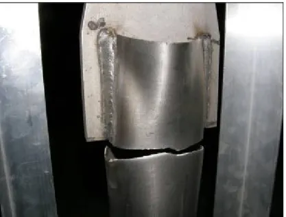
Experiments were carried out as described above for the 10 different specimens with varying design strength values. The three possible failure modes that would be expected for the members with slotted end connections are yielding of the member gross cross section, block tear out of material close to the weld region and shear lag failure with fracture of the effective net cross section around the circumference of the member. Of these failure types, all the specimens in the test program failed by circumferential fracture (CF) due to shear lag as defined earlier. Figure 5 shows a typical connection failure. A nearly perfect circumferential fracture of the whole circular hollow cross section occurred with crack propagating around the member circumference.
Figure 5 Typical failure mode observed in all the test specimens
Figure 6 shows close-up views of the failed specimens around the slotted end region both for “Return Weld (RW)” and “No Return Weld (NW)” cases. In both cases fracture initiated at the slotted end region due to high stress concentrations. For the NW cases, crack initiation was relatively easier in comparison to the RW (return weld) cases where the tensile load was at some point high enough to initiate a crack with the return weld material (photo on the left).
Figures 7 and 8 present load displacement response curves for the NW and RW cases, respectively. In general the behavior of the RW and the NW specimens are similar with close initial stiffness values and a rounded overall load-displacement response. However, for the RW cases for all the 5 specimens a sudden drop in strength is observed right after the maximum load is achieved whereas for the NW specimens a smooth transition is noted. The maximum load levels after which a sudden drop is observed for the RW members correspond to load levels at which crack initiation was observed to occur during the tests within the return weld material. In other words, as soon as the return weld cracked a sudden drop in load occurred. On the other hand for the “No return weld” specimens, load was not as sensitive to the crack initiation which started directly on the CHS member material near the slotted end – gusset plate juncture where there is no return weld. With this respect, a more ductile behavior is observed for the specimens with their slotted ends un-welded to the gusset plate. In general the RW specimens reached higher ultimate loads than the NW specimens but apparently at higher elongation levels.
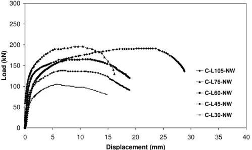
0 50 100 150 200 250 300 0 5 10 15 20 25 30 35 40 Displacement (mm) L o a d ( k N ) C-L105-NW C-L76-NW C-L60-NW C-L45-NW C-L30-NW
Figure 7 Load-displacement curves for the ‘No return weld (NW)’ specimens
0 50 100 150 200 250 300 0 5 10 15 20 25 30 35 40 Displacement (mm) L o a d ( k N ) C-L105-RW C-L76-RW C-L60-RW C-L45-RW C-L30-RW
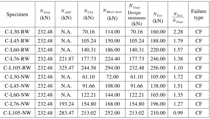
In an attempt to find out how well the current design rules for such connections in carbon steel apply to stainless steel cases Table 2 was prepared. Table 2 presents code estimations for the test specimens and compares the minimum of the estimated values (NFinal ) calculated for various failure modes and using different codes with the test maximum strength values,NTest. Note that the code values are all nominal values i.e. partial safety factors were set to unity. Also note that these values were calculated using the material property values given earlier in the paper.
Among the design estimations, the Canadian CSA shear lag fracture strength estimations (NCSA) are the most conservative. It also covers a wider range of weld lengths whereas the AISC does not cover smaller weld lengths as also explained above in Table 1. Therefore note that the design minimum values used for comparison with test are mostly equal to the Canadian CSA values. One important finding here is that these values are all for circumferential shear lag fracture and hence also well represents the failure type observed for the specimens as circumferential fracture.
Table 2 Comparsion of test failure strengths with code estimated nominal resistance values
Specimen NYield (kN) AISC N (kN) CSA N (kN) shear Block N (kN) Final N Design minimum (kN) Test N (kN) Final Test N N Failure type C-L30-RW 232.48 N.A. 70.16 114.00 70.16 160.00 2.28 CF C-L45-RW 232.48 N.A. 105.24 150.00 105.24 188.00 1.79 CF C-L60-RW 232.48 N.A. 140.31 186.00 140.31 220.00 1.57 CF C-L76-RW 232.48 221.87 177.73 224.40 177.73 246.00 1.38 CF C-L105-RW 232.48 325.47 244.58 294.00 232.48 256.00 1.10 CF C-L30-NW 232.48 N.A. 61.10 72.00 61.10 105.00 1.72 CF C-L45-NW 232.48 N.A. 91.66 108.00 91.66 138.00 1.51 CF C-L60-NW 232.48 N.A. 122.21 144.00 122.21 165.00 1.35 CF C-L76-NW 232.48 193.24 154.80 168.00 154.80 196.00 1.27 CF C-L105-NW 232.48 283.47 213.02 252.00 213.02 210.00 0.99 CF CF: Circumferential Fracture
Comparing the test maximum strengths (NTest) with the above defined design minimum values (NFinal) it is observed that for higher weld lengths both for RW and NW cases there is a relatively good agreement whereas for smaller weld lengths the test results become higher than the design values.
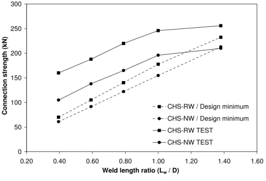
Figure 9, presents a comparison of experimental ultimate loads (NTest) with minimum code strength predictions (NFinal) both for RW and NW cases on a “connection strength”-versus-“weld length ratio Lw/D” plot. It is easier on this plot to see that the test maximum strengths are in general
higher than the design estimations. Note also that for RW cases a much higher difference is observed. On the other hand it is noted that for the highest weld length a closer agreement is achieved both for RW and NW specimens.
0 50 100 150 200 250 300 0.20 0.40 0.60 0.80 1.00 1.20 1.40 1.60
Weld length ratio (Lw / D)
C o n n e c ti o n s tr e n g th ( k N ) CHS-RW / Design minimum CHS-NW / Design minimum CHS-RW TEST CHS-NW TEST
Figure 9 Comparison of experimental ultimate loads with minimum code strength predictions
CONCLUSIONS
In this paper, shear lag induced failure of slotted end tension connections is investigated for circular hollow section members in stainless steel. An experimental program was carried out on 10 slotted gusset plate welded stainless steel circular member end connections. Two parameters that were considered as variables in the test program were the fillet weld length Lwand the end condition of the welded gusset plate inside the slot being welded or non-welded. All the specimens in the test program failed by circumferential fracture (CF) due to shear lag with fracture initiating at the slotted end region due to high stress concentrations both for slot end welded (RW) and un-welded (NW) cases. Load-displacement response curves for the specimens were plotted and comparisons were made mainly between the RW and NW cases. For all RW specimens a sudden drop in strength is observed right after the maximum load is achieved whereas for the NW specimens a smooth transition is noted. With this respect, a more ductile behavior is observed for the specimens with their slotted ends un-welded to the gusset plate. In general the RW specimens reached higher ultimate loads than the NW specimens but at higher elongation levels. The maximum strength results obtained from the test program were compared with currently available design guidance for slotted gusset plate welded tubular end connections. It is noted that no specific rules exist in international specifications on structural stainless steel which cover the design of such connections. Therefore, the results of this study were compared with the design rules for carbon steel. It was observed that for higher weld lengths both for RW and NW cases there is a relatively good agreement between design and test maximum strengths whereas for smaller weld lengths the test results become higher than the design values. In general, the test maximum strengths are higher than the design estimations. Therefore, this research has provided evidence for the need for possible adjustments in the current design formulations for carbon steel if they will be applied to the design of slotted gusset plate welded CHS connections in stainless steel.
Acknowledgement
The authors greatfully acknowledge the funding provided by Istanbul Kultur University for the test program. Also they wish to thank Mr. Korhan Deniz Dalgıç, research engineer at the Department of Civil Engineering, for his help with the experiments.
REFERENCES
Di Sarno L., Elnashai A.S. and Nethercot D.A. (2003) Seismic performance assessment of stainless steel frames. Journal of Constructional Steel Research, 59 1289–1319
Aoki H. (2000) Establishment of design standards and current practice for stainless steel structural design in Japan. Journal of Constructional Steel Research 54(1):191–210.
Burgan BA, Baddoo NR, Gilsenan KA. (2000) Structural design of stainless steel members: comparison between Eurocode 3, Part 1.4 and tests results. Journal of Constructional Steel Research 54(1):51–73.
Johansson B, Olsson A. (2000) Current design practice and research on stainless steel structures in Sweden. Journal of Constructional Steel Research 54(1):3–29.
Kouhi J., Talja A., Salmi P., Ala-Outinen T. (2000) Current R&D work on the use of stainless steel in construction in Finland. Journal of Constructional Steel Research 54(1):31–50.
Martinez-Saucedo G., Packer J.A., Willibald S. (2006) Parametric finite element study of slotted end connections to circular hollow sections. Engineering Structures, 28, Pages 1956-1971
Korol RM. (1996) Shear lag in slotted HSS tension members. Canadian Journal of Civil Engineering 23:1350-4
Willibald S. and Martinez-Saucedo G. (2006). Behaviour of gusset plate connections to ends of round and elliptical hollow structural section members. Canadian Journal of Civil Engineering 33 (4), 373-383
Cheng Roger, J.J., Kulak, G.L and Khoo, H.A. (1998). Strength of slotted tubular tension members. Canadian Journal of Civil Engineering 25:982-991
Ling, T.W., Zhao, X.L., Al-Mahaidi, R. and Packer, J.A. (2007) Investigation of shear lag failure in gusset plate welded structural steel hollow section connections. Journal of Constructional Steel Research 63, 293–304
Martinez-Saucedo G., Packer J.A and Christopoulos, C. (2008) Gusset plate connections to circular hollow section braces under inelastic cyclic loading. Journal of Structural Engineering, ASCE, 134:7, 1252-1258.
Martinez-Saucedo G. and Packer J.A. (2009). Static design recommendations for slotted end HSS connections in tension. Journal of Structural Engineering, ASCE, 135:7, 797-805.
ANSI/AISC 360 (2005) Specification for structural steel buildings, Chicago: American Institute of Steel Construction (AISC)
CAN/CSA-S16 (2001). Limit states design of steel structures, Toronto Canadian Standards Association (CSA).
EN1993-1-8 (2005) Eurocode 3 Design of steel structures- general rules—part 1–8: Design of Joints, Brussels: European Committee for Standardisation.
EN1993-1-4 (2006) Eurocode 3 Design of steel structures - Part 1-4: General rules – Supplementary rules for stainless steels, Brussels: European Committee for Standardisation.
SEI / ASCE (2002) 8-02. Specification for the design of cold-formed stainless steel structural members. American Society of Civil Engineers