FDTD Simulations of Multiple GPR Systems
Ugur Oguz and Levent Giirel
Department of Electrical and Electronics Engineering Bilkent University
Bilkent, Ankara, Turkey ([email protected], [email protected])
1. Introduction
A typical ground-penetrating-radar (GPR) configuration consists of transmitting and receiving antennas, and a shielding/absorbing structure to isolate the two antennas [I]. Such systems have been successfully employed in the detection of buried targets, such as anti-personnel land mines. However, the amount of time needed to perform a successful detection may be large, since a full-scale two- dimensional (2-D) search of the area is required.
One solution to this problem is to employ multiple GPR units in a single detection system. In this paper, simulations of a detection system employing two
GPR
units will be given. It will be shown how this new system enhances the detection process by illuminating and covering a broader footprint on the ground. Moreover, it will also be shown that, a system with multiple GPK units can provide information on the position of the target in the transverse axis that is perpendicular to the direction of the GPR movement, in addition to the longitudinal position in the axis of movement.The finite-difference time-domain (FDTD) method is perhaps the most compatible numerical technique in the analysis of GPR systems and subsurface-scattering mechanisms. The reason for this convenience is the easy modeling of a multilayer problem space and large number of inhomogeneities embedded in it. The adaptability of the perfectly-matched layer (PML) absorbing boundary conditions (ABCs) to lossy and layered media improves the suitability of the FDTD to simulate GPR scenarios [2].
2. Multiple-GPR System
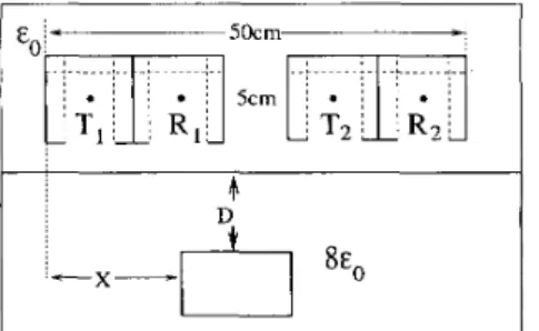
A multiple-GPR scenario, displayed in Fig. 1, consists of air, ground, the buried target, and the radar unit. In this work, the air is modeled by vacuum, ground is modelled by a homogeneous lossy dielectric half-space, with 8 ~ , permittivity, and the buried target is modeled by a conducting prism. The system employs two GPR units, each containing a transmitter and a receiver that are isolated by conducting shields and simulated absorbers [I]. The two GPR units are located side by side, with a 5-cm gap between them. The GPR system is 50 cm wide in total and located 7.5 cm above the ground. The transmitting antennas are x-polarized dipoles, modeled by Yee cubes of constant current density. The receivers are also modeled as small dipoles that sample the x component of the electric field in time. The time variation of the current source on the transmitter is given in [I].
The new GPR system works as follows: At a given time, only one of the two transmitters operate and the two receivers record the signals they observe. By altematively operating two transmitters and recording two signals for each operation, the GPR system provides four signals at each discrete GPR location. By comparing the relative amplitudes of these four signals, it may be possible to detect the transverse position,
X
in Fig. 1, of the buried target. The longitudinal position of the target in the direction of the GPR movement can be extracted &om the largest scattered signals observed in a B-scan measurement. Therefore, using a multiple- GPR system, it may be possible to extract the target location knowledge by performing a B-scan measurement. Using a single-GPR system, however, such a knowledge can only be obtained by performing a C-scan measurement.Figure 1: The typical GPR problem and the configuration with two units.
3. Simulation Results
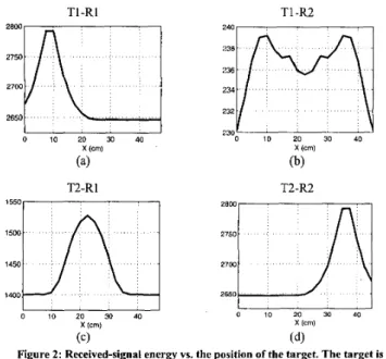
In this section, the results of simulations performed at a stationary point above the ground, i.e., A-scan results, will be presented. Different scenarios are considered with a perfectly conducting square prism of 5 cm width and 4 cm height that is buried at various depths under the ground with 8 ~ , permittivity. In each scenario, the horizontal position of the target is varied from
X
= 0 toX
= 45 cm . For each target position, with the two transmitters operating at 500 MHz center frequency and the two receivers recording simultaneously, four recorded signals are obtained. These signals are named as TI-R1, TI-R2, T2-R1, and T2-R2, which denote the combination of transmitting and receiving antennas. The energies of each of these signals are computed and presented in a single plot to reveal the effect of the transverse target position as observed by the four transmitter-receiver pairs. For the case of target buried 8 cm under the ground, Figs. 2(a)-(d) present four energy plots for T1-RI, TI-R2, T2-R1, and T2-R2, respectively. It is important to note that the manifestations of the effect of the transverse target position are remarkably different in these four plots. For instance, TI -R1 displays a peak for the target location X = 10, whereas T2-R2 has a low flat value. Similarly, TI-= and T2-RI also display completely different behaviours for the same scenario. This variation offers an opportunity to determine the transverse location of the target by using a suitable detection algorithm.In Figs. 2(a)-(d), the energy levels never drop to zero since the recorded signals are the total received signals. The total received signal includes both direct coupling from the transmitter and the ground reflection in addition to the target signal. Therefore, the flat portion of the energy plot in Fig. 2(a) contains very low scattered signal energy.
Comparison of Fig. 2(a) to 2(d) reveals that the signals obtained by pairs TI-RI and T2-FG! are identical, due to the symmetry. Figure 2(c) demonstrates that the maximum energy received by T2-R1 is slightly less than the energy received by TI-R1 and T2-R2 since the transmitter-receiver distance is 5 cm larger for this case, due to the gap between the two GPR units. Comparison of Fig. 2(b) to the other three figures reveals that, due to the large distance between the transmitter-receiver pair, TI-FG! signal is significantly smaller than TI-RI, T2-R2, and T2-R1 signals.
TI-R1 T1-R2
(a)
T2-R1 (b) T2-R2 (c) (dlFigure 2: Received-signal energy vs. the position of the target. The target is a conducting prism buried 8 cm under the ground.
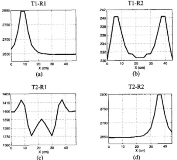
Another set of simulations, with target depth altered to 4 cm, is performed and the results are given in Fig. 3. Comparison with Fig. 2 demonstrates that the overall variation of the energy with respect to the target position does not change for T1-RI and T2-R2. The maximum energy received by T1-RI pair and the rate of change of energy with respect to X are almost the same for 8 cm and 4 cm deep targets, as demonstrated by Figs. 2(a) and 3(a). However, the TI-R2 and T2-RI pairs, which record lower energy levels, are affected by the depth of the target.
4. Concluding Remarks
In this work, a multiple-GPR detechon system has been simulated. The main advantage of such a system is that it saves hme by detecting both the transverse and the longitudinal positions of the target by a B-scan measurement, whereas the same detection can be achieved by a C-scan with a single-GPR system. FDTD method is employed to perform the simulations, in which the ground is homogeneous and the target is perfectly conducting.
Acknowledgments
This work was supported by the Turkish Academy of Sciences in the framework of the Young Scientist Award Program
(LG/TUBA-GEBIP/2002-1-12)
and by Bilkent University under research fund EE-01-01.T1-R1 T1-R2 2800
2750r1
2700;m
2650 0 10 20 30 40 2300 2o 30 40 T2-R1 T2-R2 1420:m
1390 1380 1370 1360 0 10 20 30 40 x (cm) 0 10 20 30 40 X (cm) (c) ( 4Figure 3: Received-signal energy vs. the position of the target. The target is a
conducting prism buried 4 cm under the ground. References
[ l ] U O@z and L. Gurel “Modeling of ground-penetrating-radar antennas with shields and simulated absorbers,” IEEE Trans. Antennas Propagat, vol 49, no 1 I , pp. 1560-1567,Nov. 2001.
[2] L Gurel and U OgUz, “Simulations of ground-penetrating radars over lossy and heterogeneous grounds,” IEEE Trans Geoscr Remofe Sensing, vol 39, no. 6 , pp 1190-1 197, June 2001