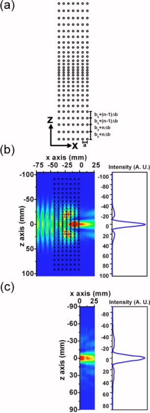
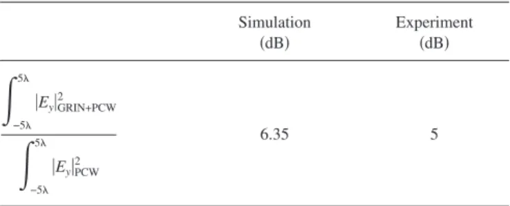
High efficiency of graded index photonic crystal as an input coupler
Tam metin
Şekil

Benzer Belgeler
Bu bağlamda, bu araştırma, öğrencilerin, armoni eğitiminde zorluk çektikleri konular, zorluk çekmelerinin sebepleri ile bu sorunları aşabilmelerinde etkili olabilecek
Bu eksikliğin giderilmesi bakımından bu araştırmada kültürel coğrafya bakış açısı Bergama halılarına, kültür bölgesi, kültürel yayılma, kültürel etkileşim,
The content and the chemical composition of volatile oil isolated from Pinaceae family depends on the geographic origin [9], the part of the plant material (needles, twigs,
If we know (i) the execution plan of each query, (ii) an estimated cost for each operator/plan, and (iii) the target multicore platform in advance, we can suggest compile-
A view of Shared Variable from 20,000 feet Shared Variable Client Transport Shared Variable Server. Stub Side Data Type Stub Side Transport Server Side Transport Server
This kind of conducting polymer synthesis not only improves the poor mechanical and physical properties of heterocyclic polymers but also retains the con- ductivity to a
In [7] the following conjecture was formulated: any onedimensional model with discrete (at most countable) spin space and with a unique ground state has a unique Gibbs state
Regenia Gagnier’s Individualism, Decadence, and Globalization: on the Relationship of Part to Whole, 1859–1920 (2010) and Tanya Agathocleous’s Urban Realism and the
