Progressive Refinement
Radiosity
on Ring-Connected
Multicomputers
*
Tolga
K.
Capin,
Cevdet
Aykanat,
Biilent
Ozgiic
D e p a r t m e n t
of
C o m p u t e r Engineeringand
Information Science Bilkent University06533
Bilkent,Ankara,
T u r k e yAbstract
T h e progressive refinement method is investigated for paral- lelization on ring-connected multicomputers. A synchronous scheme, based on static task assignment, is proposed, in order to achieve better coherence during the parallel light distribution computations. An efficient global circulation scheme is proposed for the parallel light distribution compu- tations, which reduces the total volume of concurrent com- munication by an asymptotical factor. T h e proposed par- allel algorithm is implemented on a ring-embedded Intel's iPSC/2 hypercube multicomputer. Load balance quality of the proposed static assignment schemes are evaluated ex- perimentally. T h e effect of coherence in the parallel light distribution computations on the shooting patch selection sequence is also investigated.
Keywords : Progressive refinement radiosity, parallel com- puting, multicomputers, ring interconnection topology.
1
Introduction
Radiosity [7] is an increasingly popular method for gener- ating realistic images of nonexisting environments. T h e re- cently proposed progressive refinement vadiosity [4] allows to view the approximated partial radiosity solutions initially and approaches to the correct solution iteratively. However, the operations still require excessive computational power and limit the usage of the method for complex scenes with a large number of patches. Therefore, one can exploit par-
allelism in progressive refinement radiosity to achieve near- interactive image generation speeds.
In this work, we investigate the parallelization of the pro- gressive refinement method for ring-connected multicomput- ers. In a multicomputer, processors have only local mem- ories and there is no shared memory. In these architec- tures, synchronization and coordination among processors are achieved through explicit message passing. Multicom- puters have been popular due to their nice scalability fea- ture. Various interconnection topologies have been proposed and implemented for connecting the processors of multicom-
puters. Among them, ring topology is the simplest topology which requires only two links per processor. Ring topology can easily be embedded onto almost all other interconnec- tion topologies (e.g. hypercube, 2D mesh, 3D mesh, etc). Hence, parallel algorithms developed for ring topologies can easily be adapted t o other topologies.
T h e parallel progressive refinement implementations proposed in the literature [I, 2, 6 , 8, 91 utilize asynchronous
*This work is partially supported by Intel Supercomputer Systems Division grant no. SSD100791-2 and Turkish Scientific and Technical Research Council (TUBITAK) grant no. EEEAG-5
0-81 86-4920-8/93 $3.00
'
1993 IEEEschemes based on demand-driven task assignment. T h e par- allel progressive refinement algorithm proposed in this work utilizes a synchronous scheme based on static task assign- ment. T h e synchronous scheme is proposed in order t o achieve better coherence during parallel light distribution computations. T h e proposed algorithm is implemented on a ring-embedded Intel iPSC/2 hypercube multicomputer. The organization of the paper is as follows. Section 2 summa- rizes the progressive refinement radiosity. Section 3 dicusses the parallelization of progressive refinement method. Fi- nally, experimental results are presented and discussed in Section 4.
2
Progressive
Refinement Radiosity
T h e progressive refinement radiosity gives an initial approx- imation to the illumination of the environment and a p proaches to the correct light distribution iteratively. Each iteration can be considered as a four phase process:
1. Shooting patch selection,
2. Production of hemicube item-buffers,
3. Conversion of item-buffers t o a form-factor vector, 4. Light distribution using the form-factor vector.
In the first phase, the patch with maximum energy is selected for faster convergence. In the second phase, a hemicube [3] is placed onto this patch and
all
other patches are projected onto the item-buffers of the hemicube using the z-buffer for hidden patch removal. T h e patches are passed through a projection pipeline consisting of: visibility test, clipping, perspective projection and scan-conversion. In the third phase, the form-factor vector corresponding to the selected shooting patch is constructed from the hemicube item-buffers by scanning the hemicube and adding the delta form-factors of the pixels that belong to the same patch.In the last phase, light energy of the shooting patch is distributed to the environment, by adding the light contri- butions from the shooting patch to the other patches. Distri- bution of light energy necessitates the use of the form-factor vector computed in Phase 3. T h e contribution from the shooting patch i t o patch j is given by [ 4 ] :
In E q . ( l ) , AB,(r,g,b) denotes the delta radiosity of patch i, T , ( T , g, b ) is the reflectivity value of the patch j for
3 color-bands, A, denotes the area of the patch j , F,, de- notes the jth element of the form-factor vector constructed in Ph;tse 3 for the shooting patch
i.
During the executionof the algorithm, a patch may be selected as the shooting patch more than once, therefore a delta radiosity value ( A B)
is stored in addition t o the radiosity ( B ) of the patch, which gives the difference between the current energy and the last estimate distributed from the patch
(
i.e. the amount of light the patch has gathered since the last shooting from the patch). This iterative process is halted when AB,A, values forall
the patches reduce below a user-specified tolerance value.3
Parallelization
T h e ring topology is selected because of its simplicity requir- ing only two links per processor and because the ring can be embeddedonto a wide range of popular topologies such as the hypercube, 2D mesh, 3D mesh. T h e processors in the ring perform t h e radiosity computations and send the computed radiosity values of the patches t o the host, and the host runs the rendering program using these values. In this way, the processors can compute further iterations in parallel with display of previous iteration results on the host.
As is mentioned earlier, progressive refinement radiosity is an iterative algorithm. Hence, computations involved in an individual iteration should be investigated for paralleliza- tion while considering a proper interface between succes- sive iterations. In this algorithm, strong computational and d a t a dependencies exist between successive phases such that each phase requires t h e computational results of the previ- ous phase in an iteration. Hence, parallelism a t each phase should be investigated individually while considering the de- pendencies between successive phases. Furthermore, strong computational and d a t a dependencies also exist within each computational phase. These intra-phase dependencies ne- cessitate global interaction which may result in global in- terprocessor communication a t each phase on a distributed- memory architecture. Considering the crucial granularity is- sue in parallel algorithm development for coarse-grain mul- ticomputers we have investigated a parallelization scheme which slightly modifies the original sequential algorithm. In the modified algorithm, instead of choosing a single patch, P shooting patches are selected a t a time on a multicomputer with P processors. T h e modified algorithm is still an itera- tive algorithm where each iteration involves the following:
1. Selection of P shooting patches, 2. Production of P hemicube item-buffers,
3. Conversion of P hemicubes to P form-factor vectors, 4. Distribution of light energy from
P
shooting patchesusing these P form-factor vectors.
Note t h a t , the structure of the modified algorithin is very similar t o t h a t of the original algorithm. However, the com- putations involved in P successive it,erations of the original algorithm are performed simultaneously in a single iteration of the modified algorithm. This modification increases the granularity of the computational phases since the amount of computation involved in each phase is duplicated P times. Furthermore, it simplifies the parallelization since produc- tion of P hemicube buffers (Phase 2) and production of
P form-factor vectors (Phase 3) can be performed simul- taneously and independently. Hence, processors can concur- rently construct P form-factor vectors corresponding to P
different shooting patches without any communication. T h e modified algorithm is an approximation t o the orig- inal progressive refinement method. T h e coherence of the
shooting patch selection sequence is disturbed in the modi- fied algorithm. T h e selection of P shooting patches a t a time ignores the effect of t h e mutual light distributions between these patches and t h e light distributions of these patches onto other patches during this selection. Thus, the sequence of shooting patches selected in the modified algorithm may deviate from the sequence to be selected in the original d- gorithm. This deviation may result in a greater number of shooting patch selections for convergence. Hence, the mod- ification introduced for the sake of parallelization may de- grade the performance of the original algorithm. This perfor- mance degradation is likely t o increase with the increasing number of processors. Section 4 presents a n experimental investigation of this issue.
There are various parallel radiosity implementations in t h e recent literature [ I , 2, 5, 6, 8, 9, lo]. T h e algorithmic modification mentioned here is similar t o the parallel im- plementations discussed in [2, 6, 91. However, these paral- lel implementations utilize an asynchronous scheme. These asynchronous schemes have t h e advantage of minimizing the processors’ idle time since form-factor and light distribution computations proceed concurrently in a n asynchronous man- ner. However in these schemes a processor, upon complet- ing a form-factor vector computation for a shooting patch, selects a new shooting patch for a new form-factor computa- tion. Hence, this shooting patch selection by an individual processor does not consider the light contributions of the form-factor computations concurrently performed by other processors. In this work, we propose a synchronous scheme which is expected t o achieve better coherence in the dis- tributed shooting patch selections. T h e parallelization of the proposed scheme is discussed in the following subsections.
3.1
There are two alternative schemes for performing this phase: local shooting patch selection and global shooting patch se- lection. In the local selection scheme, each processor se- lects the patch with maximum AB,A, value among its lo- cal patches. In the global selection scheme, each processor selects the first P patches with the greatest AB,A, value among its local patches and puts these patches (together with their geometry and color data) into a local buffer in de- creasing order according t o their
AB,Ai
values. Then, these buffers of sizes P are circulated in P concurrent communica- tion steps as follows. In each concurrent step, each processor merges its sorted buffer of sizeP
with t h e sorted buffer re- ceived of size P , discarding P patches with smaller AB,A,values. Then, each processor sends the resulting buffer t o
the next processor in the ring. Note t h a t , each processor keeps its original local buffer intact during t h e circulation. At the end of P communication steps, each processor holds
a copy of the same sequence of
P
patches with maximumAB,A, values in decreasing order. Then, each processor
k
selects t h e k f h patch in the local sorted patch list.T h e number of shooting patch selections required for convergence of the parallel algorithm to the user-specified tolerance depends on the shooting patch selection scheme. Global scheme is expected to converge more quickly be- cause the patches with globally maximum energy are se- lected. However, in the local scheme, the shooting patches t h a t are selected may deviate largely, if maximum energy holding patches are gathered in some of the processors, while the other processors hold less energy holding patches. Hence, the global scheme is expected t o achieve better coherence in distributed shooting patch selection. However, the global scheme requires circulation and comparison of P buffers,
hence necessitating global communication overhead.
3.2
Phase
2:
Hemicube Production
In this phase, each processor needs t o maintain a hemicube for constructing the form-factor vector corresponding to its local shooting patch. Furthermore, each processor needs t o access the whole scene description in order to fill its local hemicube item-buffers corresponding to its local shooting patch. One approach is to replicate the whole patch geome- try d a t a in all the processors, hence avoiding interprocessor communication. However, this approach is not suitable for complex scenes with large numbers of patches because of
the excessive memory requirement per processor. Hence, a more valid approach is t o evenly decompose whole scene description into
P
patch d a t a subsets and m a p each d a t a subset t o a distinct processor of the multicomputer. How- ever, the decomposition of the scene d a t a necessitates global interprocessor communication in this phase since each pro- cessor owns only a portion of the patch database and needs t o access the whole database. T h e local patch d a t a of each processor should visit all other processors a t each iteration. Patch circulation needed in this phase can be achieved in P concurrent communication steps as follows. In each concurrent step, the current subset of the patch d a t a in the local memory of the processor is projected onto the local hemicube; then this subset is sent t o the next processor in the ring, and the new subset is received in a single communi- cation phase. Note t h a t , only geometry d a t a of the patches (the patch vertex coordinates in 3D, patch normals, patchid’s) are needed for projecting the patches in this phase.
As the messages can only be sent and received from/into contiguous memory blocks, patch d a t a are divided into ge- ometry and color parts in different arrays.
At the end of P concurrent communication steps, each processor completes the projection of all patches onto its local hemicube. Although
P-l
communications would be enough for this operation, one more communication is re- quired in order t o have the geometry d a t a of local patches in the processors’ local memory for maintaining consistency of geometry and color d a t a for rendering and further itera- tions. It follows t h a t parallel complexity of Phase 2 is:Here,
t s ~
represents the message start-up overhead or the message latency,TTR
is the time taken for the transmission of a single patch geometry, TPRO is the average time taken to project and scan-convert one patch onto a hemicube andN
is the total number of patches in the scene.There are two crucial factors t h a t affect the efficiency of the parallelization in this phase: load imbalance and commu- nication overhead. Note t h a t , the parallel complexity given in Eq. (5) assumes a perfect load balance among processors. Mapping equal number of patches to each processor achieves balanced communication volume between successive proces- sors in the ring. Furthermore, as will be discussed later, it achieves perfect load balance among processors in the par- allel light distribution phase (Phase 4). However, this map- ping may not achieve computational balance in the parallel hemicube production phase (Phase 2).
T h e complexity of the projection of a n individual patch onto a hemicube depends on several geometric factors. Re- call t h a t , each patch passes through a projection pipeline consisting of visibility test, clipping, perspective projection and scan-conversion. A patch which is not visible by the shooting patch requires much less computation compared
t o a visible patch since it leaves t h e projection pipeline in a very early stage. T h e complexity of the scan-conversion stage for a particular patch depends strongly on the distance and the orientation of t h a t patch with respect t o t h e shoot- ing patch. T h a t
is,
a patch with larger projection area on a hemicube requires more scan-conversion computation than a patch with a smaller projection area. As is mentioned earlier, each iteration of the proposed algorithm consists ofP concurrent steps. At each step, different processors con- currently perform the projection of different sets of patches onto different hemicubes. Hence, the decomposition scheme should be carefully selected in order t o maintain the compu- tational load balance in this phase of the algorithm.
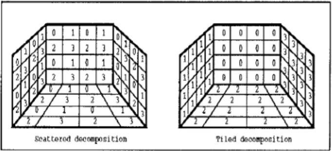
Two possible decomposition schemes are tiled and scot-
tered decompositions. In tiled decomposition, the neighbour-
ing patches are stored in t h e local memory of the same pro- cessor. This type of decomposition can be achieved in the following way: assuming t h a t the patches t h a t belong to the same object are supplied consecutively, the first N / P patches are stored in processor 0, t h e next N / P patches are allocated to processor 1, etc. At the end of the decomposi- tion, each processor stores almost equal number of patches in its local memory. In scattered decomposition, the neigh- bouring patches are stored in different processors, therefore the patches t h a t belong to a n object are shared by differ- ent processors. Scattered decomposition can be achieved in the following way: again assuming t h a t the neighbouring patches t h a t belong t o the same object are supplied consec- utively, the incoming patches are allocated t o the processors in a round-robin fashion. T h a t is, t h e first patch is allocated t o processor 0, the next t o processor 1, etc. When P patches are allocated, the next incoming patch is allocated t o proces- sor 0, and this process continues. When the decomposition
is completed, (N mod P ) processors store
[ N I P ]
patches, while the remaining processors store L N / P ] patches in their local memories. Figure 1 illustrates t h e scattered and tiled decomposition of a simple scene consisting of four faces of aroom. T h e numbers shown inside the patches indicate ids of the processors t h a t store them in their local memory.
Assuming t h a t neighbour patches require almost equal amount of computation for projection on different hemicubes, the scattered decomposition is expected t o pro- duce patch partitions requiring almost equal amount of com- putations in Phase 2. So, it can be expected t h a t the scat- tered decomposition achieves much better load balance in Phase 2 than the tiled decomposition.
I
Scattered decmposition Tiled &compositionFigure 1: Scattered and tiled decomposition schemes Communication overhead in this phase consists of two components: number of communications and volume of com- munications. Each concurrent communication step adds a fixed message set-up time overhead tsu t o the parallel algo- rithm. In medium grain multicomputers (e.g. Intel’s iPSC/2 hypercube) tsu is substantially greater than the transmis-
sion time t T R where t T R denotes the time taken for the
transmission of a single word. For example, tsu 5 5 0 p s e c
whereas ~ T R z 1.44psec per word in iPSC/P. Note that, communication of a n individual patch geometry involves the transmission of 3 floating point words for t h e vertices of the triangular patches, 3 words for their normal and one word for the patch id, adding t o 52 bytes (i.e.
TTR
= 13 ~ T R inEq. (5)). However, as seen in Eq. (5), the total number of concurrent communications a t each iteration is equal to the number of processors
P ,
whereas the total volume of com- munication is equal t o the number of patches N . Hence, the set-up time overhead can be considered as negligible for complex scenes ( N>>
P ) . Then, assuming a perfect load balance, efficiency of Phase 2 can be expressed as:since one iteration of the parallel algorithm is computation- ally equivalent t o P iterations of the sequential algorithm. Eq. (7) means t h a t projection of an individual patch onto a hemicube involves the communication of its geometry d a t a as an overhead. As is seen in Eq. (7), the overall efficiency of this phase only depends on the ratio T T R / T ~ R O for suffi- ciently large N I P . For example, efficiency is expected to in- crease with increasing patch areas and increasing hemicube resolution, since the granularity of a projection computation increases with these factors.
3.3 Phase 3: Form-Factor Computation
In this phase, each processor can concurrently compute the form-factor vector corresponding t o its shooting patch us- ing its local hemicube item-buffers constructed in the pre- vious phase. This phase requires no interprocessor commu- nication. Local form-factor vector computations involved in this phase require scanning all hemicube item-buffer entries. Hence, perfect load balance is easily achieved since each pro- cessor maintains a hemicube of equal resolution.
3.4
Phase
4: Contribution ComputationAt the end of Phase 3, each processor holds a form-factor vector corresponding t o its shooting patch. In this phase, each processor should compute the light contributions from all P shooting patches to its local patches. Hence, each processor needs all form-factor vectors. Thus, this phase necessitates global interprocessor communication since each processor owns only a single form-factor vector.
We introduce a vector notation for the sake of clarity of the presentation in this section. Let x k denote the k f h slice of a global vector
X
assigned to processork.
For example, each processork
can be considered as storing the k t h slice of the global array of records representing the whole patch geometry. Each processork
is responsible for computing the k t h slice ARk of the global contribution vector P R for updating the k t h slices Bk and ABk of the global ra- diosity and delta radiosity vectors B and A B , respectively. T h e notation used t o label the P distinct form-factor vectors maintained by P processors is slightly different. In this case, F’ denotes the form-factor vector computed by processore
and FL denotes the k t h slice of the local form-factor vector of processore.
As is seen in Eq. ( l ) , red, green and blue reflectiv- ity values r , ( r , g , b ) and the patch area A , of each patch
i
are needed as three ratios r , ( r , g , b ) / A , . Hence, eachprocessor computes three constants T ; ( T , g ,
b ) / A ;
for eachlocal patch i during the preprocessing. In vector nota- tion, each processor
k
can be considered as holding the k t h slice r k ( r , g , b )of
the global vector r ( r , g , b ) consisting of r t ( r , g , b ) / A , values. Thus, in vector notation, each proces- sork,
fork
= 0 , 1 ,...,
P-
1, is responsible for computingP-I
(9)
f = O
ARk(‘, g , 5) = rk(r, g , b ) x Uk(T! 9 , b ) (10) where A B h ( r , g , b ) and A: denote the delta radiosity val- ues and the area of the shooting patch of processor
e.
In Eq. ( l o ) , ” x denotes the element-by-element multipli- cation of two column vectors. Each processork
can con- currently update its local Bk andABk
vectors by simply performing local vector additions Bk = B+
ARk and ABk = ABk+
ARk for each color-band. h e s e concur- rent update operations do not necessitate any interprocessor communication. It is the parallel computation of the contri- bution vector ARk which requires global interaction.Note t h a t , the notation used t o label the U vectors is similar t o that of the F vectors since the P U vectors, of sizes N I P , are concurrently computed by P processors. T h a t is,
U i ( r ,
g, b ) represents the contribution vector of the shooting patch of processore
t o the local patches of pro- cessork
omitting the multiplications with the rI(r, g,b ) / A ,
coefficients. Hence, uk(7, g , b ) represents the total contri- bution vector of all P shooting patches t o the local patches of processor
k.
T h e first approach discussed in this work is very similar t o the implementation proposed by Chalmers and Paddon
[a].
In their implementation, each processore
broadcasts a packet consisting of the delta radiosities, area and the form- factor vector of its shooting patch. Each processor k, upon receiving a packet { AB,‘, A:, Fe }, computes a local contri- bution vector Uk(r, g, b) by performing a local scalar vector product for each color (Eq. (8)) and accumulates this vector t o its local Uk(7, g , b ) vector by performing a local vector addition operation (Eq. ( 9 ) ) . However, multiple broadcast operations are expensive and may cause excessive congestion in ring interconnection topologies. In this work, indicated packets are circulated in a synchronous manner, similar to the patch circulation discussed for Phase 2 . Between each successive communication steps of this form-factor vector circulation scheme, each processor concurrently performs the contribution vector accumulation computations (Eqs. (8) and (9)) corresponding t o its current packet. At the end ofP-1 concurrent communication steps, each processor
k
accu- mulates its total contribution vector uk(r, g ,a).
Then, each processork
can concurrently compute its local ARk(r, g, b )vector by performing local element-by-element vector mul- It is obvious t h a t perfect load balance in this phase can easily be achieved by mapping equal number of patches to each processor. Hence, the parallel complexity of Phase 2 using the form-factor vector circulation scheme, is:
tiplications (Eq. (10)).
T P ~ = ( P - 1)tsu
+
( P-
1 ) N t t r+
+ N T C O N T R
+
( N / P ) T U P D (11)Here, t t , is the time taken t o transmit a single floating point word, T C O N T R is the time taken t o compute and accumulate a single contribution value, and
TUPD
is the time taken t oupdate
a
single radiosity and delta radiosity value using the corresponding entry of a local u k vector.Note that, in this scheme, processors accumulate the contributions for their local patches during the circulation of form-factor vectors. Hence, as is also seen in Eq. ( l l ) , this scheme necessitates high volume of communication
( ( P - l ) N words) since whole form-factor vectors of sizes N
are concurrently communicated in each communication step. However, as is also seen in Eq. ( 8 ) , each processor IC needs only the kth slices (of sizes N I P ) of the form-factor vectors it receives during the circulation. T h a t is, form-factor cir- culation scheme involves the circulation of redundant infor- mation. In this work, we propose an efficient scheme which avoids this redundancy in the interprocessor communication. In the proposed scheme, partial contribution computation results ( Uk(r, g , b ) vectors of sizes N I P ) are circulated in- stead of the form-factor vectors ( of sizes N ) . Hence, each processor effectively accumulates the contributions of its lo- cal shooting patch t o all other processors' local patches dur- ing the circulation of the partial contribution computation results.
Figure 2 illustrates the pseudocode for the node program for the proposed contribution vector circulation scheme. This scheme also preserves the perfect load balance, if ex- actly equal number of patches is mapped t o each processor. Hence, the proposed circulation scheme reduces the overall parallel complexity of Phase 4 to
interiors consisting of objects such as chairs, tables, win- dows, lights in order t o represent a realistic 3D environment. Table 1: Effect of local and global shooting patch selection (in Phase 1) on convergence.
n
II umber of patch I1 T otal Execution #LOC Glo Dec LOC Glob Dec
Table 1 illustrates the effect of the local and global shoot- ing patch selection (in Phase 1) on the convergence of the parallel algorithm. As is seen in Table 1 , the global selection scheme decreases both the total number of shooting patch selections and the total parallel execution time significantly. Table 2: Effect of the decomposition scheme on the perfor- mance of the parallel hemicube production phase (Phase 2 ) . T P ~ ( P - 1 ) T . s ~
+
3 ( P - 1) ( N / P ) t t r+
+ P ( N / P ) T c o N T R
+
( N/P )TupD ( 1 2 ) T h e constant 3 appears as a coefficient in " t t r ' ' term sinceeach entry of individual U i vectors consists of 3 contribution values for 3 color-bands. Hence, the proposed circulation scheme reduces the total concurrent communication volume in Phase 4 by an asymptotical factor of
P / 3
forP
>
3. / * AB,(r,g,b) : d e l t a r a d i o s i t y o f l o c a l s h o o t i n g p a t c h ;A , : a r e a o f l o c a l s h o o t i n g p a t c h ; F : l o c a l f o r m - f a c t o r v e c t o r (of s i z e N ) ;
U ,
A R ,
B ,
AB
are local v e c t o r s ( o f size N / P ) ; */netlnode = (mynode + 1) mod P;
prevnode = (mynode
-
1) mod P ;k = mynode; U(T,g,b) = ABa(~,g,b)ApFpreVnode;
for i=l to P-1 do
s e n d U(r,g, 6) to p r o c e s s o r nectnode;
receive i n t o U(r,g, b ) from p r o c e s s o r prevnode;
U(T,g,b) E U(TrS,b) + ABs(r,g,b)As F ( k - i - 1 ) m o d P ;
endfor
AR(r,g,b) = r(r,g,b)
*
U(v,g,b); B(T,g, b) = B(T,g, b) + AR(rI g r 6) ;AB(r,g,b) = AB(r,s,b) + AR(r,g,b);
Figure 2: T h e contribution vector circulation scheme
4
Experimental Results
T h e proposed schemes are implemented on a ring-embedded Intel's iPSC/2 hypercube multicomputer. T h e form fac-
tors are computed using hemicubes of constant resolution 50 x 100 x 100. T h e proposed parallel algorithms are exper- imented for six different scenes with 522, 856, 1412, 3424, 5648 and 8352 patches. T h e test scenes are selected as house
Tiled Dec. 11 Scattered Dec. emicube prod seq Hemicube 11 H
N time P Prod. I II Prod. I
U
(secs4
11
6 . 6 4 61
0 . 6 5 211
4 . 8 9 6I
0.885 5648 17.335 8 11 3.680 I 0 . 5 8 9 I] 2.496 I 0.868i f i II 3 nfin I n 534 11 1 377 I n 848
Table 2 shows the effect of the decomposition scheme on the performance of the hemicube production phase. Paral- lel timings
(TPAR)
in Table 2 denote the parallel hemicube production time per shooting patch. These timings are computed as the execution time of P concurrent hemicube productions divided byP
sinceP
hemicubes are concur- rently produced for P shooting patches in a single itera- tion of Phase 2. Sequential timings ( T S E Q ) in Table 2 de- note the sequential execution time of a single hemicube pro- duction. Efficiency values in Table 2 are computed usingEf f = T s E Q / ( P T P A R ) . Efficiency values are considered as qualitative measures for comparison of the decomposition schemes. As is seen in Table 2, scattered decomposition al-
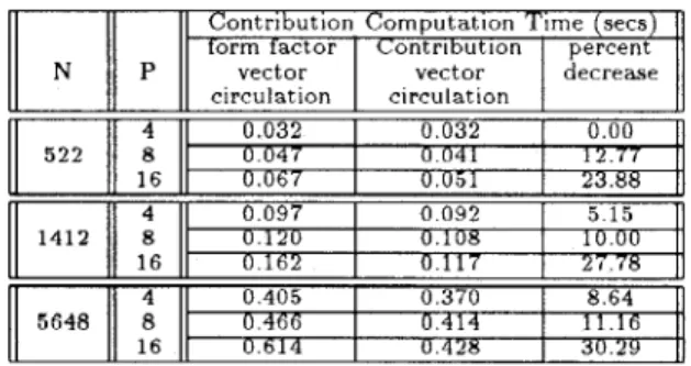
ways achieves better load balance than tiled decomposition. Table 3 illustrates the execution times of the distributed contribution vector computation during a single iteration of the parallel algorithm. T h e last column of Table 3 illus- trates the percent decrease
in
the execution times obtainedby using the c o n t r i b u t i o n v e c t o r c i r c u l a t i o n i n s t e a d of form-
factor vector circulation. Note that, the advantage of the contribution vector circulation over the form-factor circula- tion increases with increasing P as is expected.
Table 3: Effect of the circulation scheme on the perfor- mance of the parallel light contribution computation phase (Phase 4).
Contribution Computation Time (secs) form factor Contribution percent
N P vector vector decrease circulation circulation 5 2 2 8 0 047 0 041 1 2 7 7
.
4 0 032 0 032 0 00 16 0 067 U 651 23 88 4 0 097 0 092 5 1 5 1412 8 U 1 2 U 0 1 0 8 10 00 16 0 162 0 117 2 7 7 8 . 4 0 405 0 370 8 64 5648 8 0 4 6 6 I 0 414I
! 1 ? 6 16 0 6 1 4 I 0 428Figure 3 illustrates the overall efficiency curves of the parallel progressive radiosity algorithm. Note t h a t , global shooting patch selection, scattered decomposition and con- tribution vector circulation schemes are used in Phases 1, 2 and 4, respectively, in order to obtain utmost parallel per- formance. As is seen in Fig. 3, efficiency decreases with increasing
P
for a fixed N . There are two main reasons for this decrease in the efficiency. T h e first one is the slight increase in the load imbalance of the parallel hemicnbe pro- duction phase with increasingP .
T h e second, and the more crucial reason is the modification introduced t o the original sequential algorithm for the sake of parallelization. As is discussed in Section 3, this modification increases the total number of shooting patch selections required for convergence in comparison with the sequential algorithm.1-00 0.90 0.60
i
0.70 0.80 0.60 0.40-
P-2 A ...*
p-4 Q - - E I P - S *r -*
P-i 6 0 34m 5400 7400 Numb-r of patehe*Figure 3: Overall efficiency of the parallel solution
5
Conclusion and
Future
Work
In this paper, a p a r a l l e l progressive radiosity algorithm is proposed for ring-connected multicomputers and imple- mented on a ring-embedded Intel’s iPSC/2 hypercube com- puter. T h e proposed parallel algorithm utilizes a syn- chronous scheme based on static task assignment. Exper- imental results show t h a t scattered decomposition of the scene geometry yields adequate load balance during paral- lel hemicube production computations. Circulation of par- tial contribution results instead of the form-factor vectors is proved t o decrease the total volume of concurrent comniuni- cation by an asymptotical factor. Experiniental results show t h a t global shooting patch selection yields much better per-
formance than local shooting patch selection as is expected. Modification of the original progressive radiosity for the sake of efficient parallelization is experimentally found t o yield good results. T h e performance of this modification is expected t o increase with decreasing tolerance values which necessitate larger number of iterations for convergence.
6
Acknowledgement
We would like t o acknowledge Guy Moreillon for his house interior model. T h e house d a t a is available through anony- mous ft p a t site gondw ana. ecr. mu. oz. au.
References
[l] Baum, Daniel R., James M. Winget, “Real Time Ra- diosity Through Parallel Processing and Hardware Ac- celaration”, Proceedings of t h e 1990 Symposium on In- teractive 3D Computer Graphics, In Computer Graph- ics, vo1.24, No.& 1990, pp 67-75.
[2] Chalmers, Alan G., Derek J. Paddon, “Parallel Pro- cessing of Progressive Refinement Radiosity Methods”, Proceedings of the Second Eurographics Workshop on Rendering, Barcelona, Spain, May 1991.
[3] Cohen, Micheal
F.,
Donald P. Greenberg, “The Hemi- Cube: A Radiosity Solution for Complex Environ- m e n t ~ ’ ~ , Proceedings of SIGGRAPH ’85 (San Fransisco, California, July 1985). In Computer Graphics, Vo1.19, [4] Cohen, MichaelF.,
Shenchang Eric Chen, JohnR.
Wal-lace, Donald P. Greenberg, “A Progressive Refinement Approach t o Fast Radiosity Image Generation”, Pro- ceedings of SIGGRAPH ’88 (Atlanta, Georgia, August 1988). In Computer Graphics, V01.22, No.4, 1988, pp [5] Drucker, Steven
M.
and Peter Schroder, “Fast Radios- ity Using a Data Parallel Architecture”, Proceedings of the Third Eurographics Workshop on Rendering, Bris- tol, England, May 1992, pp 247-258.[6] Feda, Martin, Werner Purgathofer, “Progressive Re- finement Radiosity on a Transputer Network”, Proceed- ings of the Second Eurographics Workshop on Render- ing, Barcelona, Spain, May 1991.
[7] Goral, Cindy M., Kenneth E. Torrance, Donald P.
Greenberg, Bennett Battaile, “Modelling the Interac- tion of Light Between Diffuse Surfaces”, Proceedings of SIGGRAPH ’84 (Boston, Massachusetts). In Computer Graphics, Vo1.18, No.3, July 1984, pp 213-222.
[8] Puech, Claude, Francois Sillion, Cristophe Vedel, “Im- proving Interaction with Radiosity-based Lighting Sim- ulation Programs”, Proceedings of the 1990 Symposium on Interactive 3D Computer Graphics, In Computer Graphics, vo1.24, No.2, 1990, pp 51-57.
[9] Recker, Rodney J, David W. George, Donald P. Green- berg, “Acceleration Techniques for Progressive Refine- ment Radiosity”
,
Proceedings of t h e 1990 Symposium on Interactive 3D Computer Graphics, In Computer Graphics, vo1.24, No.2, 1990, p p 59-66.[ l o ] Varshney, Amitabh and J a n F. Prins, “An Environment Projection Approach t o Radiosity for Mesh-Connected Computers”, Proceedings of the Third Eurographics Workshop on Rendering, Bristol, England, May 1992, NO.3, 1985, pp 31-40.
75-84.