A Comparative Real-Time Speed Control of PMSM with Fuzzy Logic and ANN Based Vector Controller
Ezgi Güney 1*, Serap Karagöl 2, Memnun Demir 3 1 Sinop University; [email protected]
2 Ondokuz Mayıs University; [email protected] 3 Sinop University; [email protected]
* Ezgi Güney; [email protected]; Tel. +90 505 593 92 56
Received Date: 29/03/2019 Accepted Date: 25/06/2019 ABSTRACT
This paper presents, analyzed real-time speed control of Permanent Magnet Synchronous Motor (PMSM) under constant load by using Fuzzy Logic (FL) controller and recurrent Artificial Neural Network (ANN) controller. A closed loop PMSM drive system is improved using the mathematical model of the PMSM in Matlab / Simulink. Two types of controllers are used; the first controller is the real-time FL controller and the second controller is a real-time recurrent ANN controller in terms of smoother speed response. Whole drive systems are simulated in Matlab/Simulink program. The simulation results show that the focused ANN controller produce considerable control performance compare to the FL controller on controlling speed reference variations.
Keywords: PMSM; Artificial neural network; Fuzzy logic, Real-time control
SMSM'nin Bulanık Mantık ve YSA Tabanlı Vektör Kontrol Yöntemi ile Karşılaştırmalı Gerçek Zamanlı Hız Kontrolü
ÖZET
Bu çalışmada, Bulanık Mantık (BM) ve tekrarlayan Yapay Sinir Ağı (YSA) kontrol ünitesi kullanılarak Sabit Mıknatıslı Senkron Motorunun (SMSM)sabit yük altında gerçek zamanlı hız kontrolü sunulmaktadır. SMSM’ nin matematiksel modeli kullanılarak Matlab / Simulink’te kapalı çevrim PMSM tahrik sistemi geliştirilmiştir. İki tip kontrolör kullanılmıştır; birinci denetleyici, gerçek zamanlı BM denetleyicisi ve ikinci denetleyici, daha yumuşak hız tepkisi açısından gerçek zamanlı bir tekrarlayan YSA denetleyicisidir. Tüm tahrik sistemleri Matlab / Simulink programında simüle edilmiştir. Simülasyon sonuçları, odaklanılan YSA kontrolörünün, hız referansı değişikliklerini kontrol etmede BM kontrolörüne kıyasla önemli kontrol performansı sağladığını göstermektedir. Anahtar Kelimeler: SMSM, yapay sinir ağları, bulanık mantık, gerçek zamanlı kontrol.
1. INTRODUCTION
Permanent magnet synchronous motor (PMSM) drives have been extensively used in industrial applications such as electrical vehicles, robotic automation, medical instruments, aircraft, especially in industrial servo applications (Shiny et al., 2014; Kumari, 2015; Asri et al., 2017) due to their advantages over other motors, which including high efficiency, high air gap flux density, small inertia, high power factor, high torque to inertia ratio and compactness (Plangklang et al., 2013; Birou et al., 2014; Habbi et al., 2016).
PMSM speed control is not easy because of the parameter and load torque variations. Due to the stimulation is ensured with a permanent magnet instead of a field winding, using DC supply and slip ring decrease the motor losses, maintenance and complexity in PMSM (Plangklang, 2013). To control the SMSM, V/f control, field oriented control (FOC) and direct torque control methods are used (Stulrajter et al., 2007; Xu et al., 2013). From among
these methods, FOC techniques, which are extensively used in PMSM drives, converts the motor equations into a coordinate system so that rotates in synchronism with the rotor flux vector. With the aid of the FOC or vector control of PMSM drive, it is become easier to separate the torque and flux producing components of stator currents and controlling the motor like a DC motor. This technique allows fast dynamic response, less torque ripple and smooth starting for PMSM (Madhu and Mathew, 2013). FOCs implemented in various ways such as Proportional-Integral (PI), Artificial Neural Networks (ANNs) and Fuzzy Logic (FL) (Hasanien, 2011; Pewmaikam, 2012; Rajasekhar et al., 2014; Reddy et al., 2016).
PI controller is generally used in the industry because of their ease in structure and implementation, good steady state accuracy, quick control and low costs. A PI resonant controller used for the sine-shaped test current (Ebersberger et al., 2013) and this paper is modified in (Seilmeier and Piepenbreier, 2014) that it directly provides a dc error signal without need for further demodulation and delay compensation. PI controller can even be used together with an optimization algorithm to improve the efficiency of PMSM. A typical PI controller with an estimator of zero-delay current (ZDC) value is enhanced for field oriented control of PMSM (Jarzebowicz et al., 2015). The ZDC estimation allows for selecting substantially higher controller gain. PMSM based on optimizing the parameters of the speed and torque PI-Controllers, using Krill Herd (KH) algorithm is presented and software show a satisfactory performance of the proposed controller against load disturbances as well as robustness against machine parameters' variations (Younesi and Tohid, 2015). In another work, it is proposed a combination of the Model Conclusiın Adaptive System (MRAS) scheme to estimate the speed information of the PMSM and the proportional integral (PI) scheme with the particle swarm optimization (PSO) to tune the PI gains used in the speed control of the PMSM (Abd Samat et al., 2016). However, it is not easy to determine proportional-integral parameters truly, so it is difficult to system to be stable and robust (Habbi and Sara, 2016).
FL controller has increasingly implemented in today’s technologies for developing complicated control systems. A fuzzy logic based speed and current control of FOC of a PMSM is discussed and simulation results show the validity of proposed controllers (Mishra et al., 2015). In another work (Leu et al., 2011) fuzzy sliding mode speed controller for PMSM with load torque observer is proposed. Simulation and experimental results demonstrated that the proposed control system can both attenuate the chattering to the extent of other control methods and give a better transient performance in comparison with the non-fuzzy sliding mode controller. For speed control of PMSM, self-tuning non-fuzzy-PID controller and PID controller is designed to apply to speed control unit of PMSM. According to obtained simulation results, it is observed that Self-tuning fuzzy-PID controller provides better speed response than PID controller (Mustafa et al., 2015). For the sensorless speed control of PMSM, a fuzzy speed controller is proposed using Model Reference Adaptive System (MRAS) (Abdelnaby, 2015). When the load torque changes suddenly this algorithm decreases the rise time to reach the speed reference. Fuzzy logic control system is based on human knowledge and experience and is used to model any system characteristics by a set of fuzzy values and rules that each rule base results in a mathematical function to generate the possible performance. However, the determination of membership functions and control rules is an important problem in a design, which needs designer’s experiences to achieve convincing membership functions and control rules. However, FL based controllers are insufficient to include any learning previously acquired about the dynamics of the system (Murat and İbrahim, 2011). Also, FLC has disadvantage because it based on the designer experience to design the rule base, input and output membership functions, which makes the design procedure complicated (Wibowo and Jeong, 2013).
Artificial intelligence based methods have a great robustness since its design is independent of mathematical models of the controlled system. A new nonlinear and adaptive backstepping speed and current control scheme in the sense of Lyapunov stability theory is developed for the PMSM (Karabacak and Eskikurt, 2011). The proposed method ensures that the speed and current tracking errors converge to zero asymptotically. A new nonlinear and full adaptive backstepping speed tracking control scheme is developed for an uncertain PMSM (Karabacak and Eskikurt, 2012; Coban, 2017). At the same time, real time implementation of these methods is very difficult due to its heavy computational effort and algorithm complexity.
Among adaptive nonlinear control methods in the literature, ANNs are very powerful in nonlinear systems. Moreover, ANN controller achieves outstanding performance at the expense of a heavy computation. ANN has many superiorities such as adaptation to unknown situations, modelling complex functions, ease of use, need of little user domain specific expertise at the same time. Although ANN have some disadvantages such as wide training time, wide number of neurons and hidden layers to overcome to complex problems (Thampatty and Raj, 2015). Real time recurrent learning algorithm is one of the most suitable architecture for real-time application.
In order to deal with the heavy computational effort and algorithm complexity, a new nonlinear and adaptive real time recurrent learning ANN and FL controller designs are proposed and compare the performances design in this study. The paper is organized as follows. Section 2 includes PMSM's construction and mathematical equation. Section 3 deals with FL and ANN controller design to control of PMSM. Section 4 evaluates simulation results. Section 5 includes conclusion.
2. MATERIAL and METHOD
2.1 PMSM’s construction and mathematical model 2.1.1 PMSM’s construction
The PMSM is a constant-speed machine that rotates at a speed which depends on the source frequency and the number of poles. The PMSM structure; traditionally consists of three-phase windings in the stator and permanent magnets mounted on the rotor surface (surface PMSM). Sometimes the magnets are placed in the rotor (interior PMSM) in a rotor type. To create a constant magnetic field, permanent magnets are placed in the steel rotor. The stator windings are connected to an AC supply to produce a rotating magnetic field. The rotor is fed up with a DC supply. Due to the motor dynamics are nonlinear, multivariable and critical parameters are uncertain, controlling of these motors is reasonably complex. To obtain high efficient control, Field Oriented Control / Vector Control (FOC) approach is used. The new approach is based on controlling the magnitudes and angles of the space vectors. FOC is provides an effective performance in electrical drives. In addition, vector control eliminates nearly all the disadvantages of constant V/f control (Stulrajter et al., 2007).
2.1.2 PMSM’s mathematical model
The modeling of the dynamic behavior of the PMSM in the three-axis system is possible with time-varying coefficient differential equations and a very complicated model structure arises. For this reason, the PMSM mathematical model is usually explained with the rotating reference frame (d-q reference frame) equations. Vector control is a method to control the motor on the two-phase (d-q) coordinate system instead of the three-phase (u, v, w) coordinate system. The d-axis is set in the direction of the magnetic flux (N pole) of the
permanent magnet and the q-axis is set in the direction, which progresses, by 90 degrees (electrical) in the forward direction of the angle θ from the d-axis. Due to the absence of rotor winding current, only stator current can be controlled in an PMSM drive. In many similar studies, researchers assumed the id current to be '0' on the assumption that it made control easier (Qutubuddin and Yadaiah, 2017). Hence, we assumed that in the current controller that id current is zero. The mathematical model of PMSM in the d-q axis frame can be written by the following equations.
[𝑣𝑣𝑑 𝑞] = [ 𝑅𝑠+ 𝑝𝐿𝑑 −𝜔𝐿𝑞 𝜔𝐿𝑑 𝑅𝑠+ 𝑝𝐿𝑞] [ 𝑖𝑑 𝑖𝑞] + [ 0 𝜔𝜓𝑎], (1)
𝑣𝑑 and 𝑣𝑞 are the d, q axis voltages, 𝑖𝑑 and 𝑖𝑞 are the d, q axis stator currents, 𝐿𝑑 and 𝐿𝑞 are the d, q axis inductances, 𝑝 is the differential operator, 𝜓𝑎 is the flux linkage due to
permanent inductance while 𝜔 is the angular speed and 𝑅𝑠 is the stator resistance the stator.
The generated torque given in Equation (2) is obtained by the sum of the magnet torque and the reluctance torque (Chaoui and Pierre, 2012).
𝑇 = 𝑃𝑛{𝜓𝑎𝑖𝑞+ (𝐿𝑑− 𝐿𝑞)𝑖𝑑𝑖𝑞}, (2) T is the motor torque and 𝑃𝑛 is the pole pair number. The equation for the motor dynamics is;
𝑇𝑒= 𝑇𝐿+ 𝐵𝜔𝑟+ 𝐽𝑝𝜔𝑟, (3)
𝑇𝐿 is the load torque, B is the damping coefficient, 𝜔𝑟 is the rotor speed, and J is the moment of inertia. There is no variation among the d-axis and q-axis inductances in the PMSM and due to the reluctance torque is 0.
The total torque is proportional to the q-axis current. Hence, the q-axis current is called torque current. In two-phase (d, q) phase coordinate, the d-axis flux is sum of permanent magnet flux and flux generated by d-axis current. The d-axis current is called as excitation current, owing to the equivalent rotating stator flux is controlled by d-axis current. The (d-q) coordinate transformation is performed with the Park transform by using a,b,c variables as defined in Equation (4): [ 𝑣𝑞 𝑣𝑑 𝑣0 ] =2 3[
cos (𝜃) cos (𝜃 − 2𝜋 3⁄ ) cos (𝜃 + 2𝜋 3⁄ ) sin (𝜃) sin (𝜃 − 2𝜋 3⁄ ) sin (𝜃 + 2𝜋 3⁄ )
1 2⁄ 1 2⁄ 1 2⁄ ] ∗ [ 𝑣𝑎 𝑣𝑏 𝑣𝑐 ], (4)
a, b, c variables are obtained from the d, q variables through the inverse of the Park transform defined in Equation (5): [ 𝑣𝑎 𝑣𝑏 𝑣𝑐 ] = [ cos (𝜃) sin (𝜃) 1 cos (𝜃 − 2𝜋 3⁄ ) sin (𝜃 − 2𝜋 3⁄ ) 1 cos (𝜃 + 2𝜋 3⁄ ) sin (𝜃 + 2𝜋 3⁄ ) 1 ] ∗ [ 𝑣𝑞 𝑣𝑑 𝑣0 ], (5)
Based on Equation (4) and (5), it can be considered that alternate current flowing in the stationary three-phase stator is equivalent to direct current flowing in the two-phase stator rotating synchronously with the permanent magnet operating as a rotor.
2.2 Controller Design
2.2.1 Real Time Recurrent ANN Structure
The real time recurrent learning algorithm is a successful learning algorithms due to the torage required and computation time on each step are free of time and entirely determined by the size of the network. In addition, it is not required to know prior knowledge of the temporal structure of the task being learned. In this algorithm, the gradient of errors is propagated forward in time rather than backward in time. Hence, it is particularly suitable for online training of recurrent neural networks (Jayalakshmi and Santhakumaran, 2011). The recurrent neural network architecture is a dynamic system, which is capable of storing temporal information (Thampatty and Raj, 2015). The outputs of recurrent neural network are not only a function of the current inputs, but also a function of previous inputs and outputs. In the first run, the network assigns weights randomly (Goh and Mandic, 2004; Guney et al., 2017). The architecture of ANN composes of an input layer, ten neurons in processing layer and an output layer, which is given in Figure 1.
Figure 1. System multilayer feedforward-backpropagation ANN structure.
Once rotor performs the first round, the network starts to learn. For the network input knowledge, rotor speed value ω and reference speed value ω* are used. Rotor speed value is send by the system developed. The reference speed is determined by user. The network generates error value using these two inputs and uses it for network training. The error is propagated backwards to modify the network weights. When the error reaches a minimum threshold, this process stops. The error value is passed to the ANN controller and the iq* is determined (Wilamowski, 2009).
Due to the ANN's non-linearity characteristic, the data are normalized in the range [0 - 1] with the Min-Max Normalization method. In developed simulation model, the data range for X_min - X_max is determined as 0-200 and scaled according to the Equation (6).
𝑋𝑛=
𝑋0−𝑋𝑚𝑖𝑛
𝑋𝑚𝑎𝑥−𝑋𝑚𝑖𝑛, (6)
Where X_n is new value and X_0 is current value for variable X, X_min and X_max are minimum and maximum values in data set (Guney et al., 2017).
2.2.2 Recurrent ANN Controller
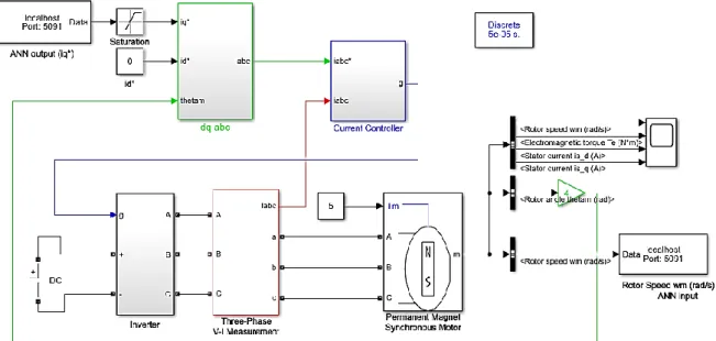
The simulation studies of PMSM with ANN speed control were performed in Matlab/Simulink environment using equations related to mathematical model of PMSM given in Section II. The implemented simulink model of PMSM with drive circuit using Matlab/Simulink software is given in Figure 2. The PMSM speed control system basically composed of PMSM, DC power supply, universal bridge, three-phase voltage inverter module, three phase V-I measurement and sub-system blocks. It is mentioned in Section III that the error value obtained from the reference speed ω* and the instantaneous speed ω is applied to the input of the ANN controller input.
Figure 2. The PMSM speed control system’s simulation model with ANN based Vector Control. As an output of the ANN controller, the iq* reference current value is obtained. Due to the study of motor during transient and steady state, the dynamic d-q coordinate system is used. The d-q variables are converted to three phase currents iabc* by using Inverse Parks Transformation (Madhu and Mathew, 2013). The contents of dq-abc’s Matlab/Simulink simulation block is given in Figure 3.
Figure 3. The dq-abc's Matlab/Simulink simulation block.
The current controller block generates the drive signals to be applied to the switches of the voltage source inverter to obtain the reference voltages. The current controller simulation block used in switching the inverter is given in Figure 4.
Figure 4. Current Controller Matlab/Simulink simulation block.
In Figure 5, the content of the voltage-source inverter Matlab/Simulink simulation block used to control PMSM is given.
Figure 5. The contents of the inverter Matlab/Simulink simulation block. 2.2.3 Fuzzy Logic Controller
Fuzzy systems define the set and rules by associating all of the inputs with all of the outputs. Therefore, the working structure of fuzzy systems is similar to the way a mathematical reason-result function works. Fuzzy logic controller consists of four main units: fuzzifier, rules, inference engine, and defuzzifier. The fuzzy logic process is clarified as follows: In first step, which is fuzzification, a set of input data are gathered and converted to a fuzzy set using fuzzy linguistic variables, fuzzy linguistic terms and membership functions. Then, a deduction is made based on a set of rules. Finally, the fuzzy output is mapped to a new output using the membership functions, in the defuzzification step (Shiny et al., 2014). The structure of the fuzzy controller, which is chosen as the controller of the system is given in Figure 6.
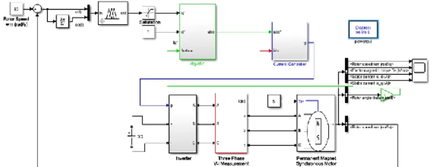
Figure 6 The PMSM speed control system’s simulation model with Fuzzy Logic based Vector Control.
In this paper, there are two inputs of the fuzzy logic controller: e(t) speed error and ce(t) change in speed error. iq*, the output variable, is also provided. Generally, the phase current (iabc*) are controlled by the speed controller that usually known as q axis current (iq and id). The next step is choosing the membership function, which is modelled in Equation (7) and (8).
𝑒(𝑡) = 𝜔∗− 𝜔, (7)
𝑐𝑒(𝑡) = 𝑒(𝑡) − 𝑒(𝑡 − 1 (8)
Where ω* is the speed reference, ωis the real speed, e(t) is the speed error and ce(t) is change
in error. FL controller is created with two inputs and single output in Figure 7.
(a)
(b)
(c)
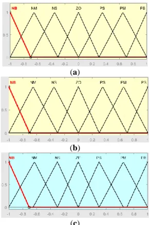
Figure 7. The membership function: (a) Error; (b) Derivative of error; (c) Output.
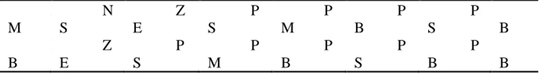
The fuzzy set used the triangular membership function to reduce calculation for on-line operation (Abd Samat et al., 2016). Table 1 shows the data based on the 49 rule base for the decision making unit.
Table 1. Rule base for speed control
e /ce N B N M N S Z E P S P M P B N B N S N S N S N B N M N S Z E N M N S N S N B N M N S Z E P S N S N S N B N M N S Z E P S P M Z E N B N M N S Z E P S P M P B P S N M N S Z E P S P M P B P S
P M N S Z E P S P M P B P S P B P B Z E P S P M P B P S P B P B
For the PMSM speed control, Mamdani type fuzzy logic controller is preferred. Fuzzy numbers are calculated based on (t) and ce(t) using the membership function of Figure 7. Each universe of discourse is divided into seven fuzzy sets: NB (negative big), NM (negative medium), NS (negative small), ZE (zero), PS (positive small), PM (positive medium) and PB (positive big). Each fuzzy variable is a member of the subsets with a degree of membership varying between [-1, 1]. Then, e(t) and ce(t) are processed by an inference engine that realizes a set of control rules contained in (7x7) rule bases. Because of the control rules are formulated using the knowledge of the PMSM behavior, the max-min inference algorithm is used (Shiny et al., 2014). In the defuzzification stage, inference engine output variable is converted into a new value by using centroid defuzzification algorithm.
3. RESULTS and DISCUSSION
The simulation was developed by using a Matlab/Simulink. The result of speed, torque, and current was observed and analyzed. The motor parameter that been used in this project is shown in Table 2.
Table 2. This PMSM parameters.
Description Title 2 Title 3 Motor Inertia J 0.0027 kg.m2
d-axis Inductance 𝐿𝑞 0.0085 H
q-axis Inductance 𝐿𝑑 0.0085 H
Armature Resistance 𝑅𝑎 0.2 Ω
Number of Pole Pair 𝑃𝑛 8
Viscous Damping 𝐹 0.000492 Nms
Several tests have been performed for variable speed values to evaluate the performances of the proposed FL and ANN controller based vector control of PMSM. Some of the sample results, which composed of speed, torque and current, are presented in this paper. The characteristic of the system is observed under different cases which is motor is started from 0 rad/s with constant torque and varied speed. The reference speed is firstly given a speed of 80 rad/s, which is then increased to 120 rad/s and 160 rad/s in same load torque.
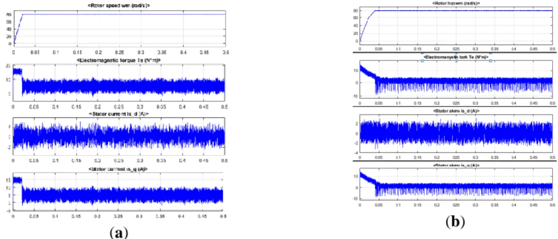
Simulation results are given when the motor is run under the load torque condition at rated of 5 Nm with constant speed of 80 rpm as shown in Figure 8 (a) and Figure 8 (b).
(a) (b)
Figure 8. Simulation results for 80 rad/s reference speed and 5 N.m load condition (rotor speed, electromagnetic torque, stator current id and stator current iq) for: (a) FL controller; (b) ANN controller.
Speed increases linearly from 0 to 80 rad/s and remains steady after 0.04 second in ANN controller when remains steady after 0.021 seconds in FL controller. This is because ANN uses random weights for the first time to run. Both the steady state speed is the same as that of the commanded reference speed, which validates the simulation result. In addition, it is seen that id current is constantly zero; iq current is linearly changed with moment.
Simulation results are given when the motor is run under the load torque condition at rated of 5 Nm with constant speed of 120 rpm as shown in Figure 9 (a) and Figure 9 (b). Speed increases linearly from 0 to 120 rad/s and remains steady after 0.029 second in ANN controller when remains steady after 0.031 seconds in FL controller. From these figures, it can be seen that the motors reach reference speed shorter time with ANN controller, because, as explained before, network is learning gradually as it goes on training.
(a) (b)
Figure 9. Simulation results for 120 rad/s reference speed and 5 N.m load condition (rotor speed, electromagnetic torque, stator current id and stator current iq) for: (a) FL controller; (b) ANN controller.
Simulation results are given when the motor is run under the load torque condition at rated of 5 Nm with constant speed of 160 rpm as shown in Figure 10 (a) and Figure 10 (b).
Figure 10. Simulation results for 160 rad/s reference speed and 5 N.m load condition (rotor speed, electromagnetic torque, stator current id and stator current iq) for: (a) FL controller; (b) ANN controller.
5. CONCLUSION
In this paper, we present a comparison between new nonlinear and adaptive real-time recurrent ANN controller and real-time FL controller for the PMSM speed and current control. The system block is designed in Matlab/Simulink environment using d-q coordinate for different feedback speeds. Different reference speeds and the same load torque variation were tested in the simulation and results were observed for both of the control methods. The system results are given in Figure 8, 9, 10. It is concluded that using real-time recurrent ANN controller is better than FL controller. As the figures are examined, recurrent ANN controller can ensure the speed at desired values regardless of change of speed. It is noted that in order to achieve high performance in a real time recurrent controller, it is very important for the system performance to operate the network multiple times. The advantage of this study over other control algorithms is the ability to detect instantaneous changes in the system in real time with real-time learning and keep system performance at the desired level according to new situations. In addition, with this network structure developed, the problem of long training time, which is a disadvantage of ANN's control process, has been solved. Since the developed network structure is capable of learning in a short period of time, it is considered that doing the same work on the real system in future works will enhance reliability.
REFERENCES
Abd Samat, A. A., Ishak, D., Omar, A. M., Iqbal, S., & Razak, M. A. (2016). A New Speed Sensorless Field Oriented Controller for PMSM Based on MRAS and PSO. Journal of Electrıcal Systems, 12(3), 565-+.
Abdelnaby, G. F., Dakrory, T. A., Arafa, S. H., & Ramdan, S. G. (2015). Sensorless Field Oriented Control of Permanent Magnet Synchronous Motor. International Journal of Current Engineering and Technology, 5(1).
Asri, A., Samat, A., & Fazli, M. N. (2017). Regular paper Speed Control Design of Permanent Magnet Synchronous Motor using Takagi-Sugeno Fuzzy Logic Control. J. Electrical Systems, 13(4), 689-695.
Birou, I. M., Rusu, C. C., Pavel, S. G., & Maier, V. (2014, October). Real-time robust controlled driving system with permanent-magnet synchronous motor. In 2014 International Conference and Exposition on Electrical and Power Engineering (EPE), 921-926.
Coban, R. (2017). Backstepping sliding mode tracking controller design and experimental application to an electromechanical system. Journal of Control Engineering and Applied Informatics, 19(3), 88-96.
Ebersberger, S., Seilmeier, M., & Piepenbreier, B. (2013, October). Flatness based sensorless control of PMSM using test current signal injection and compensation for differential cross-coupling inductances at standstill and low speed range. In 2013 IEEE International Symposium on Sensorless Control for Electrical Drives and Predictive Control of Electrical Drives and Power Electronics(SLED/PRECEDE), 1-7.
Goh, S. L., & Mandic, D. P. (2004). A complex-valued RTRL algorithm for recurrent neural networks. Neural computation, 16(12), 2699-2713.
Guney, E., Dursun, M., & Demir, M. (2017, January). Artificial neural network based real time speed control of a linear tubular permanent magnet direct current motor. In 2017
International Conference on Control, Automation and Diagnosis (ICCAD) (pp. 540-544).
Habbi, H. M. D., & Rashed, S. T. (2016). PI and Fuzzy Speed Controllers for PM Synchronous Motor Drive. International Journal of Computer Applications, 149(1). Hasanien, H. M. (2011). FPGA implementation of adaptive ANN controller for speed
regulation of permanent magnet stepper motor drives. Energy Conversion and Management, 52(2), 1252-1257.
Jarzebowicz, L., Opalinski, A., & Cisek, M. (2015). Improving control dynamics of PMSM drive by estimating zero-delay current value. Elektronika ir Elektrotechnika, 21(2), 20-23.
Jayalakshmi, T., & Santhakumaran, A. (2011). Statistical normalization and back propagation for classification. International Journal of Computer Theory and Engineering, 3(1), 1793-8201.
Karabacak, M., & Eskikurt, H. I. (2011). Speed and current regulation of a permanent magnet synchronous motor via nonlinear and adaptive backstepping control. Mathematical and Computer Modelling, 53(9-10), 2015-2030.
Karabacak, M., & Eskikurt, H. I. (2012). Design, modelling and simulation of a new nonlinear and full adaptive backstepping speed tracking controller for uncertain PMSM. Applied Mathematical Modelling, 36(11), 5199-5213.
Kumari, K. (2015). Field oriented control of PMSM with model reference adaptive control using Fuzzy-PI controller, International Journal of Circuit Theory and Applications, 8(1), 96-108.
Leu, V. Q., Choi, H. H., & Jung, J. W. (2011). Fuzzy sliding mode speed controller for PM synchronous motors with a load torque observer. IEEE Transactions on Power Electronics, 27(3), 1530-1539.
Madhu, R. K., & Mathew, A. (2013). Matlab/simulink model of field oriented control of pmsm drive using space vectors. International Journal of Advances in Engineering & Technology, 6(3), 1355.
Mishra, A., Mahajan, V., Agarwal, P., & Srivastava, S. P. (2012, December). Fuzzy logic based speed and current control of vector controlled PMSM drive. In 2012 2nd International Conference on Power, Control and Embedded Systems (pp. 1-6).
Pewmaikam, C., Srisertpol, J., & Khajorntraidet, C. (2012). Adaptive fuzzy logic compensator for permanent magnet synchronous motor torque control system. International Journal of Modeling and Optimization, 2(2), 141.
Plangklang, B., Kantawong, S., & Noppakant, A. (2013). Study of generator mode on permanent magnet synchronous motor (PMSM) for application on elevator energy regenerative unit (EERU). Energy Procedia, 34, 382-389.
Qutubuddin, M. D., & Yadaiah, N. (2017). Modeling and implementation of brain emotional controller for Permanent Magnet Synchronous motor drive. Engineering Applications of Artificial Intelligence, 60, 193-203.
Rajasekhar, A., Jatoth, R. K., & Abraham, A. (2014). Design of intelligent PID/PIλDμ speed controller for chopper fed DC motor drive using opposition based artificial bee colony algorithm. Engineering Applications of Artificial Intelligence, 29, 13-32.
Reddy, B. L., Anjaiah, U., & Rao, T. S. (2016). A Closed Loop Speed Control of PMSM Drive Using Fuzzy Logic Controller. ImperialJournal of Interdisciplinary Research (IJIR), 2(6).
Seilmeier, M., & Piepenbreier, B. (2014). Sensorless control of PMSM for the whole speed range using two-degree-of-freedom current control and HF test current injection for low-speed range. IEEE Transactions on Power Electronics, 30(8), 4394-4403.
Shiny, J., Ragulkumar, M. and Govindarajulu, R. (2014). Adaptive fuzzy logic based speed control of permanent magnet synchronous motor using FPGA, International Journal of Emerging Trends in Science and Technology, 1(3), 393-398.
Štulrajter, M., Hrabovcova, V., & Franko, M. (2007). Permanent magnets synchronous motor control theory. Journal of electrical engineering, 58(2), 79-84.
Thampatty, K. S., & Raj, P. R. (2015). An Adaptive RTRL Based Neurocontroller for Damping Power System Oscillations. International Journal of Applied, 4(1), 1-12. Wibowo, W. K., & Jeong, S. K. (2013). Genetic algorithm tuned PI controller on PMSM
simplified vector control. Journal of Central South University, 20(11), 3042-3048. Wilamowski, B. M. (2009). Neural network architectures and learning algorithms. IEEE
Industrial Electronics Magazine, 3(4), 56-63.
Xu, D., Zhang, S., & Liu, J. (2013). Very-low speed control of PMSM based on EKF estimation with closed loop optimized parameters. Isa Transactions, 52(6), 835-843. Younesi, A., & Tohidi, S. (2015). Design of a sensorless controller for PMSM using Krill Herd algorithm. In The 6th Power Electronics, Drive Systems & Technologies Conference (PEDSTC2015), 418-423.