TEKSTİL VE KONFEKSİYON
VOL: 29, NO.:3DOI: 10.32710/tekstilvekonfeksiyon.527519
Development of Tubular Woven Preform Reinforced
Composite Pipe and Comparison of Its Compression
Behavior with Filament Wound Composite
Gulsah Pamuk1, Ugur Kemiklioglu2, Onur Sayman3 *
1 Department of Textile Technology, Emel Akin Vocation School, Ege University, Izmir, Turkey
2 Department of Mechanical Engineering, Dogus University, Kadikoy, Istanbul, Turkey
3 Department of Mechanical Engineering, Faculty of Engineering, Dokuz Eylul University, Izmir, Turkey
Corresponding Author: Gülşah Pamuk, [email protected]
ABSTRACT
In this research a preform for the reinforcement of tubular composite structures has been developed to improve the mechanical properties of composite pipes. The mentioned preform was woven from para aramid yarn in the tubular form. A mandrel was passed through a certain amount of tubular woven preform layer then impregnated with resin, cured in an oven and the resulting composite pipe was removed from the mandrel. By using the same para aramid yarn, filament wound composite pipes were also manufactured with the same production parameters. Axial and transverse compression behaviors of tubular woven preform reinforced composite pipes were compared with the ones that are manufactured by conventional filament winding method. The test results indicated that under transverse and axial compression, composite pipes developed in this study showed superior strength values than filament wound ones.
ARTICLE HISTORY
Received: 14.01.2019 Accepted: 20.08.2019
KEYWORDS
Industrial textiles, composites, textile reinforced composites, filament winding, woven preform, composite pipe
1. INTRODUCTION
Tubes refer to any shape of hollow material of uniform wall thickness and defined by the outside diameter and wall thickness dimensions. On the other hand, a pipe is one type of tube with the specific circular shape [1] and composite technology has been utilized in pipes for more than 50 years [2] because of their light weight, high strength, stiffness and durability to corrosion. Composite pipes have been used in many engineering applications like wastewater treatment, transmission of gas, oil and chemicals [2-4]. They also found their way as structural elements in buildings, bridges, automotive and aerospace industries [1]. Filament winding is one of the most common method to produce composite pipes in which filament fibre is
impregnated with the resin, winded around a mandrel and then cured [6]. Some previous investigations about filament wound composite pipes are focused on their mechanical and thermal properties [4, 7-14] while the others focused on design and development [15-18] of these pipes. The filament winding process is an efficient and low cost technique that ensures high fibre volume fraction with unlimited number of repeatable and accurate fibre angles [19-20] but also has some disadvantages. Although the yarn winding angle can be adjusted, the filament fibre cannot be exactly oriented towards the lengthwise direction of the structure in respect of the process. Therefore, if filament wound pipes are exposed to transverse impact loads and destructive environmental conditions, having no fibres in the thickness direction causes problems during their installation, maintenance and service life [14]. Also, in To cite this article: Pamuk G, Kemiklioğlu U, Sayman O. 2019. Development of tubular woven preform reinforced composite pipe and
filament wounded composites, cracks easily propagate through fibre direction [21].
The main objective of this study was to design and manufacture a tubular woven preform that can be used as textile reinforcement in composite pipes and reduce the disadvantages of filament winding method mentioned above. Preforms manufactured by weaving technology, draw attention by their strength properties in reinforcement of composite structures. The advantages of woven preforms compared to non-woven surfaces, which are their greatest competitors, are that they can better adapt to complex shapes, exhibit better drapeability and resistance to impact [22]. As Pastore [23] stated, woven fabrics are by far the most commonly used textile system for composite applications. In literature woven preforms were restricted to the reinforcement of composite materials mostly in plate and laminated form [24-30]. With this regard, the novelty of this work lies in the utilization of tubular woven preform in reinforcement of composite pipes. Axial and transverse compression behaviors of the new developed pipe were compared with the filament wound ones. In addition, some instructions are also provided for further research and design of such structures.
2. MATERIAL AND METHOD
Carbon, glass and aramids are the most commonly used high performance fibres in composite production. In this study, para aramid fibres were chosen for preform production owing to their high degree of toughness, associated with the failure mechanism and damage tolerance performance. Another attractive future of them in composite reinforcement is when they break; they do not fail by brittle cracking, as do glass or carbon fibres [31]. Instead, the aramid fibres fail by a series of small fibril failures, where the fibrils are molecular strands that make up each aramid fibre and are oriented in the same direction as the fibre itself. These many small failures absorb much energy and, therefore, result in very high toughness [31]. For composite tube configurations, (i) tubular woven preform reinforced composite pipe (TWP) and (ii) filament wound composite pipe (FWP) were considered and the production procedures of these pipes were explained as follows:
Production of tubular woven preform reinforced composite pipe
Woven fabrics are produced by the interlacing of warp (0°) yarns and weft (90°) yarns in a regular pattern. The types of woven fabrics can be identified by the pattern of repeat of the interlaced regions [32]. For weft and warp threads, different raw materials may be selected depending on the use of the composite pipe or both may be the same raw material. Similarly, according to the mechanical properties expected of the composite pipe, the fineness of the weft and warp yarn and the weft-warp frequency of the fabric can be modified.
Tubular woven preform was produced on fully automatic sampling loom with the double-layer woven fabric production technique and the layers were not connected in order to achieve a tubular gap between them. The tubular preform has a 2/2 twill woven structure with a count of 20 ends/cm in warp direction and 20 picks/cm in weft direction. In weft direction multifilament 83 tex para aramid yarn (146 cN/tex) was used. On the other hand, if multifilament yarn has been used as warp yarn, yarn breakages would occur during the weaving process. Thereby, in order to eliminate yarn breakages, twisted 20 tex para aramid yarn (108 cN/tex) was used in warp direction.
After the tubular woven preform is produced, a separator was applied on mandrel which is selected according to the desired composite pipe diameter and then the tubular preform was passed over the mandrel. After that, a coat of epoxy resin is applied on it, and this process is repeated for each layer of preform. Totally 3 layers of tubular woven preform was used. Once the fabric layers were completed, the shrink tape was wrapped on the top layer. Then the mandrel, with 3 layers of epoxy impregnated preform, heated in a slow motion rotary oven at 120°C for 4 hours to be cured. The pipe was kept rotating during the curing in order to avoid resin glow toward a particular bottom side of the cross section. After curing, specimens were extracted from the mandrel and cut to length. The fibre volume fraction of the composite pipe was %29.24.
Production of filament wound composite pipe
83 tex multifilament para aramid yarn which is also used in the production of tubular woven preform was used for the production of filament wound composites. Tows were wetted with EPR 828 EL epoxy resin and EPH 875 hardener. For thin walled cylindrical shaped structures an optimum winding angle of 55° was noted [9]. For this reason, in our study, wet fibres were wound on the mandrel 3 layers with ±55° angle by using a CNC winding machine. Then, the mandrel put in an oven, rotating around its axis and cured at 120°C for 4 hours. After all, the filament wound composite pipes were cut into desired test length. Compression testing of composite pipes
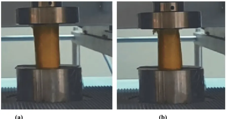
Transverse and axial compression tests were conducted on tubular woven preform reinforced composite pipes (TWP) (Figure 1-a) and filament wound composite pipes (FWP) (Figure 1-b) to understand the mechanisms of compressive failure and to examine the influence of reinforcement type on these mechanisms. Transverse compression tests were conducted according to ASTM Standard Test Method for Determination of External Loading Characteristics of Plastic Pipe by Parallel-Plate Loading (D-2412) and axial compression tests were conducted according to ASTM Standard Test Method for Compressive Properties of Rigid Plastics (D-695). The dimensions of the specimens were the same for both composite pipe types and showed in Figure 2.
Figure 1. Compression test specimens; a) tubular woven preform reinforced composite pipes (TWP), b) filament wound composite pipe (FWP)
Figure 2. Test specimen dimensions
During pretrial tests when compression was applied to the (empty) pipes, buckling occurred and the pipes were damaged more quickly than the internal walls. In order to eliminate buckling the compression tests were conducted both with fine sand filled pipes and empty pipes. The compression tests were performed with the help of a Shimadzu 100kN tester at a progressive speed of 1mm/ min. The load and displacement were recorded by standard coordinate (x-y) system. The specimens were tested at room temperature, which was about 20°C and the relative humidity was about 65%. The number of specimen of each set was three. The averages of values obtained from the test results were used to form force-displacement plot.
3. RESULTS AND DISCUSSION
The recent studies about the compressive behavior of tubular composites are mostly focused on their axial compression behaviors. However, a lateral compression test highlights the transverse behavior of the material, and even though this kind of tests is rather seldom, it is of high interest for the design of low-speed impact resistant structures [33]. The results of transverse compression tests (Figure 3) executed in this study showed that the maximum strength of the empty pipes reinforced by the tubular woven
preform method was about 800N, while the maximum strength of the empty pipes produced by the filament winding method was around 180N (Fig.3). These results proved that empty pipes produced with newly developed tubular woven preform can withstand forces with the prefactor 4.3 with compared to those of empty pipes produced with filament winding method.
Figure 3. Force – displacement diagram of empty pipes subjected
to transverse compression test
Moreover, the force-displacement curves for the compression test of the empty pipes in the axial direction are shown in Figure 4. The axial compressive strengths of both composite pipe types are ten times as much as their transverse compressive strengths. Also the amount of displacement in axial tests is far less than the ones observed in transverse tests. The empty pipes subjected to the axial compression tests show that the maximum strength of the pipes produced by the woven preform method is about 8000N, while the maximum strength of the pipes produced by the filament bending method is around 2800N. These results proves that empty pipes reinforced with novel tubular woven preform can withstand axial forces with the prefactor 2.8 when compared to those of empty pipes produced with filament winding method.
The damages seen in empty composite pipes during the transverse and axial compression tests are shown in Figure 5-6. From the images, it is clear that buckling occurs at empty pipes during the pressure tests. In order to prevent buckling during the compression tests, additional experiments were carried out with other pipe samples which were filled with sand.
The force-displacement curves of the sand-filled pipes which were subjected to the compression tests in the transverse direction are shown in Figure 7. As can be seen from the figure the damage propagation of sand filled pipes are quite slowly when compared to empty pipes and also the maximum strength of both pipes are much higher. The sand in the tubes increased the strength against lateral pressure so the experiment was terminated after the displacement exceeded 10 mm.
Figure 8 shows the force-displacement curves of the sand-filled pipes subjected to the compression tests in the axial direction. As can be seen from the figure, the maximum strength of the sand-filled pipes subjected to the axial compression test is around 6000N for the samples reinforced by the tubular woven preform while it is around 2300N for the samples produced by the filament winding method. The result proves that the sand filled TWP can withstand forces with the prefactor 2.48 when compared to
the sand filled FWP. This ratio is very close to the coefficient which was obtained in the compression test on empty pipes in axial direction. In filament wound composites, cracks easily propagate in the direction of the fibres. However, it is thought that the interlacement points of weft (90°) and warp yarns (0°) in tubular woven preforms are assumed to be a crack-stopping task. That is why the transverse and axial compression strengths of empty and sand filled TWP are higher than filament wound ones.
Figure 4. Force – displacement diagram of empty pipes subjected
to axial compression test
(a) (b) Figure 5. Transverse compression test of empty pipes; a) Before the test, b) After the test
(a) (b)
Figure 7. Force – displacement diagram of sand-filled pipes subjected to
transverse compression test.
Figure 8. Force – displacement diagram of sand-filled pipes subjected to
axial compression test
After the transverse tests, no visible damage to the naked eye was observed on the surface of the composite pipes while some apparent damages were occurred on the surfaces of pipes subjected to compression tests in the axial direction. Damages of the pipes after the axial compression tests are shown in Figure 9.
Figures 9a and 9c showed that buckling is formed on the internal walls of the pipes which were tested emptily while the tearing occurred suddenly in the pipes which were filled with sand as seen in Figures 9b and 9d with the red marked. 4. CONCLUSION
Composite pipes have numerous end uses like pressure vessels, pipe lines, oxygen and other gas cylinders, rocket motor casings, helicopter blade and storage tanks. Filament
winding is one of the most common methods to produce composite pipes. However, filament winding have some advantages for instance the filament fibre cannot be exactly oriented towards the lengthwise direction of the structure in respect of the winding process. Because of having no fibres in the thickness direction makes filament wound pipes weak to transverse impact loads and destructive environmental conditions. The aim of this study was to design and manufacture a tubular woven preform that can be used as textile reinforcement in composite pipes and compare transverse and axial compression behaviors of this pipe with filament wound one.
Empty and sand filled tubular woven preform reinforced composite pipes withstood transverse compression forces 4.3 and 1.8 times higher than filament wound ones respectively. In axial compression tests, tubular woven composites showed almost 2.8 times better performance than filament wound ones. In filament wound composites, cracks easily propagated in the direction of the fibres. However, the interlacement points of weft (90°) and warp yarns (0°) in tubular woven preforms had a crack-stopping task. That is why the transverse and axial compression strengths of empty and sand filled tubular woven preform reinforced composite pipes were higher than filament wound ones.
Figure 9. Failure of the specimens after axial compression tests; a) empty FWP specimen, b) sand filled FWP specimen, c) empty
TWP specimen, d) sand filled TWP specimen
REFERENCES 1. Hashmi MSJ, 2006. Aspects of tube and pipe manufacturing processes
meter to nanometer diameter., Journal of Materials Processing Technology 179, 5-10.
2. Zou GP, Taheri F. 2006. Stress analysis of adhesively bonded sandwich pipe joints subjected to torsional loading. International Journal of Solids and Structures 43, 5953-5968.
3. Shen H, Wen J, Yu D, Wen X, 2009. The vibrational properties of a periodic composite pipe in 3D space. Journal of Sound and Vibration 328, 57-70.
4. Mertiny P, Ellyin F, Hothan A, 2004. An experimental investigation on the effect of multi angle filament winding on the strength of tubular composite structures. Composites Science and Technology 64, 1-9.
5. Use of Composite Pipe Materials in the Transportation of Natural Gas (2002) Available at:
http://citeseerx.ist.psu.edu/viewdoc/download?doi=10.1.1.165.1163&r ep=rep1&type=pdf (accessed 12 march 2018).
6. Sari M, Karakuzu R, Deniz ME, Icten BM. 2011, Residual failure pressures and fatigue life of filament wound composite pipes subjected to lateral impact. Journal of Composite Materials 46(15), 1787-1794. 7. Xia M, Kemmochi K, Takayanagi H. 2002. Bending behavior of
filament-wound fiber-reinforced sandwich pipes. Composite Structures 56, 201-210.
8. Ma Y, Sugahara T, Yang Y, Hamada H. 2015. A study on the energy absorption properties of carbon/aramid fiber filament winding composite tube. Composite Structures 123, 301-311.
9. Xia M, Kemmochi K, Takayanagi H. 2001. Analysis of filament wound fiber reinforced sandwich pipe under combined internal pressure and thermomechanical loading. Composite Structures 51(3), 273-283.
10. Deniz ME, Karakuzu R. 2012. Seawater effect on impact behavior of glass epoxy composite pipes. Composites Part B 43(13), 1130-1138. 11. Onder A, Sayman O, Dogan T, Tarakcioglu N. 2009. Burst failure
load of composite pressure vessels. Composite Structures 89(1), 159-166.
12. Sayman O. 2005. Analysis of multi-layered composite cylinders under hygrothermal loading. Composites Part A, 36(7), 923-933.
13. Demir I, Sayman O, Dogan A, Arikan V, Arman Y. 2015., The effects of repeated transverse impact load on the burst pressure of composite pressure vessel. Composites Part B 68, 121-125.
14. Deniz ME, Ozdemir O, Ozen M, Karakuzu R. 2013. Failure pressure and impact response of glass epoxy pipes exposed to seawater. Composites Part B 53, 355-361.
15. Cohen D. 1997. Influence of filament winding parameters on composite vessel quality and strength. Composites Part A 28(12), 1035-1047.
16. Velosa JC, Nunesa JP, Antunesa PJ, Silva JF, Marques AT. 2009. Development of a new generation of filament wound composite pressure cylinders. Composites Science and Technology 69(9), 1348-1353.
17. Cohen D, Mantell S,, Zhao L. 2001. The effect of fiber volume fraction on filament wound composite pressure vessel strength. Composites Part B 32(5), 413-429.
18. Sung J, Chang P, Chun SH, Cheol GK, Kim U. 2002. Analysis of filament wound composite structures considering the change of winding angles through the thickness direction. Composite Structures 55(1), 63-71.
19. Jia X, Chen G, Yu Y, Li G, Zhu J, Luo X, Duan C, Yang X, Hui D. 2013. Effect of geometric factor, winding angle and pre-crack angle on quasi-static crushing behavior of filament wound CFRP cylinder. Composites Part B, 45, 1336-1343.
20. Peters ST. 2011. Filament winding-introduction and overview. In: Peters ST. (ed.). Composite Filament Winding. USA: ASM International
21. Ahmadi MS, Johari MS, Sadighi M, Esfandeh M. 2009. An experimental study on mechanical properties of GFRP braid pultruded composite rods. Polymer Letters 3(9), 560-568.
22. Harrocks AR, Anand SC. 2000. Handbook of Technical Textiles. New York: Woodhead Publishing Limited.
23. Pastore C. 2000. Opportunities and challenges for textile reinforced composites. Mechanics of Composite Materials 36(2), 97-116. 24. Yang B, Kozey V, Adanur S, Kumar S. 2000. Bending, compression,
and shear behavior of woven glass fiber epoxy composites. Composites Part B 31, 715-721.
25. Hosseinzadeh R, Shokrieh MM, Lessard L. 2006. Damage behavior of fiber reinforced composite plates subjected to drop weight impacts. Composites Science and Technology 66, 61-68.
26. Karakuzu R, Gulem T, Icten BM. 2006. Failure analysis of woven laminated glass–vinylester composites with pin-loaded hole. Composite Structures 72, 27-32.
27. Zhang J, Chaisombat K, He S, Wang CH. 2012. Hybrid composite laminates reinforced with glass/carbon woven fabrics for lightweight load bearing structures. Materials and Design 36, 75-80.
28. Baucom JN, Zikry MA. 2005. Low velocity impact damage progression in woven E-glass composite systems. Composites Part A 36, 658-664.
29. Icten BM, Karakuzu R. 2002. Progressive failure analysis of pin-loaded carbon–epoxy woven composite plates. Composites Science and Technology 62, 1259-1271.
30. Clark SR, Mouritz A., 2008. Tensile fatigue properties of a 3D orthogonal woven composite. Composites Part A 39, 1018-1024. 31. Reis PNB, Ferreira JAM, Santos P, Richardson MOW, Santos B.
2012. Impact response of Kevlar composites with filled epoxy matrix. Composite Structures 94, 3520-3528.
32. Ishikawa T, Chou T. 1982. Stiffness and strength behavior of woven fabric composites. Journal of Materials Science 17, 3211-3220. 33. Calme O, Bigaud D, Hamelin P. 2005. 3D braided composite rings
under lateral compression. Composites Science and Technology 65, 95-106.