115.6
ccurate Plane-Wave Excitation in
the
FDTD Methodi
LEVENT GUREL*, UGUR
OGuz,
ANDORHAN
ARIKAN
DEPARTMENT OF ELECTRICAL AND ELECTRONICS ENGINEERING
BILKENT UNIVERSITY
BILKENT, ANKARA, TURKEY
(lgurelk3ee. b i l k e n t . edu. tr)
1
Introduction
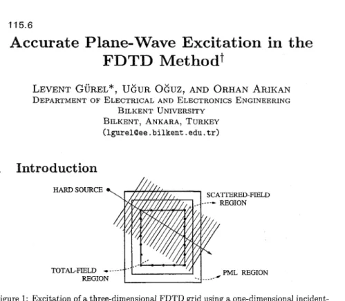
SCATTERED-FIELD HARD SOURCE --- REGION PML REGION TOTAL-FIELD ---Figure 1: Excitation of a three-dimensional FDTD grid using a one-dimensional incident- field array.
Several different techniques are developed to implement plane-wave excitation in the finite-difference time-domain (FDTD) [l-31 method, such as the initial-condition tech- nique [l], the hard-source technique [2], and the connecting-condition technique used in the total-field/scattered-field (TF/SF) formulation [2,4]. In the TF/SF formulation, the incident field has to be computed and “fed” to the three-dimensional (3D) FDTD grid on the boundary separating the total-field and the scattered-field regions. Since the incident field is a known quantity, a closed-form expression can be evaluated on every point of this boundary at each time step. However, a more efficient way of computing the incident field is to use an incident-field array (IFA), which is a one-dimensional (1D) FDTD grid set up to numerically propagate the incident field into the 3D FDTD grid as shown in Fig. 1. Then, the required incident-field values on the TF/SF boundary are interpolated from the values on the IFA [2].
Obtaining more accurate results has remained as a current issue since the FDTD method was introduced about three decades ago. Recently, significant progress has been reported in the development of more accurate absorbing boundary conditions (ABCs). tThis work was supported in part by NATO’s Scientific Affairs Division in the framework of the Science for Stability Programme and in part by the Scientific and Technical Research Council of Turkey (TUBITAK) under contract EEEAG-163.
0-7803-4178-3/97/$10 00 Q 1997 IEEE
[5] In this work, we address the accuracy issues another aspect of the FDTD method: plane-wave excitation.
2
Smoothing Windows
and
Filters
The discretization (sampling) of the source signal in the FDTD method may cause a sig- nificant aliasing error if the signal contains high-frequency components [6]. For instance, when a plane wave with an intended sinusoidal time dependence is abruptly turned on a t t = 0, the resulting time dependence of the plane wave becomes
e(t) = u(t) sin wot, (1)
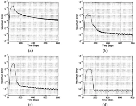
where u ( t ) is the unit step function and wo = 2 ~ / T o . The signal in Eq. (1) contains high frequency components and Figure 2(a) shows the maximum value of the error over both the total-field and scattered-field domains at each time step. It is seen that the maximum error in the computational domain decreases very slowly and does not reach a steady-state value after 800 time steps, which correspond to -10 periods for fo = 1 GHz. When the initial T0/2 portion of the signal in Eq. (1) is smoothened using a Hanning
10
'
10 5 10.' lii 5 10.' E $ 1 0 ' 10- Time Steps lo-' 1 0" 5 1 0 ' i2
lo4 Z 10-6 "-'o 2W 4W 6W 800 ~ i m e steps (a) (b) lo-' lo-' 10-2 10-2e
IO"e
lo" W W 5 lo" 5 io'' I" 3 105 to6 10-6 10.' IO-'B
0 2W 400 6W 800 0 200 400 600 800Time Steps Time steps
(c) ( 4
Figure 2: Plots of maximum error in the 3D FDTD grid as a function of time: (a) Sinu- soidal excitation starts abruptly. (b) Smoothened signal. (c) Anti-aliasing filter is used. (d) The signal is both smoothened and filtered.
window, the maximum error drops to a lower level as shown in Fig. 2(b). The use of an anti-aliasing filter on the signal in Eq. (1) and on its smoothened version results in even lover levels of the maximum error as shown in Figs. 2(c) and (d).
igher-Order Interpolation
The incident plane-wave values on the TF/SF boundary are interpolated from the discrete values on the 1D IFA as shown in Fig. 1. Regardless of the time-dependence of the incident plane wave, a higher-order interpolation technique should be expected to enhance the accuracy with which the plane wave is introduced to the 3D FDTD grid. Figures 3(a)- (d) show the maximum error for the cases of linear, quadratic, cubic and 5th-order interpolation. The error is observed to drop drastically as the order of the interpolation increases. 10 10 '
1
lo" I 10-5 1 o" io-' I- 0 2w 400 600 800 low Time steps(4
I . . , . . . , I-lO:l! I 0 2w 400 600 800 low Time steps(4
1 o-2 Time steps ( 4 '" 0 200 400 MM m 1wo Time StepsFigure 3: Plots of maximum error for various interpolation orders: (a) First order. (b) Second order. (c) Third-order. (d) Fifth order.
igh-rtesolution Incident-Field Array
Another way of reducing the excitation error is to use a finer gridding in the IFA to generate a more accurate plane wave. However, merely increasing the sampling frequency
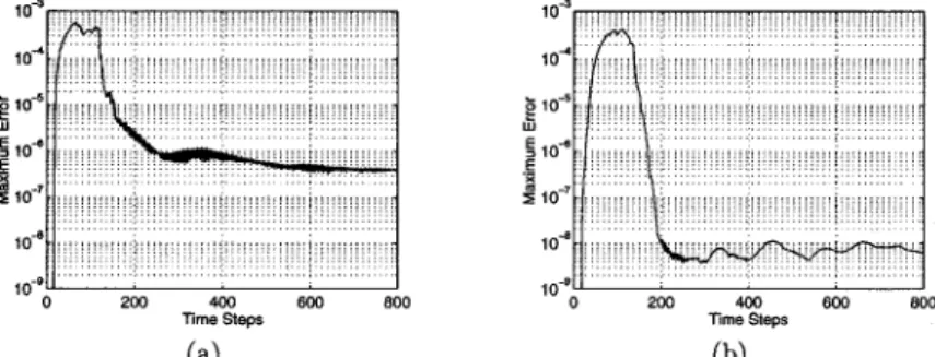
in the 1D IFA (by reducing the step sizes both in space and time in the 1D FDTD grid) has limited advantage. This is due to the fact that only some of the values on the 1D IFA are used in computing (interpolating) the values on the boundary of the 3D FDTD grid and this situation is equivalent to decimation of a sequence. Decimation operation should be carried out using a properly chosen decimation filter to avoid errors [7]. Figure 4(a) shows the maximum error when the input signal is smoothened as in Fig. 2(b) and the IFA is resolved 8 times better than the 3D FDTD grid. It is observed that the error is reduced, however, if a decimation filter is used, the error drops by another two orders of magnitude as shown in Fig. 4(b).
lo" 1 0"
e
1042
IO" w5
IO" 6 1 0" lo-sO 2W 400 6W 800 lime Steps 1 oJ 1 o4 g IO-' lz 4 1045
I" io-' 10" lo-'o 200 400 600 800 Time Steps ( 4 (b)Figure 4: Plots of maximum error when the IFA is resolved 8 times better than the 3D FDTD grid: (a) No decimation filter. (b) A decimation filter is used.
5
Conclusions
Several signal-engineering techniques are outlined that can be employed to enhance the accuracy of the plane-wave excitation in the FDTD method.
References
K. S. Yee, "Numerical solution of initial boundary value problems involving Maxwell's equations in isotropic media," IEEE %ns. Antennas Propagat., vol. AP-14, pp. 302-307, Apr. 1966.
A. Tafiove, Computational Electrodynamics: The Finite-Difference Time-Domain Method. Boston,
MA: Artech House, 1995.
K. S. Kunz and R. J. Luebbers, The Finite Difference Time Domain Method for Electromagnetics.
Boca Raton, FL: CRC Press, 1993.
G. Mur, "Absorbing boundary conditions for the finite-difference approximation of the time-domain electromagnetic-field equations," IEEE Trans. ~?ktTOmagn. Compat., vol. EMC-23, no. 4, pp. 377-
382, Nov. 1981.
J.P. Berenger. "A perfectly matched layer for the absorption of electromagnetic waves, J. Comput.
Phys., pp 185-200, Oct. 1994.
A. V. Oppenheim and R. W. Schafer, Discrete-Time Signal Processing. Englewood Cliffs, NJ:
Prentice Hall, 1989.
R. A. Gabel and R. A. Roberts, Signals and Linear Systems. New York: Wiley, 1973.