WELDING RESEARCH
Introduction
Recent technological advances have necessitated the development of new ma-terials as well as new methods for joining them. An example of such a material is the metal matrix composite (MMC), which is essentially a structure consisting of a com-bination of two or more macro compo-nents that dissolve within one another. Metal matrix composites, which both have a high elastic modulus of ceramic and high metal ductility, are used with conventional metallic materials in fields such as aircraft and aerospace engineering, as well as de-fense and automotive industries. Ratios such as strength/weight and strength/den-sity play an important role in metal matrix composites, and in so doing, they add something novel and innovative to the scope of structural materials (Refs. 1, 2).
As the demand for these new materials grows, studies related to the production and mechanical properties of composite materials have become a focus of
re-search. Additionally, many studies about the production processes and estimation properties for this kind of material are continuing. Furthermore, investigations on practical applications of secondary pro-cessing technologies (such as machining, joining, plastic forging, etc.) are also re-markable. Currently, research related to joining science and technology for the metal matrix composites (in particular, aluminum alloy matrix composites) also becomes one of the key-point issues for their potentially successful engineering applications.
There are still many problems with joining metal matrix composite materials (in particular, for the ceramic-reinforced aluminum alloy matrix composites) used
in fusion welding processes (Ref. 3). In the welding stage, existence of the difference between the chemical potential of the matrix and reinforcement material shows there is no thermodynamic balance between the two. Under the welding con-ditions, undesirable chemical reactions occur between the aluminum and SiC. The result is an inferior-quality welded joint.
Uncontrolled solidification is another problem that one may encounter in fusion welding. This process occurs in the weld-ing pool as cooled down; that is, the rein-forcement phases such as SiC particulates were strongly rejected by the solidification front and normal solidification processes of the welding pool were broken down that consequently led to microsegregation or inhomogeneous distribution of reinforce-ment material. As a result, there would be many micro and macro defects in the welded joint (Refs. 3, 4). As there are a number of problems that may occur in the process of fusion welding, the friction welding method (a solid form welding process) proves to be more effective.
Friction welding is a method that does not cause melting in the welded zone, and it works through applying friction-induced heat on the surfaces of materials. The fric-tion welding process is entirely mechani-cally powered, without any aid from elec-trical or other energy sources (Refs. 5, 6). In friction welding, the surfaces that cre-ate the friction during the welding process are maintained under axial pressure, known as the friction stage (Ref. 7). When the appropriate temperature is reached, the rotation movement is stopped, and the upset pressure is applied. The welding zone is thus subjected to a type of thermo-mechanical process that prevents grain structure deterioration (Refs. 8, 9). Fric-tion welding is a method that can be used in materials that have different thermal and mechanical properties.
Midling and Grong (1994) were
con-and AISI 1030 steel can be joined by friction welding
BY S. Ç̧ELIK AND D. GÜ̈NE
Ş
KEYWORDS
Friction Welding Weldability Testing Metal Matrix Composite Carbon SteelS. ÇELIK ([email protected]) and D. GÜNEŞ are with Balikesir University, Faculty of Engineering and Architecture, Dept. of Mechani-cal Eng., Cagis Campus, Balikesir, Turkey.
ABSTRACT
In conventional welding methods, such as those used in joining ceramic-reinforced aluminum matrix composites, a variety of problems occur. For instance, the element used for reinforcement, which increases the viscosity in the melting stage, makes the mixing of matrix and reinforcement material difficult, and this causes inferior joining quality and makes the establishment of welding difficult. Also, chemical reactions and undesirable phases are observed because there is a difference between the chemical potential of the matrix and reinforcement material. In this study, joining a SiC partic-ulate-reinforced A356 aluminum alloy and AISI 1030 steel by continuous drive friction welding was investigated. The integrity of the joints was also investigated by optical and scanning electron microscope (SEM), and the mechanical properties of the welded joints were assessed using microhardness and tensile tests. The results indicate that an aluminum matrix composite and AISI 1030 steel can be joined by friction welding.
.
WELDING RESEARCH
cerned with the development of an overallprocess model for the microstructure and strength evolution during continuous-drive friction welding of AI-Mg-Si alloys and AI-SiC metal matrix composites. In Part I, the different components of the model are outlined and analytical solu-tions presented, which provide quantita-tive information about the heat-affected zone (HAZ) temperature distribution for a wide range of operational conditions. In Part II, the heat and material flow models presented in Part I are utilized for the pre-diction of the HAZ subgrain structure and strength evolution following welding and subsequent natural aging. The models are validated by comparison with experimen-tal data and are illustrated by means of novel mechanism maps (Refs. 10, 11).
In their study, Pan et al. (1996) investi-gated the microstructure and mechanical properties of dissimilar friction joints be-tween aluminum-based MMC and AISI 304 stainless steel base materials. The terlayer formed at the dissimilar joint in-terface was comprised of a mixture of oxide (Fe(Al,Cr)2O4or FeO(Al,Cr)2O3) and FeAl3intermetallic phases. The notch
tensile strength of dissimilar MMC/AISI 304 stainless steel joints increased when the rotational speed increased from 500 to 1000 rev/min, and at higher rotation speeds there was no effect on notch tensile
strength properties (Ref. 12).
Zhou et al. (1997) examined the opti-mum joining parameters for the friction joining of aluminum-based, MMC materi-als. The notch tensile strengths of MMC/Alloy 6061 joints are significantly lower than MMC/MMC and Alloy 6061/Alloy 6061 joints for all joining pa-rameter settings. The fatigue strengths of MMC/MMC joints and Alloy 6061/6061 joints are also poorer than the as-received base materials (Ref. 13).
Uenishi et al. (2000) investigated spiral defect formation and the factors affecting
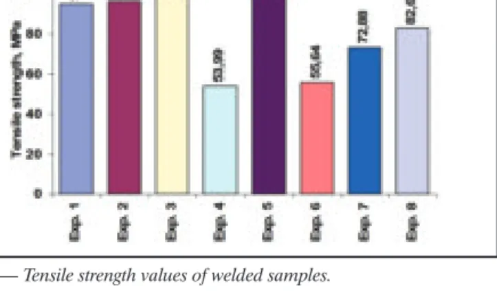
the mechanical properties of friction welded aluminum Alloy 6061 T6 and 6061/AI203composite base materials. Spi-ral defects are flow-induced defects formed when material and reinforcing Fig. 1 — Tensile strength values of welded samples. Fig. 2 — Hardness variations on horizontal distance.
Fig. 3 — Macro picture of the sample with friction welding.
Fig. 4 — Optical microstructures of weld zones with different parameters (50×). A — Experiment 2; B — experiment 3; C — experiment 4; D — experiment 5; E — experiment 6.
A
C
D
E
B
particles transfer to and are trapped in spi-ral arm regions located near the stationary boundary of friction welded joints. The tensile strengths of postweld heat treated MMC/MMC joints produced using a fric-tion pressure of 280 MPa were signifi-cantly stronger than as-received MMC base material (Ref. 14).
In their study, Lin et al. (2002) were able to successfully conduct friction welding be-tween two composite materials with the same matrix but a different reinforced ma-terial. Composite materials are SiC and Al2O3reinforced A7005 aluminum alloy. For composite materials, the following were used: size 6 and 15 μm, SiC particulate vol-ume percentage of 10%, and 15 μm Al2O3 ceramic particulate of the same volume per-centage. Consequently, the use of a SiC par-ticulate led to a concentration of reinforce-ment particulate in the HAZ. This results in an increase in hardening values in the plas-tic region, weakening welding strength, and narrowing HAZ (Ref. 15).
Lee et al. (2004) were able to achieve friction welding between a TiA1 alloy and AISI 4140 for a friction time of 30–50 s,
upset pressure varying in a range of 300–460 MPa, and upset time of 5 s at a rotating speed of 2000 rev/min. On the AISI 4140 side, they observed that the hardness values increased to the range of 600–900 HV, and no change in the TiA1 hardness value. How-ever, the tensile strength value was deter-mined to be as low as 120 MPa (Ref. 16).
Reddy et al. (2008) were able to success-fully weld AA6061 and AISI 304 austenitic stainless steel by means of the continuous rotating friction welding method. Direct welding of this combination resulted in brit-tle joints due to the formation of Fe2Al5. To alleviate this problem, welding was carried out by incorporating Cu, Ni, and Ag as a dif-fusion barrier interlayer. The interlayer was incorporated by electroplating. Welds with a Cu and Ni interlayer were also brittle due to the presence of CuAl2and NiAl3. Ag acted as an effective diffusion barrier for Fe avoiding the formation of Fe2Al5. There-fore, welds with an Ag interlayer were stronger and ductile (Ref. 17).
In the study by Fauzi et al. (2010), the ex-amination of the interface with ceramic/metal alloy friction welded
compo-nents is essential for understanding the quality of bonding between two dissimilar materials. Optical and electron microscopy as well as four-point bending strength and microhardness measurements were taken to evaluate the quality of bonding alumina and 6061 aluminum alloy joints produced by friction welding (Ref. 18).
In this study, the joining capability of SiCp-reinforced A356 aluminum matrix
composite and AISI 1030 steel was stud-ied by continuous-drive friction welding. Therefore, after welding of samples, ten-sile and hardness experiments were car-ried out. For metallographic investiga-tions, optical microscope and SEM have been used. Energy-dispersive spec-troscopy (EDS) analysis was carried out for chemical composition investigations on welding and HAZs.
Experimental Procedure
In this study, SiCp-reinforced A356 aluminum matrix composite and AISI 1030 steel were used. A SiC particulate-re-inforced A316 aluminum matrix compos-ite was prepared using the vortex method. In the Al/SiC composite material, some reactions take place between the matrix and reinforcement material during cast-ing. The Al4C3, which formed as a result of these reactions, renders the welding very brittle. Very high heat input makes Al4C3even more pronounced. The com-pound takes form at a temperature be-tween 700° and 1400°C (Refs. 1, 19). To prevent brittleness of the composite mate-rial caused by the Al4C3compound, the
vortex method that does not require very high heat input is used. The casting was carried out using the stir casting method at 700°C.
The chemical composition of the A356 aluminum alloy is presented in Table 1. It should be noted that the SiC particulate
WELDING RESEARCH
Table 1 — Chemical Composition of the A356 Material (wt-%)
Al Fe Si Ti Mn Zn Cu Mg Ni Cr
92.28 0.12 7 0.2 0.03 0.02 0.02 0.28 0 0
Table 2 — Chemical Composition of the AISI 1030 Steel (wt-%)
C Ni Cr Si Mn P Cu Mo Nb Fe
0.297 0.100 0.082 0.143 0.636 0.011 0.167 0.011 <0.002 98.511
Table 3 — Mechanical Properties of the Base Materials
Materials Yield Strength Tensile Strength Elongation Hardness
(MPa) (MPa) (%) (HV50)
AISI 1030 477.68 725.46 5.20 232.3
6% Al/SiCp 103.76 149.57 0.025 64.5
Fig. 5 — Optical microstructures of the weld zone and HAZ of the experiment 3 (200×). A — HAZ (side of MMC); B — weld zone; C — HAZ (side of AISI 1030).
volume percentage of 6% in 44 μm di-mensions were used in the study. Looking to the related literature (Ref. 20) and the results of a number of preliminary cast-ings, it was assumed that 6% SiC would be the appropriate particulate ratio to use. The chemical composition of AISI 1030 steel is shown in Table 2. Mechanical prop-erties of this steel are presented in Table 3. The samples were processed at ∅20 ×80 mm dimensions for friction welding.
The study was conducted using a con-tinuous-drive friction welding machine at 3000 rev/min at the Engineering and Ar-chitecture Faculty of Balikesir University. Surfaces of the joining parts were ground, cleaned, and then fixed to the machine. The welding parameters, which were de-termined after consulting the relevant lit-erature (Refs. 15, 20, 21) and preliminary experiments, are shown in Table 4.
Tensile properties of the welded sam-ples were prepared according to the EN 895 standard by leaving the welding zone in the center. When running tensile tests, 4-mm/min tensile rates were used. Hard-ness tests were carried out in the
cross-sec-tion interface of the Al/SiC composite and AISI 1030 steel friction welded joints. The microhardness values were measured on both sides of the welded specimens with the Vickers method using a 50-g load.
The microstructural features of the friction welded joints are investigated by using optical and scanning electron micro-scopes. The samples were ground by using SiC sandpapers and polished with a
0.3-μm Al2O3powder, then AISI 1030 and MMC sides were etched by using different solutions. The AISI 1030 was etched for 4 s by using 4% nital, while the %6 Al/SiCp
material was etched for 2 min using a Keller reagent (2.5 mL HNO3, 1.5 mL HCI, 1 mL HF, and 95 mL distilled water).
Results and Discussion
Tensile Test Results
Friction welding experiments were con-ducted using the aforementioned welding parameters. In the tensile test samples, fractures occurred on the side of the MMC material in the HAZ. The occurrence of fractures in the MMC zone was apparently
WELDING RESEARCH
Table 4 — The Process Parameters Used in the Friction Welding Experiments
Experiment Friction Pressure Friction Time Upset Pressure Upset Time No. (Pf) (MPa) (tf) (s) (Pu) (MPa) (tu) (s)
Experiment 1 40 4 40 4 Experiment 2 40 6 40 4 Experiment 3 40 10 40 4 Experiment 4 20 6 40 4 Experiment 5 20 12 40 4 Experiment 6 20 4 60 4 Experiment 7 20 6 60 4 Experiment 8 20 8 60 4
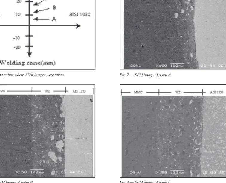
Fig. 6 — The points where SEM images were taken. Fig. 7 — SEM image of point A.
caused by a deficiency of connection, which is a reduced microjoining interface be-tween SiCpand A356 aluminum. On the
other hand, the reason that a fracture took place in the welding zone could be attrib-uted to the presence of intermetallic phases such as Fe2Al5and FeAl3, which resulted from the diffusion of materials. This was caused by mechanical locking of the MMC and AISI 1030 materials, but it could also be the impact of SiCp, which prevented
dif-fusion of the materials, the fact that Al and Fe promote the intermetallic phases (Refs. 12, 17, 22, 23).
The tensile test results of the friction-welded joints are given in Fig. 1 in a bar chart format. According to the results of the tensile tests, the tensile strength of the sample from experiment 3 (99.05 MPa) is 33.7% less than the tensile strength of MMC (1349.57 MPa), while the tensile strength of the sample used in experiment 4 (53.99 MPa) is 63.9% less than the sile strength of MMC. In general, the ten-sile strength of materials used in friction welding must be close to that of the mate-rial with the lowest tensile strength. In the tests, the tensile strength of the welded zone was determined even lower than that of MMC material, which has the lowest strength. This can be explained that the lack of strong interface connection strength between the reinforcement mate-rial and matrix matemate-rial, and acting of SiCp as a gap in the welding zone reduces the welding strength.
It can be concluded that the friction welding parameters are effective on joint strength. With a long friction time, zones of diffusion containing brittle intermetallic components were formed. A connection could not be established with a short period of friction time and low friction rate with upset pressure. To obtain high strength, the friction time must be as short as possible, while friction and upset pressure levels re-main high. In short periods of friction time, a very small diffusion area forms, and this
zone is removed from the joining interface by means of pressure during the welding process in which upset pressure is exerted. The results matched the data in pre-viously conducted studies (Refs. 21, 23). Microhardness Test Results
When looking at the hardness graph in Fig. 2, it is clear that hardness values change when moving away from the welding zone and toward the main materials. This change continues until the hardness values of the main materials are reached. On the MMC side, where particle fracture occurred, the increase in hardness values begins as a more particulate concentrate in the unit area, and it reaches its maximum level on the steel side of the weld zone. Five of the test sam-ples with high tensile strength were exam-ined for microhardness, and the results are provided in Fig. 2.
In experiments 2, 3, and 5, high pres-sure and a long period of friction led to an increase in intermetallic phases with re-sulting deformation. This created an ex-pansion of the weld zone. It is observed that deformation hardening, intermetallic phases originating from iron, aluminum, and fracturing of SiC increased the hard-ness in the region that deformed and near to the weld zone (Ref. 24). It is possible that there were particle transitions in the viscose structure of these samples due to the upset and heat. It should also be noted that a part of Fe passes to the side of MMC during welding, while Al and Si pass to the side of AISI 1030 and accumulate in the weld zone, causing an increase in hard-ness. These transitions were determined by an EDS analysis, which is explained in a subsequent section. Due to the fact that the friction time of test samples was less than 10 s, the occurrence of higher hard-ness values, which could cause weaker welding strength, was prevented.
In experiments 4 and 6, it was ob-served that the friction and upset pres-sures were low while the weld zone be-tween MMC and AISI 1030 materials was narrower than it ought to be. Because of this, diffusion between the materials
could not be achieved. This was due to the fact that the friction pressure and time were not sufficient for the materials to diffuse, and the joint between the two materials was very slight. The highest hardness values of the weld zone were measured at the sample of experiment 3, while the sample from experiment 4 showed the lowest microhardness values. It was observed that friction time and pressure values have a direct effect on microhardness values.
Macro- and Microstructure Results The structural changes taking place when welding two different materials can be classified into three different areas. The first of these shows the partially deformed section of MMC, while the second shows the fully deformed section in the weld cen-ter, and the third shows the partially de-formed zone of AISI 1030 — Fig. 3.
In examining the microstructure, it was observed that there were changes in the particle structure of the MMC material, whereas not much change took place in the AISI 1030 material. The reason no change occurred on the AISI 1030 side was the low friction pressure and time.
In general, due to the effects of friction and upset pressure, fracture in the SiC par-ticulate was observed in the MMC material when approaching the weld zone. This phe-nomenon led to deposits of SiC in the weld zone. Uenishi et al. (Ref. 14) reported that reinforcing Al2O3particles in the MMC base material are fractured in the zone close to the weld interface. After samples were examined under an optical microscope, it became easier to explain why the hardness values in the weld zone increased at higher pressure and time. Moreover, the occur-rence of Al-Fe intermetallic phases is ex-pected as a result of heat generated by the friction as well as upset pressure. In the lit-erature (Refs. 12, 17, 22, 23), it has been claimed that intermetallic phases between Al and Fe such as Fe2Al5and FeAl3can take
place after the diffusion of the materials under high pressure if a sufficient amount of heat (at higher than 400°C) is provided. The subject material’s intermetallic phases adversely affect the weld strength because they form a brittle structure. To prevent this,
WELDING RESEARCH
there must be high friction and upset pres-sure, as well as sufficient friction time men-tioned before.
Figure 4 depicts the microstructure im-ages of samples in five different experi-mental conditions. In examining samples 4 and 6, it can be observed that the welding is like a line, and the zone of transition where the materials diffuse into each other is not revealed. In visual and micro-scopic examinations of the samples, it was observed that flange and weld zones were not formed. It was also observed that the materials were connected only by means of mechanical locking, and there was no diffusion between the materials due to the fact that the necessary friction tempera-ture could not be achieved with the insuf-ficient friction pressure and time.
The joining quality of the samples from experiments 2, 3, and 5 was very good, es-pecially as the width of the weld zone can easily be seen. It can further be seen from MMC that the materials are sufficiently dif-fused to ensure joining. The diffusion be-tween the materials as well as the formation of the weld zone was adequately achieved due to the high pressure and sufficient fric-tion. Detailed microstructural images be-long to the zones 1, 2, and 3 depicted in Fig. 3 are shown respectively in Fig. 5A–C.
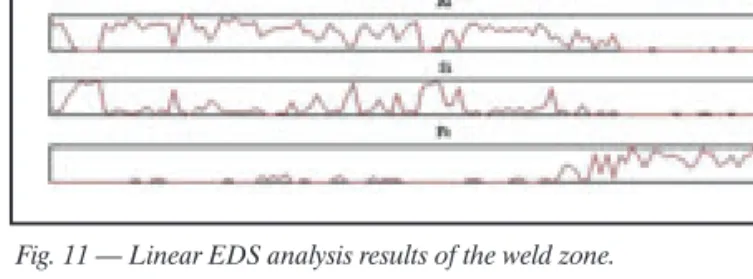
In the friction welding process, circular velocity is zero at the center. As the diam-eter and distance from the center in-creases, this velocity increases. In connec-tion with this, fricconnec-tion and temperature rise. Moreover, the width of the HAZ gets larger (Refs. 24–26). These changes were investigated throughout the welded area at various recorded distances from the welding center. Deeply assessed points of A, B, and C in the welded joint are de-picted in Fig. 6, and SEM images of these points taken from the welded joint zone are shown in Figs. 7–9. Following the SEM investigation, a linear EDS analysis of zone C was carried out. In Fig. 10, the lines and points used in the EDS analysis are re-vealed, and Fig. 11 depicts the results. In
Table 5, values ob-tained from point analysis can be seen.
Examining the SEM images and EDS re-sults, the distribution of Al, SiCp, and Fe can
be seen in the weld zone. In the weld zone, it can be observed that the Fe element is more diffused on the side of the MMC while Al and SiCpwere not very diffused on the AISI 1030 side. On the side of MMC, as the weld zone is approached, the size of the SiC particulate became smaller; in other words, they were broken. As was previously explained, microhardness val-ues in the weld zone increase as the amount of particulate in each unit zone in-creases, which in itself is caused by the fracture of SiC particulate that accumu-lated in the weld zone. In the SEM images, SiCpclustering in the weld zone was not observed. This supports the results that the weld strength in this sample is high.
When examining the fracture surfaces more closely, we can see smooth and bright surfaces that mean it is a brittle frac-ture. In Fig. 12, it can be observed that there were many indentations on the sur-face in the form of white braids that re-sulted from the tensile force that was ap-plied. Also, there were large dents with ductile fractures prevalent in these sec-tions of the material.
To be able to understand the Fe, SiCp, and Al status on the fracture surface, a lin-ear EDS analysis was taken on the AISI 1030 — Fig. 12. The results of the linear analysis are shown in Fig. 13. The fact that SiC, Al, and Fe materials are on the same surface and also that there are remains of MMC material on the fracture surface
indi-cate the fracture took place on the MMC side close to the welding zone.
Conclusions
1. In the tensile tests applied to the welded samples, it was observed that exper-iment 3 had the highest tensile strength (99.05 MPa), whereas experiment 4 had the lowest tensile strength (53.99 MPa). It was observed that friction pressure and friction time were important for welding strength. Friction pressure has to be at the optimum value where it does not cause high defor-mation but still allows for diffusion.
2. In the examinations of hardness per-formed on the welded samples, hardness values are not linear, also they increase while moving away from the welded zone toward the main materials. The increase in hardness values in the welded zone is the result of intermetallic phases such as Fe2Al5and FeAl3, internal stress
generat-ing by high temperature differences, de-formation hardening, and fracturing of SiCpbecause of high pressure in the zone. 3. In the microstructural examinations performed on the weld zone, three sepa-rate zones were encountered: the HAZ side to the MMC; the weld zone (de-formed after being exposed to high tem-perature values); and the HAZ side to AISI 1030. Substantial structural change was not observed in the HAZ side to AISI 1030. This is due to the fact that the tem-perature did not reach sufficient values for the deformation of AISI 1030 during fric-tion welding.
4. In investigating the SEM images, the diffusion of SiCp, Al, and Fe were ob-served in the weld zone. It was also noted that as SiC was located closer to the weld
WELDING RESEARCH
Fig. 12 — SEM image of fracture surface on the side of AISI 1030 material and EDS analysis line.
Fig. 13 — Linear EDS analysis results of fracture surface on the side of AISI 1030 material.
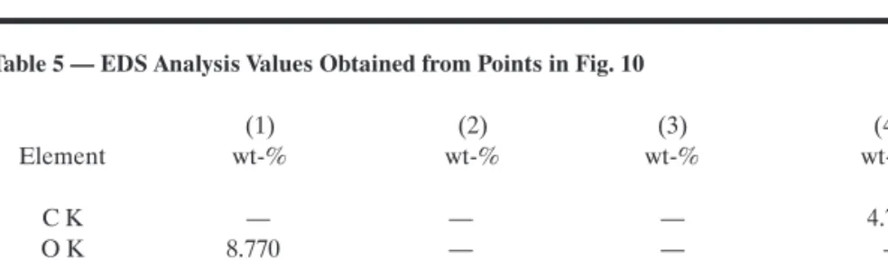
Table 5 — EDS Analysis Values Obtained from Points in Fig. 10
(1) (2) (3) (4) Element wt-% wt-% wt-% wt-% C K — — — 4.763 O K 8.770 — — — Al K 56.328 78.551 — — Si K 34.902 5.702 — 0.193 Fe K — 15.747 100.000 94.326
WELDING RESEARCH
time by working below melting tempera-tures. More specifically, it has shown that SiC-reinforced A356 aluminum alloy can be successfully joined to AISI 1030 steel by friction welding.
References
1. Zhu, Z. A. 1988. Literature survey on fab-rication methods of cast reinforced metal com-posites. Edited by S. G. Fishman and A. K. Dhingra. ASM/TMS Committee, World Mate-rials Congress, Sept. 24–30, Chicago, Ill.
2. Han, N. L., Yang, J. M., and Wang, Z. G. 2000. Role of real matrix strain low cycle fatigue life of a SiC particulate reinforced aluminum composite. Scripta Mater. 43: 801–5.
3. Zhang, X. P., Quan, G. F., and Wei, W. 1999. Preliminary investigation on joining per-formance of SiC-reinforced aluminum metal matrix composite by vacuum brazing. Compos-ites Part A 30: 823–7.
4. Zhang, X. P., Ye, L., Mai, Y. W., Quan, G. F., and Wei, W. 1999. Investigation on diffusion bonding characteristics of SiC particulate rein-forced aluminum MMC. Composites Part A 30: 1415–21.
5. Meshram, S. D., Mohandas, T., Mad-husudhan, and Reddy, G. 2008. Friction weld-ing of dissimilar pure metals. J. Mater. Process
10. Midling, O. T., and Grong, O. 1994. A process model for friction welding of A1-Mg-Si alloys and Al-SiC metal matrix composites — I. HAZ temperature and strain rate distribution. Acta Metall. Mater. 42(5): 1595–1609.
11. Midling, O. T., and Grong, O. 1994. A process model for friction welding of A1-Mg-Si alloys and Al-SiC metal matrix composites — I. HAZ microstructure and strength evolution. Acta Metall. Mater. 42(5): 1611–22.
12. Pan, C., Hu, L., Li., Z., and North, T. H. 1996. Microstructural features of dissimilar MMC/AISI 304 stainless steel friction joints. J. Mater. Sci. 32: 3667–74.
13. Zhou, Y., Zhang, J., North, T., and Wang, H. Z. 1997. The mechanical properties of friction welded aluminum-based metal-matrix composite materials. J. Mater. Sci. 32: 3883–89. 14. Uenishi, K., Zhai, Y., North, T. H., and Bendzsak, G. J. 2000. Spiral defect formation in friction welded aluminum. Welding Journal 79(7): 184-s to 93-s.
15. Lin, C. B., Chou, C., and Ma, C. L. 2002. Manufacturing and friction welding properties of particulate reinforced 7005 Al. J. Mater. Sci. 37: 4645–52.
16. Lee, W. B., Kim, M. G., Koo, J. M., Kim, K. K., Quesnel, D. J., Kim, Y. J., and Jung, S. B. 2004. Friction welding of TiAl and AISI 4140.
J. Mater. Sci. 39: 1125–8.
17. Reddy, M. G., Rao, S. A., and
Mohan-20. Lin, C. B., Mu, C. K., Wu, W. W., and Hung, C. H. 1999. The effect of joint design and volume fraction on friction welding properties of A360/SiC(p) composites. Welding Journal 78(3): 100–8.
21. Lienert, T. J., Baeslack, W. A., Ring-nalda, J., and Fraser, H. L. 1996. Inertia-friction welding of SiC-reinforced 8009 aluminum. J. Mater. Sci. 31: 2149–57.
22. Peyre, P., Sierra, G., Deschaux-Beaume, F., Stuart, D., and Fras, G. 2007. Generation of aluminum-steel joints with laser-induced reac-tive wetting. Mater. Sci. and Eng. A 444: 327–38. 23. Naoi, D., and Kajihara, M. 2007. Growth behavior of Fe2Al5during reactive diffusion be-tween Fe and Al at solid-state temperatures. Materials Sci. and Eng. A 459: 375–382.
24. Li, Z., Maldonado, C., North, T. H., and Altshuller, B. 1997. Mechanical and metallurgi-cal properties of MMC friction welds. Welding Journal 76(9): 367–73.
25. Noh, M. Z., Hussain, L. B., and Ahmad, Z. A. 2008. Alumina-mild steel friction welded at lower rotational speed. J. Mater. Process Tech. 204: 279–83.
26. Çelik, S., and Ersözlü, I. 2009. Investi-gation of the mechanical properties and mi-crostructure of friction welded joints between AISI 4140 and AISI 1050 steels. Materials and Design 30: 970–6.
CAN WE TALK?
The Welding Journal staff encourages an exchange of ideas with you, our readers. If you’d like to ask a question, share an idea or voice an opin-ion, you can call, write, e-mail or fax. Staff e-mail addresses are listed below, along with a guide to help you interact with the right person.
Publisher
Andrew Cullison [email protected], ext. 249 Article Submissions Editor
Mary Ruth Johnsen [email protected], ext. 238 Feature Articles
Associate Editor Howard Woodward [email protected],ext. 244 Society News, Personnel Associate Editor
Kristin Campbell
[email protected], ext. 257 New Products
News of the Industry
Managing Editor Zaida Chavez [email protected], ext. 265 Design and Production Sr. Production Coordinator
Brenda Flores
[email protected], ext. 330 Production
Advertising Sales Director Rob Saltzstein [email protected], ext. 243 Advertising Sales Advertising Sales & Promotion Coordinator
Lea Paneca
[email protected], ext. 220 Production and Promotion
Sr. Advertising Production Manager Frank Wilson
[email protected], ext. 465 Advertising Production
Peer Review Coordinator Melissa Gomez
[email protected], ext. 475 Peer Review of Research Papers
Welding Journal Dept. 550 NW LeJeune Rd. Miami, FL 33126 (305/800) 443-9353 FAX (305) 443-7404