cavity prototype has been designed and is now under construction for the RF characterization.
REFERENCES
1. J.W. Wang and G.A. Loew, Field-emission and RF breakdown in high-gradient room-tempera linac structures, In proceedings of the joint US-CERN-Japan school, RF engineering for accelerators, IOP, SLAC-PUB-7684, 1997.
2. W.D. Kilpatrick, Rev Sci Instrum 28 (1957), 824.
3. H. Braun et al., Frequency and temperature dependence of electrical breakdown at 21, 30, and 39 GHz, Phys Rev Lett 90 (2003), 22. 4. Shapiro et al., Theoretical analysis of overmoded dielectric photonic
band gap structures for accelerator applications, In proceedings of the particle accelerator conference, 2003 p. 1255.
5. M. Hill, High-gradient millimetre wave accelerator on a planar dielec-tric substrate, Phys Rev Lett 87 (2001), 94801.
6. J. Yablonovitch, Photonic band-gap structures, J Opt Soc Am B 10 (1993), 283.
7. J.D. Joannoupolous, R.D. Meade, and J.N. Winn, Photonic crystals: Molding the flow of light, Princeton University Press, Princeton, NJ, 1995.
8. A. Andreone et al., A study on a mono-modal accelerating cavity based on photonic band-gap concepts, In workshop on physics with a multi-MW proton source, CERN, Geneva, 2004.
9. A. Andreone et al., Approaching to a mono-modal accelerating cavity based on photonic band-gap concepts, In proceedings of the European particle accelerator conference, 2004, p. 1309.
© 2006 Wiley Periodicals, Inc.
PLASMONIC STRUCTURES WITH
EXTRAORDINARY TRANSMISSION AND
HIGHLY DIRECTIONAL BEAMING
PROPERTIES
Humeyra Caglayan,1,2Irfan Bulu,1,2and Ekmel Ozbay1,2,3
1Nanotechnology Research Center
Bilkent University Bilkent Ankara 06800, Turkey 2Department of Physics Bilkent University Bilkent Ankara 06800, Turkey
3Department of Electrical and Electronics Engineering
Bilkent University Bilkent
Ankara 06800, Turkey
Received 24 May 2006
ABSTRACT: We studied the grating– coupling phenomena between
surface plasmons and electromagnetic waves in the microwave spec-trum. We first present the experimental and theoretical results of an en-hanced microwave transmission though a subwavelength circular annu-lar aperture with and without metallic gratings. We demonstrate that a 145-fold enhancement factor could be obtained with a subwavelength circular annular aperture that was surrounded by periodic metallic gratings. This was assisted by the guided mode of the coaxial waveguide and by coupling to the surface plasmons. We present the angular trans-mission distributions from circular annular apertures, and circular an-nular apertures surrounded by concentric periodic grooves. At the sur-face mode resonance frequency, the transmitted electromagnetic waves from the subwavelength circular annular aperture surrounded by con-centric periodic grooves have a strong angular confinement with an an-gular divergence of⫾3°. We demonstrate that only the output surface is responsible for the beaming effect. Furthermore, we present the field
distributions and showed that there is no beaming effect at the off-reso-nance frequency. © 2006 Wiley Periodicals, Inc. Microwave Opt
Technol Lett 48: 2491–2496, 2006; Published online in Wiley Inter-Science (www.interscience.wiley.com). DOI 10.1002/mop.22015 Key words: subwavelength aperture; enhanced transmission; surface
plasmon; beaming; annular aperture; grating
1. INTRODUCTION
The transmission of electromagnetic (EM) waves through a single subwavelength aperture has been studied for many years. As defined in the standard diffraction theory by Bethe [1] in 1944, a circular aperture with a subwavelength diameter transmits EM waves rather poorly⬃(d/),4in which exiting EM waves are fully
diffracted in all directions. These two disadvantages of low trans-mission and diffraction are the main problems in controlling of light, especially for subwavelength scales.
The light waves that occur with the collective oscillations of the electrons at the surface of a conductor in the longitudinal direction are known as surface plasmons (SPs). SP modes have longer wave vectors than light waves of the same energy; hence electromag-netic radiation does not interact with the SP modes of a smooth metal surface [2]. Therefore, they are called non-radiative surface plasmons, which describe in turn the fluctuations of the surface electron density. Their electromagnetic fields decay exponentially into the space, perpendicular to the surface and have their maxi-mum in the surface, as is characteristic for surface waves. In order to couple the incident light to SP there are some techniques such as the ATR coupler and grating coupler. In the grating coupler method, the gratings on the surface can provide impinging free waves with additional momentum arising from the grating periodic structure, in which the linear free wave dispersion relation changes into a set of straight lines that can then match the SP dispersion relation [2].
It has been shown that when the metal surface surrounding the subwavelength hole is corrugated, the incident light can couple to SPs. A resonant interaction leads to an enhanced transmission at wavelengths determined by the corrugation period [3– 8]. It is also possible to confine the transmitted beam with the use of the periodically corrugated metal surface with subwavelength aper-tures [9 –12]. This feature of SPs provides the ability to solve the two main problems in the controlling of light while using the structures with subwavelength components by the enhancement of light and the guiding of light.
In 1992, optical near-field microscope researchers have pro-posed the use of coaxial aperture to achieve an enhanced trans-mission [13]. Soon after, Baida et al. proposed a similar idea, stating that it was possible to optimize the transmission enhance-ment and angular confineenhance-ment using a subwavelength circular coaxial aperture with a surrounding array of grooves [14, 15].
In this article, we investigated the beaming properties of the subwavelength circular apertures with grating. We will present the beaming of electromagnetic waves through one sided grating structures as well as the beaming of electromagnetic waves in the resonance and off-resonance frequencies. In our previous papers, we presented the enhancement of transmission and beaming of the transmitted light through subwavelength circular aperture and cir-cular annular aperture surrounded with and without concentric periodic grooves. In this work we will also present that it is possible to scale such structures and obtain these properties in different frequency regimes.
2. EXPERIMENT AND RESULTS
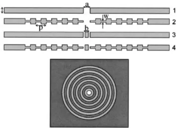
We performed our experiments between 10 and 18 GHz corre-sponding to a wavelength region of 16.7–30 mm and used four different metallic (aluminum) structures. All the structures have a subwavelength hole in the center with a diameter of (a) 8 mm. The gratingless sample (Sample 1) with a thickness of (t) 8 mm was used as a reference sample. The second sample had an identical aperture surrounded by six rectangular grooves. The periodicity of the grooves is 16 mm and the thickness of the grooved metal (w) is 3.2 mm. The schematic description of our structures is shown in Figure 1. The experimental setup for the transmission measure-ments consisted of an HP 8510C network analyzer and two stan-dard gain horn antennas to measure the transmission amplitude. Transmission is the intensity of the field transmitted to the other side of the structure with respect to free space. Radiation was normally incident upon the sample from 15 cm by source antenna. The receiver antenna was 10 cm away from the sample (Fig. 2). We used a CST microwave studio in our calculations. CST mi-crowave studio uses the finite integration technique in time domain calculations [16].
The transmission results for Sample 1 and 2 are shown in Figure 3. The experimental results are in good agreement with the FDTD calculations. For Sample 2, a transmission peak was mea-sured between 12.9 and 14 GHz with transmission amplitude of 0.025. However, the Sample 1 transmission was under 0.0025. Twentyfold enhancement was obtained at the resonance frequency with Sample 2. This resonance is attributed to the surface plasmon resonance, excited with the help of the periodic gratings on the surface.
For a further increase in transmission, we designed an an-nular aperture that can support a TE mode around 13 GHz. This structure (Sample 3) is identical to Sample 1 with a rod inside the hole. The diameter of the rod is 6.6 mm and the length of the rod is 8 mm. Figure 4 shows that the transmission at the TE
Figure 4 Calculated (dashed line) and measured (dotted line) transmis-sion results for Sample 3 and the straight line is the transmistransmis-sion result for Sample 2. The transmission from Sample 3 is higher than Sample 2 at the resonant frequency. [Color figure can be viewed in the online issue, which is available at www.interscience.wiley.com]
Figure 1 Schematics of the four metallic samples and top view of Sample 2
Figure 2 The experimental setup for transmission measurements. The experimental setup for the transmission measurements consisted of an HP 8510C network analyzer and two standard gain horn antennas to measure the transmission amplitude. Radiation was normally incident upon the sample from 15 cm by source antenna. The receiver antenna was 10 cm away from the sample. [Color figure can be viewed in the online issue, which is available at www.interscience.wiley.com]
Figure 3 Transmission spectrum of Sample 1 and 2. The dotted lines indicate theoretical calculations and the straight lines indicate measure-ments. The higher transmission lines are for Sample 2. [Color figure can be viewed in the online issue, which is available at www.interscience.wiley. com]
mode frequency from Sample 3 is higher than the transmission from Sample 2 at the SP resonance frequency. Hence, we combined Sample 2 and 3 to obtain an even higher transmis-sion. The combination of the annular aperture and grooved structure (Sample 4) showed extraordinary high transmission at 12.9 GHz (23.25 mm) via the coupling to the surface waves and the guided mode of annular aperture (Fig. 5). Including the reduction in the area of the aperture, a 450-fold enhancement was achieved through the subwavelength annular aperture [8]. These results show that using a circular annular aperture sur-rounded with periodic grooves can in turn achieve an extraor-dinary transmission from a subwavelength aperture.
It is also possible to scale these structures to 100 GHz and observe the same effects. We designed the structures by scaling the dimensions of our samples. As expected, we observed a transmis-sion peak for Sample 2 due to SP resonance (Fig. 6) around 105
GHz. Furthermore, we calculated transmission from Samples 3 and 4. Figure 7 shows that Sample 4 has the highest transmission due to the combination of two effects. The enhancement of Sample 4 at the resonance frequency with respect to the Sample 1 is 180. These properties can be used to construct miniaturized optoelec-tronic circuits with subwavelength components even at small scales.
In order to investigate the second problem (diffraction) of manipulating light, we measured the angular distributions of our four samples using another experimental setup. This setup is very similar to the transmission setup. The receiver antenna was placed 50 (22) cm away from the samples back face and was connected to a rotating arm to measure the angular dependence of the radi-ation in our angular distribution setup (Fig. 8). We changed the angle of the receiver antenna with the help of a rotating arm with a 1° resolution.
We measured the angular distributions for our four samples. Figure 9 shows the normalized, measured, and calculated angular transmission distribution at the resonance frequency for Samples 1 and 2. The angular divergence of the beam transmitted through Sample 1 is⫾12°, where the beam that emerges from Sample 2 is ⫾3°. Although, in both samples electromagnetic waves
transmit-Figure 6 Transmission spectrum of Sample 1 and 2 structures that works around 100 GHz. Sample 2 has higher transmission than Sample 1 as expected. [Color figure can be viewed in the online issue, which is available at www.interscience.wiley.com]
Figure 7 Transmission spectrum of Sample 3 and 4 structures that works around 100 GHz. Sample 4 has the highest transmission. [Color figure can be viewed in the online issue, which is available at www.interscience. wiley.com]
Figure 8 The experimental setup used in angular distribution measure-ments. This setup is very similar to the transmission setup. The receiver antenna was placed 50 (22) cm away from the samples back face and was connected to a rotating arm. [Color figure can be viewed in the online issue, which is available at www.interscience.wiley.com]
Figure 5 The comparison of the transmissions from Sample 2, 3, and 4. Sample 4 has the higher transmission due to the coupling of TE mode and SP mode. [Color figure can be viewed in the online issue, which is available at www.interscience.wiley.com]
ted from a subwavelength aperture, the angular divergence of the beam transmitted through Sample 2 reduced fourfold compared to that of Sample 1.
The light emerging from the groove structure is emitted through a subwavelength aperture. It is expected that the emitted EM waves would quickly diffract in all directions due to the subwavelength dimensions of the aperture [1]. On the contrary, we observed that the emitted EM waves are confined to a narrow spatial region when the subwavelength aperture was surrounded by periodic circular grooves. The surface wave momentum and the momentum of the corrugation around the subwavelength aperture, limit the allowed range of momentum of the re-radiated EM waves. The circular symmetry of the structure suggests that the off-axis beams are suppressed due to the destructive interference. In addition, the beams that are normal to the surface of the aperture constructively interfere since the beams emitted from the hole and grooves are in phase.
The angular transmission intensity distribution at the enhanced transmission frequency (13 GHz) for Samples 3 and 4 is presented in Figure 10. FWHM divergence of the beam is⫾12° and ⫾3° for Samples 3 and 4, respectively. The angular divergence of the beam transmitted through Sample 3 is very similar to the beam trans-mitted through Sample 1. Moreover, the angular divergence of the beam transmitted through Sample 2 is very similar to the beam transmitted through Sample 4. Hence, there is an angular confine-ment for the beams transmitted from the grooved samples; the confinement can be attributed to the grooves on the surface of samples.
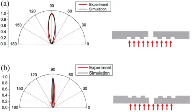
In addition to this, we investigated which surface is responsible for the beaming effect and designed a circular aperture with grooves on only one of the sides of the metal block. The angular distributions of EM waves transmitted through different sides are shown in Figure 11. These results show that when we illuminate the sample on the side of a grooved surface (no grooves on the exit surface), we could not observe a beaming effect. On the other hand, when the sample is illuminated on the side of the flat surface such that the output surface is grooved, a beaming effect occurs. Figure 10 Normalized angular transmission distribution for (a) Sample
3 and (b) Sample 4 at the resonance frequency (13 GHz)
Figure 11 Normalized angular transmission distribution for one-sided grooved samples at the resonance frequency. The orientation of the samples given in the right of the graphs. [Color figure can be viewed in the online issue, which is available at www.interscience.wiley.com]
Figure 9 Normalized angular transmission distribution for (a) Sample 1 and (b) Sample 2 at the resonance frequency (13 GHz)
This can only be interpreted as only the output surface being responsible for the beaming effect.
We studied, lastly, the dependence of angular distribution to the frequency. We calculated (top) and measured (bottom) the electric field distribution of the transmitted beam from Sample 4 at the resonance and off-resonance frequency with a scan setup. In Fig-ure 12, the calculated electric field distribution of the transmitted beam from Samples 1 and 4 at the resonance frequency (13 GHz) is presented. Figure 13 shows the measured electric field intensity at the resonance frequency and off resonance frequency over a region of a 44⫻ 90 cm2area. The measured electric field intensity
on the output side of the aperture is measured with a monopole antenna with a resolution of 0.5 cm. Our experiment shows that the electric field intensity is confined to a narrow spatial region and propagates without diffracting into a wide angular region at the resonance frequency. The theoretical results are in good agreement with the experimental result. This shows that using a periodically grooved structure at the resonance frequency solves the diffraction problem with the light from the subwavelength apertures, as well as poor transmission.
Such grating structures with a very large transmission and beaming properties have many potential applications in photonic devices. They can be used for high-brightness subwavelength light sources or high-throughput optical switches, as well as, to reduce the beam divergence of light-emitting diodes and semiconductor lasers.
3. CONCLUSION
The main objective of this work can be stated as the investigation of the coupling mechanism between microwave radiation and surface plasmons in 2D metallic grating structures. We presented the measured and calculated results of microwave transmission and angular distribution of the transmitted beam through a sub-wavelength circular aperture with metallic gratings. We presented that these structures are scalable and it is possible to obtain similar results in different frequency regimes. We demonstrated that the beam that was transmitted from the circular apertures surrounded
by concentric periodic grooves has an angular divergence of⫾3°. We presented the measured normalized angular transmission dis-tributions from one sided samples and we observed that only the output surface is responsible for the beaming effect. Furthermore, we showed that it is only possible to observe the beaming effect at the resonance frequency, since at the off-resonance frequency electromagnetic waves are diffracted. As a result, it is possible to enhance and confine light using circular annular aperture with grooves which can be used to construct miniaturized optoelec-tronic circuits with subwavelength components.
REFERENCES
1. H.A. Bethe, Theory of diffraction by small holes, Phys Rev 66 (1944), 163–182.
2. H. Raether, Surface plasmons on smooth and rough surfaces and on gratings, Springer-Verlag, Berlin, 1988.
3. T.W. Ebbesen, H.J. Lezec, H.F. Ghaemi, T. Thio, and P. Wolf, Extraordinary optical transmission through subwavelength hole arrays, Nature 39 (1998), 667– 669.
4. D.E. Grupp, H.J. Lezec, T.W. Ebbesen, K.M. Pellerin, and T. Thio, Crucial role of metal surface in enhanced transmission through sub-wavelength apertures, Appl Phys Lett 77 (2000), 1569 –1571. 5. S.S. Akarca-Biyikli, I. Bulu, and E. Ozbay, Enhanced transmission of
microwave radiation in one-dimensional metallic gratings with sub-wavelength aperture, Appl Phys Lett 85 (2004), 1098.
6. T. Thio, K.M. Pellerin, R.A. Linke, H.J. Lezec, and T.W. Ebbesen, Enhanced light transmission through a single subwavelength aperture, Opt Lett 26 (2001), 1972.
7. M.J. Lockyear, J.R.A.P. Hibbins, and C.R. Lawrence, Surfacetopog-raphy-induced enhanced transmission and directivity of microwave radiation through a subwavelength circular metal aperture, Appl Phys Lett 84 (2004), 2040.
8. H. Caglayan, I. Bulu, and E. Ozbay, Extraordinary grating-coupled microwave transmission through a subwavelength annular aperture, Opt Express 13 (2005), 1666 –1671.
9. F.J. Garcia-Vidal, L. Martin-Moreno, H.J. Lezec, and T.W. Ebbesen, Figure 12 The electric field distribution calculated for (a) Sample 1 and
(b) Sample 4. Sample 4 optimizes the angular divergence of the beam since FWHM divergence of the beam is reduced fourfold compared to the beam transmitted through a subwavelength aperture (Sample 1). [Color figure can be viewed in the online issue, which is available at www. interscience.wiley.com]
Figure 13 (a) The electric field distribution measured for Sample 4 at the resonance frequency (b) The electric field distribution measured for Sam-ple 4 at the off-resonance frequency. [Color figure can be viewed in the online issue, which is available at www.interscience.wiley.com]
Focusing light with a single subwavelength aperture anked by surface corrugations, Appl Phys Lett 83 (2003), 4500 – 4502.
10. H.J. Lezec, A. Degiron, E. Devaux, R.A. Linke, L. Martin-Moreno, F.J. Garcia-Vidal, and T.W. Ebbesen, Beaming light from a subwave-length aperture, Science 297 (2002), 820 – 822.
11. L. Martin-Moreno, F.J. Garcia-Vidal, H.J. Lezec, A. Degiron, and T.W. Ebbesen, Theory of highly directional emission from a single subwavelength aperture surrounded by surface corrugations, Phys Rev Lett 90 (2003), 167401.
12. H. Caglayan, I. Bulu, and E. Ozbay, Beaming of electromagnetic waves emitted through a subwavelength annular aperture, J Opt Soc Am B 23 (2006), 419 – 422.
13. U.C. Fischer and M. Zapletal, The concept of a coaxial tip as a probe for scanning near field optical microscopy and steps towards a real-isation, Ultramicroscopy 42/44 (1992), 393–398.
14. F.I. Baida and D.V. Labeke, Light transmission by subwavelength annular aperture arrays in metallic films, Opt Commun 209 (2002), 17–22.
15. F.I. Baida, D.V. Labeke, and B. Guzial, Enhanced con ned light transmission by single subwavelength apertures in metallic films, Appl Opt 42 (2003), 6811.
16. User Manual Version 5.0 (CST GmbH, 2005). © 2006 Wiley Periodicals, Inc.
CIRCUIT MODEL AND DESIGN OF
SILICON-INTEGRATED CRLH-TLS
ANALOGICALLY CONTROLLED BY
MEMS
Julien Perruisseau-Carrier,1Thomas Lisec,2and
Anja K. Skrivervik1
1Laboratory of Electromagnetics and Acoustics (LEMA)
Ecole Polytechnique Fe´de´rale de Lausanne (EPFL) Switzerland
2Fraunhofer Institute for Silicon Technology
Itzehoe Germany
Received 24 May 2006
ABSTRACT: We present an integrated composite right/left handed
trans-mission line (CRLH-TL) phase shifter analogically controlled by means of a MEMS series capacitor. The device is based on coplanar waveguide (CPW) technology and operates at a central frequency of 18 GHz. An accurate and physical circuit model including parasitics inherent to this MEMS realiza-tion is presented. We describe the method used to design the presented structure, which consists in a mixed approach using the developed circuit model and full-wave simulations. The MEMS-controlled CRLH-TL has been fabricated and characterized, showing good agreement with pre-dicted performances. © 2006 Wiley Periodicals, Inc. Microwave Opt
Technol Lett 48: 2496 –2499, 2006; Published online in Wiley Inter-Science (www.interscience.wiley.com). DOI 10.1002/mop.22014 Key words: composite right/left handed transmission line;
metamate-rial; microelectromechanical system; periodic structure; phase shifter
1. INTRODUCTION
The composite right/left handed transmission line (CRLH-TL) structure is a particular class of metamaterial, which consists in lumped “dual ” elements (shunt L and series C) loading a classical right-handed transmitting medium [1, 2]. In contrast with metamaterials relying on the resonance of geometrical structures such as arrays of metal wires and split ring resona-tors, the CRLH-TL is an inherently wideband structure well suited to phase shifting applications. In this context, it has
recently attracted significant interest, and different one-dimen-sional devices based on this principle have been demonstrated, such as leaky-wave antennas [3] and phase shifters used for instance in series feed network of antenna arrays [1, 4] or compact dual-band couplers [2].
In this letter, we propose to realize silicon-integrated CRLH-TL phase shifters controlled by means of microelectromechanical sys-tems (MEMS). In recent years, the rapid development of MEMS technology allowed challenging radically the performances of par-ticular variable phase shifters in terms of insertion loss, drive power, monolithic integration, and cost. Examples of demonstrated MEMS-based variable phase shifters are the distributed MEMS transmission line (DMTL) [5] and the reflection-type phase shifter [6], which exhibit true-time and constant-phase delays, respec-tively.
The aim of this work is thus to apply the aforementioned benefits of MEMS technology to a 1D CRLH-TL structure. From a more general perspective, it is believed that most demonstrated CRLH-TL-based microwave devices [1– 4] could benefit from MEMS technology and especially from the state-of-the-art tunabil-ity capabiltunabil-ity it offers.
The CRLH-TL phase shifter presented here is based on copla-nar waveguide (CPW) technology and variability is achieved by means of a MEMS series capacitor used as the loading element of the CRLH-TL. It is shown that in this case, the circuit model of the CRLH-TL must include several parasitics to account precisely for the behavior of the actual device. A mixed approach using full-wave simulations and a comprehensive circuit model is employed to design the MEMS phase shifter. Finally, fabricated devices are measured to validate the presented modeling and design method-ology.
2. PRINCIPLE AND IMPLEMENTATION
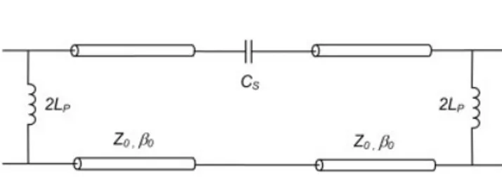
The model of a possible unit cell of an ideal CRLH-TL is depicted in Figure 1. It is well known that such a structure exhibits right and left-handed bands, corresponding to phase velocities parallel and antiparallel with the group velocity, respectively. For practical applications, it is useful to achieve phase shift continuity at a frequency of 0° phase shift, referred to here as f0, which corre-sponds to the transition between right and left-handed bands. The condition on the ideal circuit parameters to achieve this phase continuity is Z0 ⫽
冑
LP/CS, with Z0, Lp, and Csas defined in Figure 1 [1, 7]. In this work, we propose to achieve variability by controlling the series capacitor Cs while letting Lp fixed. As a result, it is obvious that perfect phase continuity will not be achieved in all MEMS states. Nevertheless, this approach is suf-ficient if Cs is varied of a small relative amount and it will be shown that this results in satisfactory phase continuity within the whole range of analog variation of the MEMS series capacitance value.Figure 2 shows a 3D view of the presented phase shifter and the principle of the MEMS series capacitor can be understood from the inset of the figure; the overall series capacitance depends on the interdigited capacitor in the central conductor of the CPW, but also