www.advmattechnol.de
Modification of Mesoporous LiMn
2
O
4
and LiMn
2−x
Co
x
O
4
by SILAR Method for Highly Efficient Water Oxidation
Electrocatalysis
Irmak Karakaya, Ferdi Karadas, Burak Ulgut, and Ömer Dag*
DOI: 10.1002/admt.202000353
in recent years.[6–11] However, cobalt is a
toxic, and relatively low abundant element that needs to be changed with a more abundant and less toxic element, such as manganese. Manganese oxides and mixed oxides have also been investigated that dis-played a lower OER efficiency and lower stability.[12–17] Most studies show that the
cobalt is a key element for an efficient OER such that incorporation of cobalt into manganese oxide lattice improves the OER efficiency and stability of a modified electrode.[17]
Mesoporous metal oxides have been targeted as efficient electrocatalysts for the OER. Several synthetic proto-cols, including hard and soft templating methods have been developed to produce mesoporous metal oxides.[21–27] Hard
tem-plating method typically uses ordered mesoporous silica or carbon as a mold to produce ordered mesoporous metal oxide powders.[24,25]Soft templating methods, such as
evapo-ration induced self-assembly[23] and molten salt assisted
self-assembly (MASA)[24–27]processes, have been developed for the
fabrication of mesoporous metal oxide thin films that would be more practical in an electrochemical process. The MASA process is a more applicable method to produce disordered mesoporous transition metal oxides of metals that do not have alkoxide precursors; the metal precursors used in this pro-cess are usually metal nitrate, metal acetate, or metal chloride salts.[24–27] In the MASA process, a transition metal salt that has
low melting point (such as first raw transition metal nitrates) or high solubility (such as most lithium salts) could be used as a solvent to assemble surfactant molecules into a lyotropic liquid crystalline mesophase.[28–31] Salt is in a molten phase in
the mesophase (confined nanospace in hydrophilic domains) due to nanospace effect (NE).[30] The NE, not only reduces the
melting point of the salts,[30] also enhances the solubility of the
salts.[31] Moreover, presence of two salts (lithium and transition
metal salts) creates a synergistic effect that further improves the stability and high salt uptake of the salt-surfactant meso-phases. Coating of a mesophase as a thin film and its calcina-tion at elevated temperatures produce mesoporous metal oxide thin films.[26–38] The MASA process has already been employed
to two groups of metal oxides. In the first group, a silica or titania precursor is used as a polymerizing agent at room tem-perature together with a transition metal nitrate salt to produce
Iridium, ruthenium, and cobalt oxides are target materials as efficient and stable mesoporous metal oxide electrocatalysts for oxygen evolution reac-tion (OER). However, they are costly, toxic, and not practical for an efficient OER process. Here, a two-step method is introduced, based on earth-abundant manganese; molten salt-assisted self-assembly process to pre-pare mesoporous LiMn2−xCoxO4 (x = 0–0.5) modified electrodes, in which
a systematic incorporation of Co(II) into the structure is performed using successive ionic layer adsorption and reaction followed by an annealing (SILAR-AN) process. Applying SILAR-AN over a stable m-LiMn1.6Co0.4O4
elec-trode improves the OER performance; the Tafel slope and overpotential drop from 66 to 46 mV dec−1 and 304 to 265 mV (at 1.0 mA cm−2), respectively. The performance of the modified electrodes is comparable to benchmark IrO2 and
RuO2 catalysts and much better than cobalt oxide electrodes. Electronic
inter-actions between the neighboring Mn and Co sites synergistically amplify the OER performance of the m-LiMn2−xCoxO4 electrodes. The data are compatible
with an eight steps nucleophilic acid-base reaction mechanism during OER.
I. Karakaya, Prof. F. Karadas, Prof. B. Ulgut, Prof. Ö. Dag Department of Chemistry
Bilkent University Ankara 06800, Turkey E-mail: [email protected]
Prof. F. Karadas, Prof. B. Ulgut, Prof. Ö. Dag
UNAM – National Nanotechnology Research Center and Institute of Materials Science and Nanotechnology
Bilkent University Ankara 06800, Turkey
The ORCID identification number(s) for the author(s) of this article can be found under https://doi.org/10.1002/admt.202000353.
1. Introduction
Oxygen evolution reaction (OER) electrocatalysts are impor-tant group of materials that may replace currently used expen-sive platinum electrodes. Transition metal oxides and metal sulfides with high surface area are the target materials in the literature.[1–20] Although IrO
2 and RuO2-based electrodes are
the benchmark catalytic systems, they are precious metals, which limits their applications in scalable devices.[3–5] 3d metal
oxides, particularly cobalt oxides can be considered as alterna-tive class of catalysts for the OER process.[6–11] For an efficient
mesoporous silica-metal oxides (such as CdO/SiO2 and ZnO/
SiO2)[26] or metal titanates (such as MnTiO3, CoTiO3, CdTiO3,
Zn2TiO4, and Li5Ti4O12).[27,28] In the second group, a clear salt(s)
and nonionic/cationic surfactants solution is coated to produce a stable thin film of an lyotropic liquid crystalline (LLC) meso-phase. Aging the mesophase at room temperature (RT) does not alter the stability or structure. Moreover, calcination of the LLC phase produces the mesoporous metal oxide film of the salt; the mesoporous LiMn2O4, LiMn2−xCoxO4, LiCoO2, and NiO
thin films have recently been synthesized as a second group of metal oxides.[17,24,25]
Successive ionic layer adsorption and reaction (SILAR) method has also been an effective method to modify porous materials[32] either growing special coatings layer by layer or
quantitatively introducing/controlling dopant(s) over surfaces to alter, protect, and/or functionalize the surface of the modi-fied materials.[33–35] Furthermore, the SILAR method has been
employed to coat electrode surfaces by another compound(s) to either change the surface properties or to protect the surface in an electrochemical process. A multilayered material could be fabricated by SILAR that is followed by an annealing step (SILAR-AN) or a chemical reaction (SILAR-CR). For instance, in quantum dot sensitized solar cell, the SILAR-CR method has been successfully employed to slow/stop reduction reac-tion (counter-reacreac-tion) on the anode surface in a quantum dot sensitized solar cells.[34] SILAR-CR and SILAR-AN are simple
and effective methods to adsorb ions over a material surface for a further reaction or thermal treatment, respectively, to coat an atomically thin layer(s) of active and/or protective spe-cies over the thin films and also to produce core–shell nano-particles as electrodes for various applications.[32–35]
Here, we employed both MASA and SILAR-AN methods to produce mesoporous LiMn2−xCoxO4 thin films as an efficient
electrocatalyst for OER with relatively low cobalt content. The MASA and SILAR-AN methods were employed to produce stable mesoporous thin films of cobalt enriched LiMn2−xCoxO4
(x = 0–0.5) electrodes that have excellent stability and high effi-ciency in the OER in an alkali media. The motivation of this work is to improve the stability and efficiency of manganese (less toxic and more abundant) rich mesoporous LiMn2−xCoxO4
electrodes for OER processes.
2. Results and Discussion
2.1. Synthesis and Characterization of Mesoporous LiMn2−xCoxO4 Electrodes
In the fabrication of mesoporous LiMn2−xCoxO2
(m-LiMn2−xCoxO4) electrodes and their modifications using a
small amount of cobalt have been carried by using two different synthesis protocols. In the first protocol, a previously estab-lished MASA[17] process has been employed to produce the thin
film electrodes over the fluoride doped thin oxide (FTO)-coated glass substrates (m-LiMn2−xCoxO4). Simply, a clear MASA
solu-tion (LiNO3, [Mn(H2O)4](NO3)2, [Co(H2O)6](NO3)2, P123, CTAB,
HNO3 and ethanol) was spin-coated over FTO-coated glass and
calcined at 300 °C to obtain the thin-film electrode (denoted as m-LiMn2−xCoxO4), see ref. [17] for details. SILAR-AN has been
employed multiple times to modify those electrodes (denoted as m-LiMn2−xCoxO4-#) in the second protocol.
The cobalt-free m-LiMn2O4 electrode has a typical Burret–
Emmett–Teller (BET) surface area of 98 m2 g−1. The BET
sur-face area gradually increases up to 144 m2 g−1 with increasing
cobalt in the m-LiMn2−xCoxO4 sample (x is 0.5). Also note
that further increasing cobalt reduces the surface to 124 and
103 m2 g−1, as recorded from m-LiMnCoO
4 and
m-LiMn0.5Co1.5O4, respectively.[17] The increase in the surface
area in the presence of two salts could be related to synergic effects of two molten salts in the LLC media. Note that while one salt-surfactant mesophases have limited stability against salt leach out; presence of a second even a third salt stabilizes the salt-surfactant LLC mesophase at much higher salt con-centrations.[36] Furthermore, it has been previously shown that
the pore-walls are nanocrystalline at all compositions with a typical crystallite size of 5–6 nm (as predicted from Scherrer’s equation using X-ray diffraction (XRD) data, transmission elec-tron microscopy (TEM) images).[17] However, the surface area
of the films gradually decreases with increasing calcination/ annealing temperature; such as it is 90, 69, and 33 m2 g−1 at
400, 500, and 600 °C, respectively, in the m-LiMn2O4.[17] The
electrochemical behaviors and water oxidation electrocata-lytic performance of these electrodes have also been investi-gated in our previous work using m-LiMn2−xCoxO4 electrodes,
where x is 0, 0.5, 1.0, 1.5, and 2.[17] The m-LiMn
2O4 electrode
has a high Tafel slope (130 mV dec−1) and high overpotential
(417 mV at 1 mA cm−2 and 541 mV at 10 mA cm−2) and low
stability during chronopotentiometry (CP) experiments in 1 m KOH solution. However, introducing a 25 mole% cobalt (m-LiMn1.5Co0.5O4) improved the electrocatalytic performance
(such as the Tafel slope dropped to 66 mV dec−1 with
overpo-tentials of 300 and 367 mV at 1 and 10 mA cm−2 current
den-sities, respectively, after IR compensation[17]) and the stability
of the m-LiMn1.5Co0.5O4 electrode. In higher cobalt-containing
electrodes (m-LiMn2−xCoxO4, where x is larger than 0.5), these
values slightly improved up to 64 mV dec−1 for the Tafel slope
and 280 and 345 mV at 1 and 10 mA cm−2, respectively, for the
overpotentials in the m-LiMnCoO4 electrode.[17] Extra
overpo-tentials add up to these values at higher current densities due to the electrode resistance that mostly originates from FTO.[17]
The typical resistance of the electrode on FTO varies from 15 to 20 Ω and adds extra 150–200 mV at 10 mA cm−2 and 1.5–2.0 V
at 100 mA cm−2 current densities, see Figure S1a (Supporting
Information). Replacing FTO with a graphite substrate (0.7 mm diameter pencil tips, which are pressed graphite, calcined at 300 °C, prior to use) improves the overpotential values at high current densities. The overpotential drops from 1277 to 523 mV at 60 mA cm−2 by simply using a better conducting substrate,
such as graphite, see Figure S1b (Supporting Information). The overpotential versus current density plot of the graphite coated m-LiMnCoO4 electrode is also linear with a slope of 3.77 Ω. The
origin of these losses is mostly from IR drop due to electrode resistance. The estimated overpotential in the graphite coated electrode at 60 mA cm−2 current density (from the Tafel
equa-tion, η = a + blog(j), where η is overpotential, b is the Tafel slope, and j is the current density) is around 398 mV but the observed value is 523 mV. The resistance of the graphite-coated electrode is estimated to be around 2.08 Ω (calculated from
Ohm’s law (523–398) mV 60 mA−1). The same calculation gives
an FTO-coated electrode resistance of 17.7 Ω (1.460–398)/60), however, the resistance that can be evaluated from the over-potential versus current density plot is 19.01 Ω, see Figure S1 (Supporting Information). The difference is remarkably similar, 1.69 (=3.77–2.08) and 1.31 (=19.01–17.7) Ω in both graphite- and FTO-coated electrodes, respectively, and must be related to the rate of OER over these two electrodes. The major limitation of the m-LiMn2−xCoxO4 electrodes in the OER originates from
highly resistive substrates. The potential losses at high current densities are purely ohmic.
Besides the conductivity advantage of graphite, there are also some disadvantages to using graphite as a substrate in terms of fabricating the electrodes. It is more difficult to control the thickness/amount of m-LiMn2−xCoxO4 films by dip-coating
graphite rods using clear homogeneous MASA solutions, but this problem could be overcome by using graphite-plates. Moreover, the dip-coating method produces: nonuniform film thickness and is usually employed to prepare thicker films that may elevate the OER performance (more electrocatalyst) but increasing the thickness of the electrode will also increase the electrode resistance that will lower the EOR performance at high current densities. To overcome these issues and be able to compare the results from both substrates, the graphite elec-trodes were coated by using 10 times diluter MASA solutions; dilution also ensures a thinner film over the graphite surface. The cyclic voltammetry (CVs) of FTO- and graphite-coated elec-trodes (Figure S1, Supporting Information) clearly show that the graphite-coated electrode is even thinner than the FTO-coated electrode as evidenced by lower current density in the oxidation/reduction peaks from the electrode surface of the graphite-coated electrode, see Figure S1a (Supporting Informa-tion). Overall, a better conducting substrate is more beneficial for its use in practical applications.
In this investigation, we took the electrodes with modest cobalt content (such as m-LiMn2O4, m-LiMn1.9Co0.1O4,
m-LiMn1.8Co0.2O4, m-LiMn1.7Co0.3O4, and m-LiMn1.6Co0.4O4
elec-trodes) with decent stability in the alkaline media and improve their electrocatalytic performance and stability by employing SILAR-AN method. All the measurements were carried out using the electrodes prepared over the FTO surface to be able to com-pare the electrodes with each other. Note also that all the thin-film electrodes (m-LiMn2−xCoxO4 (x = 0–0.5)) over the FTO electrodes
weigh around 0.1 mg with a typical thickness of around 400 nm.
Figure 1 shows a schematic representation of the SILAR-AN
(modification) process. First, m-LiMn2O4 electrode was
modi-fied to obtain 4 new m-LiMn2O4-# (# is the number of
SILAR-AN employed and is 1, 3, 5, and 7) electrodes and characterized by using XRD technique. In each coating, the SILAR coating
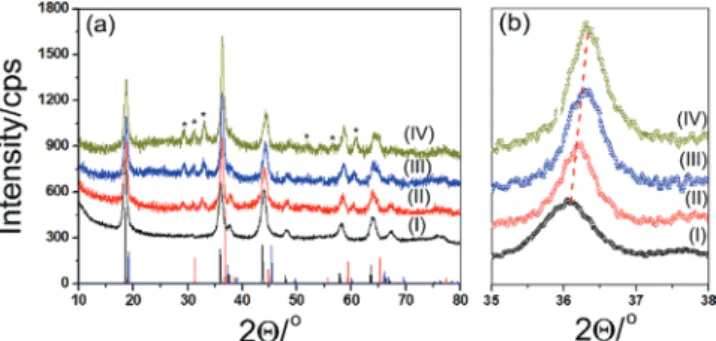
was followed by a good washing and annealing/calcination pro-cess at 300 °C before going to the next coating or using as an electrode to ensure homogeneous cobalt coatings. Figure 2 shows a series of powder X-ray diffraction (PXRD) patterns of the modified samples together with reference data of bulk LiMn2O4,
LiCoO2, and Co3O4 to identify whether the cobalt ions diffuse into
walls or it deposits as a thin layer of cobalt oxide over the pore-walls. The PXRD patterns of the m-LiMn2O4 (it can be indexed
to spinel structure) and their modified versions (m-LiMn2O4-#,
where # is 1, 3, 5, and 7) are remarkably similar. However, all the diffraction lines slightly shift to higher angles, maybe indi-cating a homogeneous mixing (solid-solution) of cobalt into the m-LiMn2O4 spinel structure, see Figure 2b. The XRD patterns
were compared with the PDF cards of possible products, Co3O4
(PDF 00-042-1467) and LiCoO2 (PDF 00-044-0145) to shed light on
how the annealing proceeds. However, the PDF cards of Co3O4,
LiCoO2, and m-LiMn2−xCoxO4 are very similar to each other,
there-fore it is difficult to determine whether the cobalt is forming its oxide or reacting with the m-LiMn2O4 to form m-LiMn2−xCoxO4
from the XRD data, see Figure 2. Employing the SILAR-AN pro-cess multiple times and further annealing the samples at higher temperature provide extra but weaker diffraction lines that can be indexed to crystalline Mn3O4 nanoparticles (PDF-00-024-0734 card
of bulk Mn3O4). It means that cobalt species over the pore-wall
surface diffuse into the m-LiMn2O4 pore-walls and undergo an
exchange reaction with manganese ions that, with further heating, form its own oxide phase (Mn3O4) over the pore-walls and likely
on top of the film/electrode surface, see latter.
We also recorded high-resolution X-ray photoelectron spec-troscopy (XPS) data of the electrodes (over the FTO glass, top electrode surface) and their grind powders (obtained by scraping the electrode and grinding) of the m-LiMn2O4-#
(# = 0, 1, 3, 5, and 7) and m-LiMn2−xCoxO4, see Figure 3; and
Figures S2–S4 (Supporting Information), in the O 1s, Co 2p,
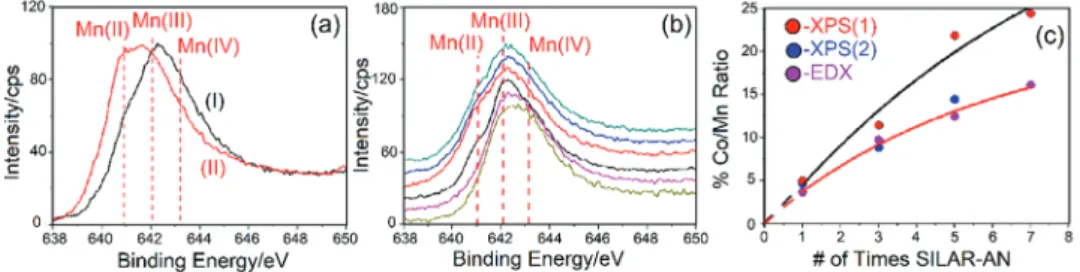
and Mn 2p regions. The spectrum of m-LiMn2O4 in the Mn
2p (2P
3/2) region consist of a peak at 643 eV due to Mn4+ sites
with a shoulder on the low energy side due to Mn3+ sides,
characteristic for spinel LiMn2O4.[37] The Mn 2p spectrum of
the m-LiMn1.5Co0.5O4 film is very similar to m-LiMn2O4,
indi-cating a solid solution formation in the m-LiMn1.5Co0.5O4 in
terms of Mn3+/Mn4+ sides in the structure. With increasing
cobalt in the m-LiMn2O4 sample, the Mn 2p (2P3/2) peaks
grad-ually shift to a lower binding energy, indicating the presence/ formation of Mn species with a lower oxidation state in the
Figure 1. Schematic representation of the SILAR-AN process: (I) Dipping
into 1 m Co2+ solution and washing and (II) anneling.
Figure 2. PXRD patterns of m-LiMn2O4-# a,b), where # is (I) 0, (II) 1,
(III) 3, and (IV) 5 (the reference data in panel a): black lines-LiMn2O4, blue
modified samples. The difference spectrum of the m-LiMn2O4
and modified LiMn2O4-# clearly shows that the intensity of the
low energy side of the main 2P
3/2 peak increases and the high
energy side decrease (see Figure S3a, Supporting Information), supporting the above statement. The line shape in the Mn
2P
3/2 region closely resembles the spectrum of Mn3O4[38] (see
Figure S2c, Supporting Information). Both XRD and XPS data collectively show the formation and accumulation of Mn3O4
particles over the electrode surface. We also collected energy dispersive X-ray (EDX) data of these samples and found out that the cobalt amount in the samples gradually increases with multiple coatings, the cobalt amount increases from 3.5 mole% in the LiMn2O4-1–16 mole% in the LiMn2O4-7 film,
see Figure S5a,b (Supporting Information). The plot of the rela-tive amount of cobalt deposited with respect to the number of coating gradually increases and converges to a value around 22 mole%, see Figure S5b (Supporting Information).
The surface area was also measured and calculated using
N2 adsorption–desorption isotherms and BET method, see
Figure S6 and Table S1 (Supporting Information). Like the elemental analysis, the surface area calculated from the BET equation drops by 30% after the 7th coating. Notice also that there is sharp surface area drop (from 98 to 75 m2 g−1), a larger
pore (from 12.8 to 21.3 nm, calculated from Barrett–Joyner– Halenda equation using desorption isotherm) and pore volume expansions (from 0.32 to 0.43 cm3 g−1) in the first coating,
how-ever, further coatings dropped the BET surface area, changed the pore size and pore volume in less extend (see Table S1, Sup-porting Information). The data show that SILAR-AN coating is uniform and applicable to modify existing mesoporous materials.
Scanning electron microscopy (SEM) images of the
m-LiMn2O4 and modified m-LiMn2O4-# films were also
recorded to elucidate the details of surface morphology. Surface morphology of the films is unaltered up to 3rd coating, but indi-vidual nanoparticles appear in 5th coating and dominate over the surface with further coatings, see Figure S6 (Supporting Information).
XPS data were further analyzed to elucidate the composi-tional and morphologic changes in the internal and external surface of the electrodes by increasing cobalt content by employing SILAR-AN modification and MASA methods. The O 1s region displays multiple features at 529.9 (a peak) and 531.2 eV (a shoulder) tailing down to 533 eV that show drastic changes with increasing cobalt loading over the electrode top surface, see Figure S2a (Supporting Information). As shown
in Figure S2a (Supporting Information), the shoulder at 531.2 eV gradually increases up to 5th loading. The peak at 529.9 eV (peak I) is due to lattice oxygens and the other features at 530.7 (peak II), 531.2 (peak III), and 532.3 eV (peak IV) have been assigned to hydroxy, peroxy, and coordinated water oxy-gens,[39,40] respectively, see Figures S2a, S3b, and S4 (Supporting
Information). With cobalt loading, while the Co 2p region shows no response other than a gradual increase in intensity, the O 1s peaks follow the trend in Mn 2p region. The signals in the Co 2p (2P
3/2) region are relatively weaker and broader in
the spectra of the electrode surface (see Figure S2b (Supporting Information). The Co 2p spectra of the modified m-LiMn2O4
electrodes display a broad peak at 780.2 eV with a satellite peak at 786 eV. However, the spectrum of the grind samples displays a relatively sharper peak at around 780.5 eV with a satellite peak at 790 eV, see Figure S2c (Supporting Information). The satel-lite peak of Co(II) species appears at 786 eV and Co(III) and Co(IV) species at 790 eV.[41] As shown, the main 2P
3/2 peak is
not very sensitive to the oxidation state of the cobalt species, the satellite peaks are very sensitive and commonly used to iden-tify the oxidation state of cobalt species.[41] Therefore, it is
rea-sonable to suggest that while the electrode surface is rich with Co(II) species, the interior surface is modified by Co(III) and/or Co(IV) species in the SILAR-AN process. Moreover, the Co 2p spectra of all grind samples are like m-LiMn2−xCoxO4. This
concludes that Co incorporates into m-LiMn2O4 and produces
m-LiMn2−xCoxO4 on the pore-walls. However, there is some
accumulation of Co(II) species over the electrode surface. This is also clearly visible in the % Co/Mn versus number of loading plots in Figure 3c, see later.
Figure 3a compares the Mn 2p (2P
3/2) region of the
elec-trode surface and grid powder upon 3 consecutive SILAR-AN processes. The shoulder on the low energy side (due to Mn2+ species) becomes the most intense peak in the spectra
of the electrode surfaces (Figure S2c, Supporting Informa-tion) while the scraped and grind powder samples display no change (see Figure 3b) with multiple loading. The top surface of the m-LiMn2O4-3 and m-LiMn2O4-5 electrodes have similar
spectra, see Figure S2d (Supporting Information), supporting our above proposal. The amount of Mn2+ species is more over
the electrode surface, indicating that crystalline Mn3O4 (Mn(II)
Mn(III)2O4) species are accumulating over the electrode
sur-face, see Figure 3a.
As a result of these observations, we suggest the following redox reactions (see Equations (1) and (2)) between the Co(II) ions on the surface and m-LiMn2O4 during the modification Figure 3. Mn 2p XPS spectra of: a) grind sample of m-LiMn2O4-3 (I) and the electrode top surface (II), b) bottom to top: m-LiMnCoO4 (olive),
m-LiMn1.5Co0.4O4 (pink), and m-LiMn2O4-# (# is 0 (black), 1 (red), 3 (blue), and 5 (green)), and c) percent Co/Mn from XPS (electrode surface, XPS(1)
process to alter the electrode internal and external surface. Comparison of all the XPS data suggest that after 5th loading, the small pores get plugged (as also observed in the N2
adsorp-tion–desorption isotherms) by the out coming manganese species (likely Mn3O4 nanoparticles) that accumulate over the
electrode surface and no more appreciable loading is possible after 5th loading Co NO s /3 Co O s 2 /3 NO g 2 /3 N O g 3 2 3 4 2
( )
2 5( )
( )
(
(
)
) ( )
→(
)
( )
+ + x x x x (1) m LiMn O s /3 Co O s m LiMn Co O s /3 Mn O s 2 4 3 4 2 4 3 4( )
( )
( )
( )
( )
( )
− + → − − + x x x x (2) Figure 3c shows 3 plots obtained from the XPS of grind powers and electrodes surface and EDX data. Clearly EDX data show the bulk composition of the samples. However, the XPS data provide compositional information of the top few layers of the material. The plot of percent Co/Mn versus the number of SILAR-AN of both XPS and EDX of data of the grind sam-ples overlap with each other. Therefore, the XPS data of the grind samples provide more information about the internal surface of the electrodes, while the XPS of the electrode sur-face provides information on the top sursur-face of the electrodes. Both XPS and EDX data of the grind samples collectively show that the SILAR-AN is an effective method to homogeneously coat the internal surface of the m-LiMn2−xCoxO4 thin films.The plot of %Co/Mn from XPS data of the electrode surface linearly increases with the increasing number of SILAR-AN process. Therefore, the electrode surface becomes richer with Mn(II) and Co(II) species with further coatings.
Further analysis of the O 1s spectra of the electrodes and ground powders provide some insightful information on the surface composition of the internal versus external surface of the electrodes, see Figures S2a and S3b (Supporting Informa-tion). The peaks due to peroxide (MOOH) and hydroxide (MOH) species increase with an increasing number of applied SILAR-AN over the top surface of the electrodes (see Figure S2a, Supporting Information). However, this is not the case on the internal surface of the electrodes; there is almost no change in the oxygen composition by increasing the number of loading in the interior of the electrodes. Figure S4 (Supporting Information) also displays O 1s spectra of 3 m-LiMn2−xCoxO4 unmodified grind samples. Clearly, with
increasing Co in the m-LiMn2−xCoxO4 grind powder, the
sur-face hydroxy, peroxy, water species increases. The modified electrodes are rich with hydroxy and peroxy species, while the unmodified ones are rich with water. It is reasonable to con-clude that increasing cobalt at the surface and/or in the pore-walls increases the surface concentration of highly reactive hydroxide and peroxide species for the oxygen evaluation reac-tion, see later. Moreover, the SILAR-AN modification enhances the formation of Mn3O4 over the electrode surface, the cobalt
preferentially modifies and enhances the cobalt amount in the pore-walls. Therefore, the top surface of the pore-walls (inte-rior surface) has cobalt rich MnCo oxide, hydroxide, per-oxide, and water surface species that are collectively involved in the catalysis of water oxidation process, see later.
2.2. Electrochemical Behaviors of the m-LiMn2−xCoxO4 and
m-LiMn2−xCoxO4- # Electrodes
Modification of the m-LiMn2O4 electrodes by SILAR-AN in
mul-tiple steps produces a cobalt rich pore surface in m-LiMn2O4-#
electrodes. To test the modified electrodes, a detailed electro-chemical characterization has been carried by first recording CVs of each electrode and compared with the bare m-LiMn2O4
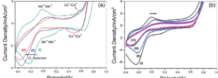
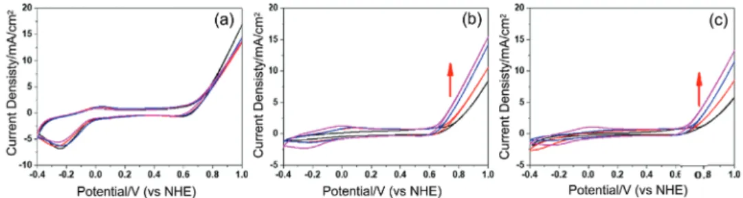
electrode with respect to OER efficiency. The CVs of the m-LiMn2O4, m-LiMn1.5Co0.5O4, and m-LiMnCoO4 electrodes in
1 m KOH solution are shown in Figure 4. The features in the forward scan in the −0.4–0.2 V region, have been assigned to oxidation of manganese from 3+ to 4+,[42–44] and the peak, at
around 0.57 V (becomes visible in the m-LiMnCoO4 sample)
corresponds to the oxidation of cobalt from 3+ to 4+.[45] A sharp
increase after 0.8 V is due to catalytic water oxidation process. The reduction cycle reverses these processes and an intense
and broad oxygen reduction peak[46]is observed at around
−0.3 V, see Figure 4a.
Figure 4b displays the CVs of the modified m-LiMn2O4-#
electrodes. The manganese oxidation/reduction current den-sity decreases with modification, while no significant change in the cobalt redox region is observed. More importantly, there is a change in the OER potential range with modification; kinetics of the process improves with increasing amounts of modification. The current density at 1 V reaches 20 mA cm−2
in m-LiMn2O4-1 electrode, showing the effectiveness of the
SILAR-AN process, see Figure S8 (Supporting Information). One would expect that each modification will improve the elec-trocatalytic activity due to increasing cobalt loading on the sur-face. However, the slope of the current density versus potential curve gradually declines by further increasing the number of loading in the m-LiMn2O4-# electrodes, see Figure S8
(Sup-porting Information). Remember also that we previously estab-lished the formation of the Mn3O4 species on the surface with
increasing the loading numbers. Contaminating/covering the surface with a less active Mn species and decreasing the surface area (also evidenced from the current density drop in the CVs, see Figure 4b) could be the origin of such decrease in the cur-rent density with further loading.
Tafel slopes were evaluated using each modified electrode, see Figure S9 (Supporting Information). The Tafel slopes and overpotentials were extracted from 6 h CP experiment at a current density of 1 mA cm−2, see Table 1. There is a definite
improvement on the Tafel slope in the m-LiMn2O4-1 electrode
(it decreases from 130 for the m-LiMn2O4 to 82 mV dec−1 for
Figure 4. CVs of a) m-LiMn2O4 (I), m-LiMn1.5Co0.5O4 (II), and m-LiMnCoO4
(III) in 1 m KOH solution (x-axis was calibrated with respect to NHE) and b) modified electrodes (m-LiMn2O4-# (# is 1 (I), 3(II), 5 (III), and 7 (IV)).
the m-LiMn2O4-1 electrode), but further coating/loading
gradu-ally increases the Tafel slope up to 108 mV dec−1, recorded for
the m-LiMn2O4-7 electrode. It is likely that the m-LiMn2O4-7
electrode surface is covered with Mn3O4 particles. Notice also
that the overpotential values also follow the same trend, see Table 1. These results are consistent with our proposal, such that the surface becomes Mn3O4 enriched in further coatings.
Furthermore, the effects of calcination/annealing tempera-ture and composition (m-LiMn2−xCoxO4, x = 0.1–0.5) to the
performance and long-term stability of the electrodes were also investigated. Increasing annealing temperature of m-LiMn2O4
improved the crystallinity, which leads to a decrease in the sur-face area from 90 to 69 and to 33 m2 g−1 upon annealing at 400,
500, and 600 °C, respectively. The CVs of the annealed elec-trodes are similar to each other, see Figure S10a (Supporting Information). The Tafel slope is improved from 130 to 128 and to 123 mV dec−1 with increasing annealing temperature from
300 to 400 and to 500 °C, respectively, although the surface area dropped from 98 to 33 m2 g−1. The CP results show that
the performance of the electrode prepared at 400 °C improved slightly upon annealing, see tabulated data in Table 1. Similarly, that of m-LiMn2O4-1 electrode, annealed at various
tempera-tures (300, 400, and 500 °C), also improved, see Table 1. The CV curves were recorded before and after CP measurements at 1 and 10 mA cm−2 current densities, see Figure S10 (Supporting
Information), to check the stability of the electrodes during long-term CP experiments. We found that the m-LiMn2O4 and
m-LiMn2O4-# electrodes are not stable under CP conditions; the
current density in OER range almost disappeared, see Figure 5a. Therefore, increasing the annealing temperature slightly improved the overpotentials but the stability issue remained problem in the m-LiMn2O4-# electrodes.
Since the stability issues of the m-LiMn2O4-# electrodes
could not be resolved by thermal process or modification, we also prepared a series of m-LiMn2−xCoxO4 electrodes and used
for further investigation toward the same goal. It has been
pre-viously shown that the m-LiMn1.5Co0.5O4 electrode (25% Co)
has a good performance and stability in the OER at alkaline conditions, see Figure 5b.[17] To determine the ideal cobalt ratio,
a set of electrodes were prepared by using 5–25% cobalt nitrate in the initial synthesis solutions and the fabricated electrodes were tested for their stability in OER process in alkaline media.
Figure S11 (Supporting Information) shows photographs of a set of m-LiMn2−xCoxO4 (0.1 ≤ x ≤ 0.5) thin films, prepared
over glass substrates. Increasing cobalt amount in the meso-phase (as a result in m-LiMn2−xCoxO4 films) improves the
sur-face smoothness and uniformity of the m-LiMn2−xCoxO4 films,
especially over 10% cobalt (m-LiMn1.8Co0.2O4). SEM images also
show that m-LiMn1.8Co0.2O4 (corresponds to 10% Co) is on the
border between a good quality and nonuniform fragile film, see Figure S12 (Supporting Information). Unstable films con-tain small particles over their surface and their broken edges (cracks) are not as smooth, like the m-LiMn2O4 film. However,
the SEM images show smoother edges in the m-LiMn2−xCoxO4
(x ≥ 0.3), see Figure S12 (Supporting Information). To further evaluate the relationship between the film quality and long-term stability of the electrodes in the OER process, the CVs after various experiments (CP experiments at 1 mA cm−2 for
12 h and 10 mA cm−2 for 6 h) were also recorded (Figure S13,
Supporting Information). Tafel slopes and overpotentials are tabulated in Table 2.
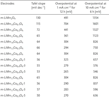
Table 2. Tafel slopes and overpotential results of the m-LiMn2−xCoxO4,
m-LiMn1.6Co0.4O4-#, and m-LiMn1.7Co0.3O4-# electrodes at 1 and 10 mA. Electrodes Tafel slope
[mV dec−1] Overpotential at 1 mA cm−2 for
12 h [mV] Overpotential at 10 mA cm−2 for 6 h [mV] m-LiMn2O4 130 491 1354 m-LiMn1.9Co0.1O4 115 704 1601 m-LiMn1.8Co0.2O4 72 441 1327 m-LiMn1.7Co0.3O4 65 361 1123 m-LiMn1.6Co0.4O4 64 304 826 m-LiMn1.5Co0.5O4 66 294 750 m-LiMn1.6Co0.4O4 64 304 826 m-LiMn1.6Co0.4O4-1 56 325 657 m-LiMn1.6Co0.4O4-3 55 279 576 m-LiMn1.6Co0.4O4-5 53 265 546 m-LiMn1.7Co0.3O4 65 304 826 m-LiMn1.7Co0.3O4-1 56 290 837 m-LiMn1.7Co0.3O4-3 57 283 596 m-LiMn1.7Co0.3O4-5 50 270 636
Table 1. Tafel slopes and overpotentials at 1 mA cm−2 of the m-LiMn
2O4-# electrodes from 6 h CP experiments (*calcined at 300 °C, η-overpotentials). Electrodes* Tafel slope [mV dec−1] η at 1 A cm−2 [mV] Electrodes Tafel slope [mV dec−1] η at 1 mA cm−2 [mV]
m-LiMn2O4 130 491 m-LiMn2O4-400 128 351
m-LiMn2O4-1 82 363 m-LiMn2O4-500 123 582
m-LiMn2O4-3 88 377 m-LiMn2O4-1-400 78 326
m-LiMn2O4-5 89 333 m-LiMn2O4-1-500 61 343
m-LiMn2O4-7 108 413
Figure 5. CVs of a) m-LiMn2O4 and b) m-LiMn1.5Co0.5O4 before (I) and
after (II) CP experiment (12 h at 1 mA cm−2 and 6 h at 10 mA cm−2, x-axis
While the m-LiMn1.9Co0.1O4 electrode (corresponds to a
5 mole% cobalt) has a high Tafel slope (115 mV dec−1), like
m-LiMn2O4, it incrementally decreases by increasing cobalt in
the electrodes. Addition of another 5% cobalt (m-LiMn1.8Co0.2O4
electrode) improves the efficiency of the electrode, providing a Tafel slope of 72 mV dec−1. However, the Tafel slope is improved
further with further addition of cobalt, up to 25%, see Table 2. The CP experiments at 1 and 10 mA cm−2 using each
elec-trode shows similar trends. The overpotential values (without
IR compensation) improved from 491 to 294 mV at 1 mA cm−2
and 1354 to 750 mV at 10 mA cm−2, going from m-LiMn
2O4
to m-LiMn1.5Co0.5O4 electrodes in 1 m KOH solution. The
sta-bility of the electrodes was also tested by recording their CVs after the CP experiments at 1 (12 h) and 10 mA cm−2 (6 h), see
Figure S13b,c (Supporting Information). The CVs of the elec-trodes (with a 5–15 mole% cobalt) after 12 h CP at 1 mA cm−2
show a drastic current density decrease in the OER potential range. However, the drops in the CVs of the m-LiMn1.6Co0.4O4
and m-LiMn1.5Co0.5O4 electrodes are insignificant. This is
because the electrodes with a lower cobalt amount, below 20 mole%, lose their stability during OER process. Therefore, a minimum 20 mole% cobalt is needed for a high quality and efficient electrode before any modification, see Figure S13c (Supporting Information).
Since the electrodes with low cobalt (0–15%) are not stable under tough CP conditions and the m-LiMn1.6Co0.4O4 and
m-LiMn1.5Co0.5O4 electrodes have good OER performance
and stability, these electrodes were further modified by using SILAR-AN method. Therefore, the m-LiMn1.6Co0.4O4 electrode
with a lower cobalt content was chosen as a composition for further modification. Note also that the m-LiMn1.7Co0.3O4
elec-trode has a good performance in OER process, but it is unstable during long CP experiments. Therefore, the m-LiMn1.7Co0.3O4
electrode was also chosen for further modification to improve its stability.
Since 7 times coatings produce surface contamination over the electrodes, the m-LiMn1.6Co0.4O4 electrode was coated up to
5 times to prepare 3 more electrodes, namely m-LiMn1.6Co0.4O4-1,
m-LiMn1.6Co0.4O4-3, and m-LiMn1.6Co0.4O4-5 and their CVs
and long-term CP experiments (1 and 10 mA cm−2 for 12 and
6 h, respectively) were conducted. The results of these experi-ments are tabulated in Table 2. Both Tafel slope and overpo-tential values at 1 and 10 mA cm−2 of the m-LiMn
1.6Co0.4O4-#
electrodes decrease with increasing the number of coating. By modification, the m-LiMn1.6Co0.4O4-# electrode surface
became very active and each coating provided a decrease
in the Tafel slope (down to 52.6 ± 4.6 mV dec−1) that is
even better than the Tafel slope of m-LiMnCoO4 electrode
(64 mV dec−1).[17]
The modification of m-LiMn2O4 also improved the Tafel
slope of m-LiMn2O4-1 electrode but in further coatings, there
was no trend. However, the multiple coatings further improved the Tafel slope of the m-LiMn1.6Co0.4O4-# electrodes. The
CP experiments also show that the overpotentials at 1 and 10 mA cm−2 current densities are quite low, 265 and 311 mV,
respectively, in the modified m-LiMn1.6Co0.4O4-# electrodes. The
m-LiMn1.6Co0.4O4-3 electrode has recorded overpotentials of
265 and 546 mV (without IR compensation) at 1 and 10 mA cm−2
current densities, respectively. Table S2 (Supporting Informa-tion) compares our Tafel slopes and overpotential values with a set of metal oxides from the recent literature. These results are the best results obtained among the samples, tested in this work and close to IrO2-based benchmark electrodes.[7]
The CP measurements were also carried to check the elec-trode stability by recording CVs after CP experiments, see
Figure 6. The modified m-LiMn1.6Co0.4O4-# electrodes
dis-play better stability compared to m-LiMn1.6Co0.4O4. Especially,
the current density loss, in the 0.7–1.0 V range, is small in the m-LiMn1.6Co0.4O4-1 and m-LiMn1.6Co0.4O4-3 electrodes.
Moreover, the CVs after CP experiments at 1 and 10 mA cm−2
current densities of the m-LiMn1.6Co0.4O4-5 show almost no
change compared to the first CV of the same electrode before the CP experiment, see Figure 6b,c. Both, the targeted effi-ciency and stability have been achieved by modification in the m-LiMn1.6Co0.4O4-# electrodes.
To further reduce the cobalt content of the electrodes, we also tested the m-LiMn1.7Co0.3O4 electrode that was at the
border line between a stable and unstable electrode before modification. The m-LiMn1.7Co0.3O4-1, m-LiMn1.7Co0.3O4-3, and
m-LiMn1.7Co0.3O4-5 electrodes were prepared and tested by
employing the same tests. The results of these tests are also tabu-lated in Table 2. The m-LiMn1.7Co0.3O4-1 and m-LiMn1.7Co0.3O4-3
electrodes also lose their stability to some extend during CP experiment, but m-LiMn1.7Co0.3O4-5 electrode shows no current
lost in the OER range. The CVs, after CP at 10 mA cm−2, show
that the current density lost is more in the m-LiMn1.7Co0.3O4-1
electrode, but less significant in the m-LiMn1.7Co0.3O4-3
elec-trode. It means that the modification is also successful in terms of stability of the m-LiMn1.7Co0.3O4 electrodes. The slope of
current density versus potential plot of the m-LiMn1.7Co0.3O4-5
electrode is almost the same in the first (before CP) and last (after CP) CV curves (see Figure S14, Supporting Information),
Figure 6. CVs of m-LiMn1.6Co0.4O4-# (# is 0, 1, 3, and 5) a) 1st set before CP, b) after 12 h CP at 1 mA cm−2, and c) after 12 h at 1 mA cm−2 and 6 h CP
indicating that the m-LiMn1.7Co0.3O4-5 electrode is as stable as
the m-LiMn1.6Co0.4O4-# electrodes under our reaction
condi-tions in long-runs.
2.3. Synergistic Effects Between the Mn and Co Sides in Electrocatalytic Mechanism of OER
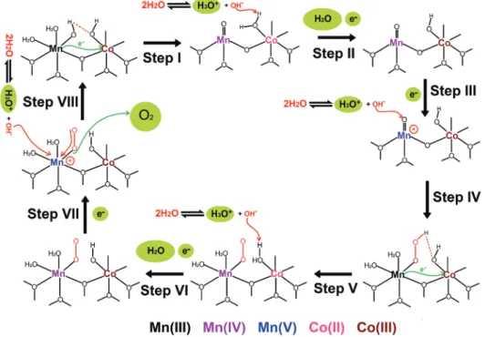
The improved overpotential and faster kinetics of the water oxidation reaction could be related to an electronic synergy between Mn(III) and Co(III) species as suggested in O2
reduc-tion process over a mixed manganese and cobalt oxide using in situ XANES (X-ray absorption near edge structure) data by Wang et al.[47,48] Accordingly, their reaction mechanism has
been modified and improved for OER, as shown in Figure 7. To start with, surface species were neutral with 3 lattice oxygens, 2 water, and a hydroxide group at the surface in both metal ions to have a charge balance at the surface. Metal oxo (MO) bond is also crucial for the OO bond formation in both commonly proposed two reaction mechanisms (nucleophilic acid-base, NAB, and radical coupling, RC, reactions) for both OER and O2 reduction reactions.[47–52] The NAB mechanism considers a
nucleophillic acid-base reaction between metal oxo surface spe-cies and hydroxide ion. The other mechanism considers a rad-ical coupling reaction between the MO species for the OO bond formation.[47–52]
We believe that a nucleophilic path is active over our elec-trode surface, see latter. The water oxidation half-reaction is initiated by an internal redox reaction between the neighboring Mn(III) and Co(III) surface species that leads to an oxidation of the Mn(III)OH and reduction of Co(III)OH sites by abstracting a hydrogen from the Mn(III)OH site. Since the
electronegativity of Mn is lower than Co (Millikan electronega-tivity of Mn is 3.72 eV and Co is 4.30 eV), the reaction in the first step produces a Co(II)OH2 and Mn(IV)O sites and
energeti-cally favored. Notice also that the (O)3Mn(IV)O surface
spe-cies has a C3V point group and a d3 electron configuration.
The low-lying partially filled e(dxz and dyz) orbitals of Mn(IV)
interact with the occupied oxygen e(2px and 2py) orbitals to
enhance the MnO π-bond strength, see Figure S15 (Sup-porting Information). Therefore, the electron donation from oxygen to Mn(IV) through π-interaction improves the electro-philic character of the oxo-oxygen. Notice also that odd electron configuration (d3) may also favor the RC mechanism.[52]
How-ever, further electrochemical oxidation of Mn4+ to Mn5+ makes
an even stronger electron donation form oxygen to manganese, due to a further increase in the electronegativity of Mn(V) side by oxidation that results a better π-interaction (better overlap-ping of the metal e(dxz, dyz) and oxygen e(px and py) orbitals
due to reduced electronegativity difference) between Mn and O orbitals and produces a highly electrophilic oxo-oxygen for the nucleophilic attack by a hydroxide ion. Moreover, the for-mation of Mn5+ creates a positively charged side (Mn(V)O+)
and attracts a hydroxide ion to its close vicinity for an effec-tive nucleophilic reaction. The evidence for the formation of Mn5+ (with a d2 configuration) species comes from the slow CV
measurements of the m-LiMn2O4 and m-LiMn2−xCoxO4
elec-trodes. The CVs at 2 mV s−1 scan rate displays a broad peak at
around 0.0 V, due to delithiation of m-LiMn2O4 as already being
previously discussed and another peak at around 0.30 V likely due to Mn4+/Mn5+ couple in an alkaline media, see Figure S16
(Supporting Information). Note also that the d2 configuration
favors the NAB path due to an amplified electrophilicity of the oxo-oxygen.[52]
Figure 7. Schematic representation of a likely reaction mechanism during OER and representative surface species over the m-LiMn2−xCoxO4
Therefore, in the second step, the Co(II)OH2 side is
elec-trochemically oxidized to produce the 1st electron and H+ ion
(as H3O+) of the 4 electrons and 4 H+ ions of the overall OER.
In this step, a hydroxide ion captures a hydrogen from the coor-dinated water (Co(II)OH2 side) to produce a water molecule
(or simply this could be an oxidative ligand exchange between a hydroxide ion in the solution and the coordinated water molecule). Note also that every hydroxide ion, used throughout the suggested mechanism, is a by-product of dissociation of
2 water molecules into a hydroxide (OH−) and hydronium
(H3O+) ions, therefore the mass and change balances of the
media are preserved throughout the process. The oxidative attack of the hydroxide in this step produces a H3O+ ion (from
the dissociation of water), H2O, and an electron, see Figure 7.
The third step of the process is another electrochemical
oxidation process, where the Mn(IV)O side is oxidized to Mn(V)O+ by releasing the 2nd electron. This step also
pro-duces a Mn(V)O+OH− side, where a hydroxide ion is in close
vicinity to the Mn(V)O+ side for an effective nucleophilic
attack to form a peroxide (Mn(III)OOH) specie, OO bond formation, in the fourth step. Moreover, the formation of MnOOH releases 2 electrons (due to reduction of oxo and hydroxy oxygens (O2−) to peroxide (O
22−)) to Mn(V) to reduce
it back to Mn(III) in step 4, see Figure 7. This step is the rate-determining step.[52] However, further detailed analysis of each
step needs to be investigated to determine the rate-determining step, which is critical for designing electrocatalysts. The fifth step proceeds by a reductive capture of peroxy-hydrogen by the neighboring Co(III)OH side and regeneration of the
Co(II)OH2 side and production of the Mn(IV)OO side
(this is also energetically favored if the electronegativity is con-sidered). Step 2 repeats in step 6 and produces Co(III)OH back with the 3rd electron, H3O+, and water. The last electron
of the cycle is electrochemically produced by the oxidation of
Mn(IV)OO to Mn(V)OO+/OH− in step 7. The last step
of the process is; two electrons oxidative release of O2 by an
attack of a hydroxide ion in the close vicinity of Mn(V)OO+
side and reduction of Mn(V) back to Mn(III)OH. This step also produces another H3O+ ion and the electrocatalytic-cycle
are complete, see Figure 7. The hydronium ions, which are needed in the other half-reaction (reduction of H+ to H
2) on
the cathode side are produced in steps 2, 4, 6, and 8 by the dissociation of water in the media, where the hydroxide ion is needed in the OER. The overall reaction of the proposed
8 steps uses 2 water molecules (8 H2O is used but 2 are
repro-duced in step 2 and 6 and 4 are reprorepro-duced as H3O+ in steps
2, 4, 6, and 8) to produce an O2 molecule, 4H+ ions (as H3O+),
and 4 electrons.
The reaction mechanism given above is suggested based on the electroneutrality principle, the electronegativity of the spe-cies, and experimental pieces of evidence. However, further mechanistic investigations are necessary to fully understand the reaction mechanism and the order of these steps and their rates. An appreciable electronegativity difference (0.58 eV) between Mn and Co improves the slow rate-determining step(s) (such as 1st and 4th steps, the formation of oxo side and nucleo-philic attack of hydroxide ion to form MnO and MnOOH sides) and also high affinity of water (as evidenced from density functional theory (DFT) calculations[48]) to Co side
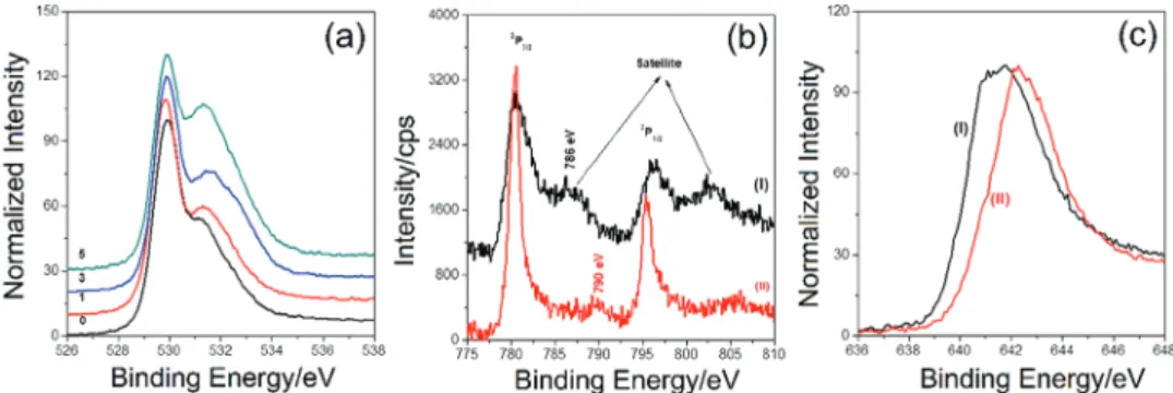
synergisti-cally amplify the OER reaction. Our XPS data also support this proposal, such that increasing Co by SILAR-AN increases the intensity of O 1s peak of coordinated/adsorbed water, hydroxide, and peroxy/oxo species on the pore-walls. Figure 8 shows a series of spectra before and after long-term CP experiments. The O 1s XPS spectra of the electrode after CV, chronoamper-ometry (CA), and long-run CP experiments display amplified peroxy or oxo peaks located at around 531.2 eV, see Figures S4 and 8a (Supporting Information). The Co 2p region loses the satellite peak at 786 eV, the main 2P
3/2 peak becomes sharper
with a weak satellite peak at around 790 eV, indicating the con-version of Co(II) to Co(III) species at the electrode surface, see Figure 8b. Similarly, the peak assigned to Mn(II) species disap-pears from the Mn 2p spectra upon long-term CP experiment, see Figure 8c. The spectral changes and quantitative analysis after series of CV, CA, and CP experiments show that the sur-face Mn(II) species are dissolved into the electrolyte media.[53]
Note also that the dissolution of Mn(II) into media has also been observed in lithium-ion batteries, constructed using LiMn2O4
anode, due to disproportionation reaction of Mn(III) sides to Mn(IV) and Mn(II) sides.[53] Therefore, the Mn/Co ratio over
the electrode surface drops to a level detected by EDX and XPS of the grind samples after CP experiments. The likely origin of the poor stability of m-LiMn2O4 electrodes could be the
dispro-portionation of Mn(III) to Mn(IV) and more soluble Mn(II) spe-cies (Mn(II) spespe-cies will form in place of Co(II) spespe-cies in the mechanism over the Mn-rich electrode surface) during OER. Furthermore, the suggested mechanism is consistent with the in situ attenuated total reflectance fourier transform infrared
Figure 8. XPS spectra of electrode surface: a) O 1s region of m-LiMn2O4-# (# is 0, 1, 3, and 5 as marked on the spectra) after 12 h CP experiment at
1 mA cm−2, b) Co 2p and c) Mn 2p (2P
(ATR-FTIR) evidence, collected from cobalt oxide,[54] iron
oxide,[55] and manganese oxide[56,57] electrodes during and after
OER process in various mechanistic studies in the literature. Presence of oxo-species (M(IV)O), peroxides (MOOH), and superoxide (O2−) has been identified by in situ studies during
the electrochemical process and later analysis of the used elec-trodes.[54–57] However, further characterizations and kinetic
studies, using surface sensitive in situ techniques and right (stable with a high surface area) electrodes, are required to fully understand the OER mechanism to design more efficient and stable electrocatalysts. Above proposed mechanism is an impor-tant attempt toward understanding OER over the metal oxides electrode surface and electronic synergic effects of two metals (Mn and Co) sides that collaboratively work together during OER on top surface of the m-LiMn2−xCoxO4-# electrodes.
3. Conclusion
MASA process is a one-pot synthesis method and applicable to synthesize mixed metal oxides (LiMn2−xCoxO4, where x was
varied from 0 to 0.5). A clear ethanol solution of all the ingredi-ents (lithium, manganese, and cobalt salts and surfactants) can be spin or drop-cast coated over FTO-coated glass or bared glass as a lyotropic liquid crystalline gel thin or thick film. Then, the gel films are calcined to obtain mesoporous LiMn2−xCoxO4 thin
electrodes and powder samples, respectively, with high surface area. The m-LiMn2−xCoxO4 electrodes can be further modified
by employing SILAR-AN method to obtain m-LiMn2−xCoxO4-#
electrodes, in which the BET surface area and pore size gradu-ally decrease with increasing the number of loading. The XPS, EDX, and XRD data collectively show that there is a Mn enrich-ment on the electrode outer surfaces in multiple SILAR-AN processes. Simply, the SILAR-AN method increases the cobalt content of the pore surface and the extracted Mn3O4 particles
accumulate over the top surface of the electrodes.
The m-LiMn2−xCoxO4 and m-LiMn2−xCoxO4-# electrodes show
good electrocatalytic performance OER in an alkaline media. The m-LiMn2−xCoxO4 electrodes (0 ≤ x ≤ 0.3) are unstable for
long-term OER, but the stability of the m-LiMn1.7Co0.3O4 electrode
can be improved by SILAR-AN modification. The modification reduces both Tafel slopes (as low as 46 mV dec−1) and
overpo-tential values (311 mV at 10 mA cm−2) of the electrodes. The
MASA method is not sufficient by itself to obtain such low Tafel slopes from the m-LiMn2−xCoxO4 electrodes, in which if the Co/
Mn ratio is kept the same as in the active m-LiMn1.6Co0.4O4-5
or m-LiMn1.7Co0.3O4-5 electrodes. It is likely that the surface Co
and Mn distribution over the electrode internal surface change with modification in a positive direction. Overall, the MASA and SILAR-AN methods need to be combined to produce stable and highly efficient m-LiMn2−xCoxO4-# thin film electrodes with
modest cobalt content.
The improved Tafel slope and low overpotential could be attributed to electronic synergy between the Mn and Co sites over the electrode surface. Higher electronegativity of Co over Mn is the driving force for the formation of Mn(IV)O sites
that can be further electrochemically oxidized to Mn(V)O+
sites for an effective nucleophilic attack of hydroxide for the for-mation of peroxide and later for the release of oxygen during
the electrocatalytic process. Both Co and Mn sites synergistically (electronic effect) work together to produce 4 electrons needed for the overall water splitting. Two of these electrons are elec-trochemically produced by the oxidation of Mn sites and two from the oxidation of Co(II) sites that form during overall OER. The likely origin of decomposition of m-LiMn2O4 electrode is
the disproportionation reaction of Mn(III) to Mn(IV) (active site) and Mn(II) (unstable site) that can be eliminated by incor-porating Co into the m-LiMn2−xCoxO4, where the
dispropor-tionation reaction produces rather stable and also active Co(II) sites in place of Mn(II). Note also that the Co(III)Co(III) sites (in place of Mn(III)Co(III)) are also stable and effective in the water oxidation process, however Mn(III)Mn(III) sites are unstable and inefficient. The suggested mechanism also corre-lates well with the observed instability of LiMn2O4 in lithium
ion batteries and OER process. The M(II) sites are particularly important in OER process and having a stable M(II) sites is a key for the OER process. The H+ ions are produced by the
dis-sociation of water to hydronium and hydroxide ions that are used in the multistep water oxidation process.
The electrocatalytic path of OER is a multistep and 4-elec-tron process that can be speeded up by appropriately designing materials with active sites and high surface area. Identifying the structure and composition of the active sites and/or spe-cies need further investigations by using in situ techniques to elucidate a more complete reaction mechanism for OER and to design more active and stable electrodes. Moreover, new inves-tigations for improving stability of Mn(III) sites, using 1st row transition metals with high natural abundance, less toxicity, and high electronegativity are on the way using MASA and/ or SILARAN to further improve the stability as well as perfor-mance of the electrodes.
4. Experimental Section
Synthesis of m-LiMn2−xCoxO4 Thin Films: The method described in
ref. [17] was used by only changing the composition of the initial clear solutions of the ingredients. Briefly, the clear homogeneous solutions were prepared by dissolving surfactants (P123 and CTAB) and salts (LiNO3 and [M(H2O)n](NO3)2, where M is Mn(II) and Co(II)) in 5 mL
ethanol, then they were acidified by adding 0.5 g concentrated nitric acid (70%) and stirred for overnight. The mole ratios of the ingredients in the solutions were 1:5:60 (P123:CTAB:salts). Only the Mn(II) and Co(II) mole ratios were varied from solution to solution by keeping the LiMn2−xCoxO4 stoichiometry (x was varied from 0 to 0.5) as a reference.
Table S3 (Supporting Information) tabulates the ingredient content of the solutions (solutions 1–6). Briefly, the solution 1 was prepared by dissolving first 0.173 g LiNO3 in 5 mL ethanol, then 0.230 g CTAB,
0.719 g P123, 0.550 g HNO3, and finally 1.255 g [Mn(H2O)4](NO3)2
(corresponds to 20:5:1:40, Li(I):CTAB:P123:Mn(II) mole ratio) were added to the above solution by stirring in an order with 5 min intervals and finally the overall solution was stirred overnight to obtain a clear solution for the preparation of mesoporous LiMn2O4. For the other
compositions (LiMn2−xCoxO4 (x is 0.1, 0.2, 0.3, 0.4, and 0.5)), solutions
2–6 were prepared only by reducing the amount Mn(II) salt and adding Co(II) salt in place in stoichiometric quantities. The amount of Mn(II) and Co(II) in the other 5 solutions (solutions 2–6) are 1.192 and 0.073 g, 1.130 and 0.145 g, 1.067 and 0.218 g, 1.004 and 0.291 g, 941 and 0.364 g, respectively. These solutions were spin or drop cast coated over FTO for the synthesis of electrodes or glass slides for bulk analysis (such as XRD pattern and N2 adsorption–desorption isotherms), respectively. The spin
or drop-cast coated films were directly calcined at 300 °C and annealed at higher temperatures for various purposes.
Modification of m-LiMn2−xCoxO4 Electrodes: SILAR method was
employed for the modification process. The LiMn2−xCoxO4 films were
coated with Co(II) species in three steps; in the 1st step, the film was dipped into a cobalt solution (1 m Co(II) solution, 14.547 g [Co(H2O)6]
(NO3)2 dissolved in 50 mL deionized water) for 20 s, then in the 2nd
step, it was removed from cobalt solution and hold over a paper towel (this ensures removing of any excess droplet over the film) and dipped into a deionized water bath for another 20 s, in the last step, step 2 was repeated using another deionize water bath to remove any undesired Co2+ species, accept a monolayer of Co2+ over the pore surface of the
film. After monolayer coating, the film was calcined at 300 °C for 1 h and annealed at higher temperatures (such as 400 and 500 °C) for electrochemical analysis. Above process were repeated # many times to prepare mesoporous LiMn2−xCoxO4-# (# is 1, 3, 5, and 7) electrodes.
Characterization: XRD patterns were collected using Rigaku Miniflex diffractometer, equipped with a Cu Kα (λ = 1.54 056 Å) X-rays source, operating at 30 kV 15 mA−1 and a Scintillator NaI(T1) detector with a Be
window and Pananalytical X’Pertpro Multipurpose X-ray diffractometer equipped with a Cu Kα (λ = 1.5405 Å) X-rays source, operating at 45 kV 40 mA−1. N
2 adsorption–desorption isotherms were collected
using Micromeritics Tristar 3000 automated gas adsorption analyzer in the range of 0.01–0.99 P/Po. Around 150 mg sample was dehydrated under a vacuum of 35–40 mtorr at 200 °C for 2 h prior to measurement. Saturated pressure measurements were repeated every 120 min during a 6–10 h measurement. The SEM images were recorded using field electron and ion (FEI) Quanta 200 F scanning electron microscope on aluminum sample holders. The XPS spectra were collected using Thermo Scientific K-alpha X-ray photoelectron spectrometer operating with Al Kα microfocused monochromatic source (1486.68 eV and 400 µm spot size) along with a flood gun for charge neutralization. The scraped powder samples from FTO electrodes were put on a copper tape for XPS analysis and the data were calibrated using C 1s peak. XPS spectra of the electrode surface were recorded by directly inserting the FTO-coated films into the spectrometer and making a contact between the electrode surface and spectrometer using a carbon type to avoid any surface charging. The electrochemical studies were carried out using m-LiMn2−xCoxO4-# (x is 0, 0.1, 0.2, 0.3, 0.4, and 0.5 and # is 0, 1, 3, 5,
and 7) coated FTO as working electrode, Pt wire as a counter electrode and Ag/AgCl (3.5 m KCl) electrode as a reference in a polypropylene cell with a 1.0 m KOH solution. The measurements were performed using a Gamry instrument (potentiostat-PC14G750). The measured potentials were corrected and reported to normal hydrogen electrode (NHE). Prior to electrochemical measurements, N2 gas was purged into
electrolyte solution for 15 min to get rid of any dissolved O2. CV, CA,
and CP measurements were performed subsequently for each electrode. CVs of the m-LiMn2−xCoxO4-# electrodes (working electrodes WEs) were
recorded in the potential range of −0.4–1 V (vs NHE) with a scan rate of 50 mV s−1. For each cyclic voltammogram, 3 cycles were collected, and
the 2nd cycle was presented. Positive feedback method was not applied during the measurements; therefore, the data were reported without IR compensation. In the CA measurements, a predetermined potential was applied to the WEs to collect the current data. During the experiment, the electrolyte solution was stirred using a magnetic stirrer. At each potential, the potential was applied for 5–10 min, depending on how fast a stable current level was reached; the last current data point is reported and used in further analysis. Tafel slopes were determined with the help of chronoamperometry experiments. The starting potential for the OER is determined by 1st CV and earlier potential value is adjusted as a starting point for the CA experiment. Then the adjusted potential was applied to the WE by CA for 5–10 min and the current value at the end of experiment was reported. This step was repeated every 20 mV increments and the current values were recorded for each applied potential. Then, the applied overpotential versus log(j) was plotted and the linear region is fitted to evaluate the Tafel slopes. From the fits, a Tafel equation (η = a + blog(j), where η is overpotential (V), j is the current density (A cm−2),
a is an empirical value, and b is the Tafel slope (V dec−1)) is obtained
to evaluate an estimated overpotentials at 1 and 10 mA cm−2 current
densities. CP experiments were carried at constant current densities of
1 and 10 mA cm−2 to evaluate overpotential values of the WEs. Potential
data were collected for 1–12 h, while stirring the electrolyte solution by a magnetic stirrer. The last data point was reported as a voltage value of the CP experiment. Then the potential required for OER (0.424 V vs NHE, from Nernst equation E = Eo−0.0592*pH, Eo is 1.229 V and pH is 13.6) is
subtracted from the collected data to evaluate the overpotential values.
Supporting Information
Supporting Information is available from the Wiley Online Library or from the author.
Acknowledgements
The authors thank to TÜBİTAK (under the Project No. 113Z730) for the financial support of this work. Ö.D. is a member of the Science Academy, Istanbul, Turkey.
Conflict of Interest
The authors declare no conflict of interest.
Keywords
lyotropic liquid crystals, molten salt assisted self-assembly, mesoporous thin films, SILAR, water oxidation electrocatalysts
Received: April 15, 2020 Revised: May 21, 2020 Published online: June 17, 2020
[1] R. D. L. Smith, M. S. Prevot, R. D. Fagan, S. Trudel, C. P. Berlinguette, J. Am. Chem. Soc. 2013, 135, 11580.
[2] L. Han, S. Dong, E. Wang, Adv. Mater. 2016, 28, 9266.
[3] M. G. Walter, E. L. Warren, J. R. McKones, S. W. Boettcher, Q. Mi, E. A. Santori, N. S. Lewis, Chem. Rev. 2010, 110, 6446.
[4] Y. Lee, S. Suntivich, K. J. May, E. E. Perry, Y. Shao-Horn, J. Phys. Chem. Lett. 2012, 3, 399.
[5] Y. Zhao, E. A. Hernandez-Pagan, N. M. Vargas-Barbosa, J. L. Dysart, T. E. Mallouk, J. Phys. Chem. Lett. 2011, 2, 402.
[6] C. C. L. McCrory, S. Jung, J. C. Peters, T. F. Jaramillo, J. Am. Chem. Soc. 2013, 135, 16977.
[7] S. Jung, C. C. L. McCrory, I. M. Ferrer, J. C. Peters, T. F. Jaramillo, J. Mater. Chem. A 2016, 4, 3068.
[8] T. Grewe, X. Deng, C. Weidenthaler, F. Schüth, H. Tüysüz, Chem. Mater. 2013, 25, 4926.
[9] Y. Wang, T. Zhou, K. Jiang, P. Da, Z. Peng, J. Tang, B. Kong, W. Cai, Z. Yang, C. Zheng, Adv. Energy Mater. 2014, 4, 1400696.
[10] L. Xu, Q. Jiang, Z. Xiao, X. Li, J. Hou, S. Wang, L. Dai, Angew. Chem., Int. Ed. 2016, 55, 5277.
[11] T. Y. Ma, S. Dai, M. Jaroniec, S. Z. Qiao, J. Am. Chem. Soc. 2014, 136, 13925.
[12] S. L. Brock, N. Duan, Z. R. Tian, O. Giraldo, H. Zhou, S. L. Suib, Chem. Mater. 1998, 10, 2619.
[13] D. M. Robinson, Y. B. Go, M. Greenblatt, G. C. Dismukes, J. Am. Chem. Soc. 2010, 132, 11467.
[14] C. Kuo, I. M. Mosa, A. S. Poyraz, S. Biswas, A. M. El-Sawy, W. Song, Z. Luo, S. Chen, J. F. Rusling, J. He, S. L. Suib, ACS Catal. 2015, 5, 1693. [15] C. Wei, Z. Feng, G. G. Scherer, J. Barber, Y. Shao-Hom, Z. J. Xu, Adv.
[16] L. Köhler, M. E. Abishami, V. Roddatis, J. Ceppert, M. Risch, ChemSusChem 2017, 10, 4479.
[17] F. M. Balci, I. Karakaya, E. P. Alsaç, M. Y. Yaman, G. Saat, F. Karadas, B. Ülgüt, Ö. Dag, J. Mater. Chem. A 2018, 6, 13925.
[18] Y. Guo, J. Tang, H. Qian, Z. Wang, Y. Yamauchi, Chem. Mater. 2017, 29, 5566.
[19] Y. Guo, J. Tang, Z. Wang, Y.-M. Kang, Y. Bando, Y. Yamauchi, Nano Energy 2018, 47, 494.
[20] Y. Guo, T. Park, J. W. Yi, J. Henzie, J. Kim, Z. Wang, B. Jiang, Y. Bando, Y. Sugahara, J. Tang, Y. Yamauchi, Adv. Mater. 2019, 31, 1807134.
[21] B. Tian, X. Liu, H. Yang, S. Xie, C. Yu, B. Tu, D. Zhao, Adv. Mater.
2003, 15, 1370.
[22] A. Rumpleker, F. Kietz, E. Salabas, F. Schüth, Chem. Mater. 2007, 19, 485.
[23] C. J. Brinker, Y. Lu, A. Sellinger, H. Fan, Adv. Mater. 1999, 11, 579. [24] G. Saat, F. M. Balcı, E. P. Alsaç, F. Karadas, Ö. Dag, Small 2018, 14,
1701913.
[25] A. Amirzhanova, I. Karakaya, C. B. Uzundal, G. Karaoğlu, F. Karadas, B. Ülgüt, Ö. Dag, J. Mater. Chem. A 2019, 7, 22012. [26] C. Karakaya, Y. Türker, C. Albayrak, Ö. Dag, Chem. Mater. 2011, 23,
3062.
[27] C. Karakaya, Y. Türker, Ö. Dag, Adv. Funct. Mater. 2013, 23, 4002. [28] C. Avcı, A. Aydınlı, Z. Tuna, Z. Yavuz, Y. Yamauchi, N. Suzuki,
Ö. Dag, Chem. Mater. 2014, 26, 6050.
[29] Ö. Çelik, Ö. Dag, Angew. Chem., Int. Ed. 2001, 40, 3800. [30] C. Albayrak, N. Özkan, Ö. Dag, Langmuir 2011, 27, 870. [31] C. Albayrak, A. Cihaner, Ö. Dag, Chem. – Eur. J. 2012, 18, 4190. [32] H. M. Pathan, C. D. Lokhande, Bull. Mater. Sci. 2004, 27, 85. [33] M. A. Becker, J. G. Radich, B. A. Bunker, P. V. Kamat, J. Phys. Chem.
Lett. 2014, 5, 1575.
[34] T. Kanniainen, S. Lindroos, T. Prohaska, G. Friedbacher, M. Leskela, M. Grasserbauer, L. Ninisto, J. Mater. Chem. 1995, 5, 985.
[35] Z. Su, K. Sun, Z. Han, F. Liu, Y. Lai, J. Li, Y. Liu, J. Mater. Chem.
2012, 22, 16346.
[36] I. Uzunok, J. Kim, T. O. Çolak, D. S. Kim, H. Kim, M. Kim, Y. Yamauchi, Ö. Dag, ChemPlusChem 2019, 84, 1544.
[37] D. Tang, L. Ben, Y. Sun, B. Chen, Z. Yang, L. Gu, J. Mater. Chem. A
2014, 2, 14519.
[38] H. W. Nesbitt, D. Banerjee, Am. Mineral. 1998, 83, 305. [39] S. Jeong, S. Park, J. Cho, Adv. Energy Mater. 2011, 1, 368.
[40] J. C. Dupin, D. Gonbeau, P. Vinatier, A. Levasseur, Phys. Chem. Chem. Phys. 2000, 2, 1319.
[41] M. C. Biesinger, B. P. Payne, A. P. Grosvenor, L. W. M. Lau, A. R. Gerson, R. St. C. Smart, Appl. Surf. Sci. 2011, 257, 2717. [42] M. M. Thackeray, P. J. Jonson, L. A. De Picciotto, W. I. F. David,
P. J. Bruce, J. B. Goodenough, Mater. Res. Bull. 1984, 19, 179. [43] N. Li, C. J. Patrissi, G. Che, C. R. Martin, J. Electrochem. Soc. 2000,
147, 2044.
[44] E. Hosono, T. Kudo, I. Honma, H. Matsuda, H. Zhou, Nano Lett.
2009, 9, 1045.
[45] G. J. Wang, Q. T. Qu, B. Wang, Y. Shi, S. Tian, Y. P. Wu, R. Holze, Electrochim. Acta 2009, 54, 1199.
[46] F. Cheng, Y. Su, J. Liang, Z. Tao, J. Chen, Chem. Mater. 2010, 22, 898.
[47] Y. Yang, Y. Wang, Y. Xiong, X. Huang, L. Shen, R. Huang, H. Wang, J. P. Pastore, S. H. Yu, L. Xiao, J. D. Brock, L. Zhuang, H. D. Abruna, J. Am. Chem. Soc. 2019, 141, 1463.
[48] Y. Wang, Y. Yang, S. Jia, X. Wang, K. Lyu, Y. Peng, H. Zheng, X. Wei, H. Ren, L. Xiao, J. Wang, D. A. Muller, H. D. Abruna, B. J. Wang, J. Lu, L. Zhuang, Nat. Commun. 2019, 10, 1506.
[49] J. P. McEvoy, G. W. Brudvig, Chem. Rev. 2006, 106, 4455.
[50] D. W. Shaffer, Y. Xie, J. J. Concepcion, Chem. Soc. Rev. 2017, 46, 6170. [51] W. Ruttinger, G. C. Dismukes, Chem. Rev. 1997, 97, 1.
[52] T. A. Betley, Q. Wu, T. V. Voorhis, D. G. Nocera, Inorg. Chem. 2008, 47, 1849.
[53] J. B. Goodenough, Y. Kim, Chem. Mater. 2010, 22, 587. [54] M. Zhang, M. Respinis, H. Frei, Nat. Chem. 2014, 6, 362. [55] O. Zandi, T. W. Hamann, Nat. Chem. 2016, 8, 778.
[56] Z. N. Zahran, E. A. Mohamed, Y. Naruta, ACS Catal. 2016, 6, 4470. [57] K. Jin, H. Seo, T. Hayaski, M. Balamurugan, D. Jeong, Y. K. Go,
J. S. Hong, K. H. Cho, H. Kakizaki, N. Bonnet-Mercier, M. G. Kim, S. H. Kim, R. Nakamura, K. T. Nam, J. Am. Chem. Soc. 2017, 139, 2277.