MEASUREMENT OF SENSITIVITY OF DIFFERENT
WAVE MODES TO SUBSURFACE DEFECTS
Abdullah Atalar
t, Hayrettin Koymen, a n d Ozuz Yemigciler
Middle East Technical University, Ankara, T U R K E Y
t Bilkent University, Ankara T U R K E Y
ABSTRACT
Excitation of acoustic wave modes in a layered solid is investigated when the solid is immersed in a liquid. This is done by computing the reflection coefficient of acoustic plane waves at the liquid-layered-solid interface. Then, a method to evaluate the sensitivity of various modes supported in the layered structure t o subsurface defects is introduced. T h e method involves insonification of the layered structure with a con- ical wave whose axis coincides with the defect. Since all the rays in the conical wavefront hit the planar interface at the same angle, it is possible t o excite a single kind of mode in the layer. By adjusting the angle of inclination of the cone, it is possible t o excite the modes selec- tively. Since the conical waves converge t o a line focus at the cone axis, the excited mode will focus on the defect. By recording the reflected signal amplitude as the cone angle is varied, a curve is obtained from which it is possible to conclude the sensitivity of various modes t o the subsurface flaw. T h e results of such measurements indicated that the generalized Lamb wave modes are more sensitive to subsurface defects than the Rayleigh waves. An imaging system which makes use of fo- cused Lamb waves was built and the system produced images of very small subsurface defects.
I. INTRODUCTION
Structures having layers made u p of different materials are frequently used in industry. Adhesion properties of layers on the substrate is
of critical importance. Observation of the interface between layers through possibly opaque materials is very difficult. Use of bulk acoustic waves for the purpose of imaging flaws and discontinuities is compli- cated by the presence of multiple internal reflections, the occurrence of surface waves, and the transformation of longitudinal waves into shear waves. Although pulse-echo methods, in conjunction with holo- graphic imaging, may be used to reject multiply reflected signals and thus simplify the interpretation, the obtained images are in general very difficult t o interpret even for the simple shaped solids. On the other hand, use of surface acoustic waves for the imaging of such structures is limited to a region very close to the surface. Moreover, surface acoustic waves are rather insensitive t o the inhomogeneities at interfaces several wavelengths below the surface. Layered structures support additional types of acoustic waves apart from bulk and surface waves. When the structure is immersed in a liquid, these modes can be excited by waves generated in the liquid, incident at a critical angle.
In this paper, (i) we investigate theoretically the excitation of various layer modes in the solid structure by the bulk waves in the immersion liquid; (ii) we introduce a method t o evaluate the reflection sensitivity of various modes t o subsurface defects; and (iii) a method of imaging subsurface interfaces by one of the sensitive modes.
0090-5607/88/0000-0771 $1
.OO 0
1988 IEEE
1
0 0.1 0.2 0.3 0 . L 0 . 5 0.6 0 7 0 8
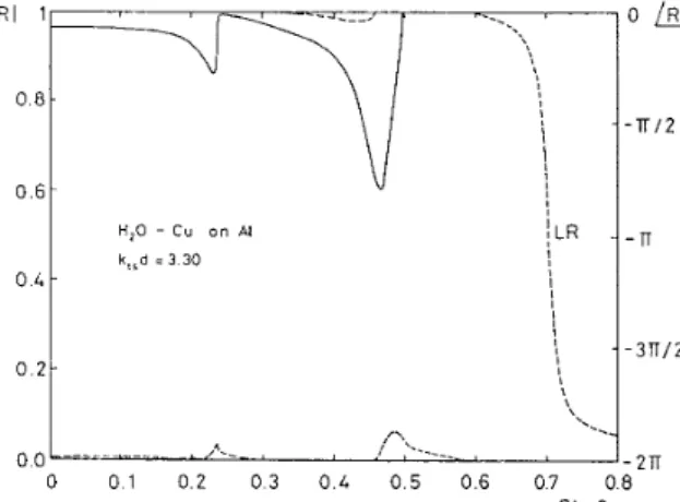
Figure 1: Plane wave reflection coefficient for a 0.8 mm copper layer on a n aluminum substrate at 2 MHz ( k t , d = 3 . 3 0 ) .
Sin 8
11.
EXCITATION
OF
LAYER
MODES
I t is well known that the Rayleigh waves can be excited on the planar surface of a solid material immersed in a liquid by bulk waves incident on the surface from the liquid side, provided that the angle of incidence is at the Rayleigh critical angle [l]. This forms the basis of the wedge transducers [ 2 , 3 , 4 ] . The excitation of a Rayleigh wave on the surface
exhibits itself as a phase transition at the critical angle in the plane wave reflection coefficient as a function of incidence angle [ 5 ] .
Waves excited in a layered soiid structure will be either bulk waves or leaky interface waves. The leaky waves can be in the form of leaky Rayleigh waves or layer waves such as generalized Lamb waves [ 6 ] . T h e
reflection coefficient a t the liquid-layered-solid interface exhibits phase transitions corresponding to these modes. The angular positions of the phase transitions can be used to predict the incidence angle of the bulk wave in the liquid for efficiently exciting the respective layer modes. An analytic expression for the reflection coefficient at the liquid-layered- solid interface for a single layer is given in the literature [ 7 , 8 ] . We
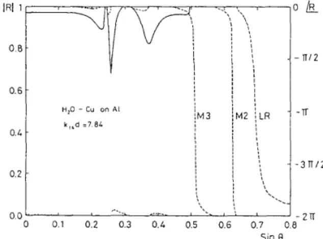
computed this reflection coefficient for some layered structures. Fig. 1 shows the reflection coefficient amplitude and phase between water and a copper layer on a n aluminum substrate for kl,d=3.30, where k,, is the shear wavenumber of the substrate and d is the layer thickness. As seen in the figure, for a thin layer of copper there exists a single transition in the phase which corresponds to a leaky Rayleigh-like (LR) wave. For this particular case, this mode is slower than the Rayleigh wave on the free copper surface. As the layer thickness is increased (see Fig. 2), a second mode (M2) appears as indicated by the second phase transition in the reflection coefficient. This mode is a generalized
I R I
1 0.8 0.6 0.L 0.2 0 0 I I I H,O - C u on At 2TI 0 0 0 0 1 0 2 0 3 0 4 0 5 0 6 0 7 1 Sine
k
Ir12 TI 3TiI2 2TTFigure 2: Plane wave reflection coefficient for a 1.2 m m copper layer on a n aluminum substrate a t 2 MHz (k,,d=4.95).
Lamb wave which is leaky due to the presence of the fluid. A second generalized Lamb wave mode (M3) emerges when the layer thickness is further increased as depicted in Fig. 3. The existence of various
modes and their excitation angles are compactly presented in Fig. 4
as a function of the kd.d. This figure is actually a different way of
displaying dispersion relation
[Q].
Note that, it depicts only the leaky waves, it does not show bulk waves which may also be excited. LR mode has a wave speed close t o that of Rayleigh wave in the substrate material when the layer is very thin. As the layer thickness is increased the phase velocity decreases rapidly, and it becomes smaller than the phase velocity of the Rayleigh wave in the layer material. As the layerthickness is further increased, the wave gets faster and it approaches t o the speed of the Rayleigh wave in the layer material. M2 mode exists only for layer thicknesses above a certain critical value. At the cutoff point the wave speed is equal t o that of the shear wave in the substrate material, and for a thicker layer i t approaches t o the shear wave speed of the layer material. 1113 and higher modes have a very similar behavior t o M2 mode except that they exist for even thicker layer widths.
It was shown that only a single mode (LR) can exist when the layer material has a higher transverse speed than that of the substrate [lo]. Hence, an aluminum layer on a copper substrate would not support generalized Lamb wave modes.
111. SENSITIVITY MEASUREMENT OF
MODES T O SUBSURFACE DEFECTS
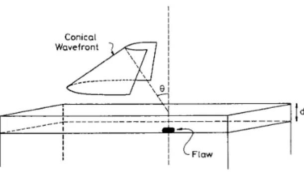
The defects in a multilayered structure can exist in the layer, on the interface or under the interface. Our aim is t o determine the most sen- sitive wave mode for detection of these defects. As shown in Fig. 5, themethod proposed here involves first the generation of a conical wave with the cone axis perpendicular to the layered surface under exami- nation. The technique of obtaining conical wavefronts was described elsewhere [ l l ] . Such a conical wave has the property that the conical nature will be preserved upon transmission through any planar interface perpendicular t o the cone axis, regardless of the mode into which it is converted. This is due to the fact that all the rays in the wavefront have the same angle of incidence with respect t o the planar interface. On the contrary, spherical waves will not preserve their shape upon transmis- sion through planar boundaries. T h e excited conical bulk (longitudinal
or shear) waves form a line focus with a linear phase in the solid ma-
IRI
1 0.8 0.6 0. L 0.2P
77/2Tr
37712Lerlal, V U L I V I IllVSL Case> Lllay U0 I l V L geL exclLeu W L L l l a lllgll elllclellcy because of the impedance mismatch between the immersion liquid and the material. For some angles i t may be possible t o excite shear waves with a reasonable efficiency. On the other hand, leaky layer waves are excited with a high efficiency. Since the excited Lamb waves propagate parallel to the interface, they form a cylindrical wave converging t o a line focus. T h e focal line will be normal to the surface and its height will he limited by the layer width. For minimum loss in a pulse-echo arrangement, the lateral size of the conical wave must be proportional t o the Schoch displacement for the particular mode [ll].
T h e measurement technique can be implemented by aligning the fo- cal line of the conical wave with the subsurface defect (Fig. 5). The
reflected waves from the defect leak back into the liquid medium and subsequently detected. T h e detected signal amplitude is recorded as
the angle of conical wave is varied. When the received signal amplitude is plotted as a function of incidence angle, the resulting curve, which we call V(0), can be used to deduce the relative sensitivities of the
excited modes and the most sensitive excitation angle for detection of the particular defect.
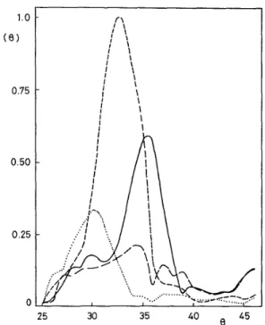
Fig. 6 depicts measurement results for V(0) for a copper layer on an
aluminum substrate with an artificial flaw a t the interface between the copper and the aluminum. The flaw is 3 mm diameter and 1 mm
deep indentation in the aluminum substrate hidden by the 1.12 mm thick copper layer. Measurements are repeated at different frequencies which corresponds to ktsd values of 3.70, 4.16, 4.62 and 5.08. The
curves are normalized with respect to the response of the transducer a t the measurement frequencies. As the k,,d value is increased the peak
of the curves shift toward higher 0 values. Comparison of the curves
with Fig. 4 shows that the peaks are associated with the M2 mode
(leaky generalized Lamb wave). T h e peak related t o the Rayleigh-like wave around 44 degrees is not significant. The Schoch displacement
parameter for the Lamb wave mode is considerably higher than that for the Rayleigh-like mode (101. In the experiment, the lateral size of the conical wave was optimized for LR mode. Therefore, there would be more conversion loss for M2 mode excitation. Inspite of this fact, the M2 mode peak is much higher than the LR mode peak. This shows that there is very little reflection of Rayleigh-like wave from the defect. Notice also that the magnitude of the peak is considerably different for different kt,d values. This may be due to varying conversion efficiency
of conical wedge a t different frequencies, or due to varying reflection coefficient at the defect.
T h e correspondence between the V(0) curves and Fig. 4 is good but
50
I
I
Figure 4: Excitation angle of various modes from the liquid side as
a function of copper layer thickness-wavenumber product on an alu- minum substrate
not perfect. T h e small disagreement may be a consequence of the fact that the conical wave in the experiment is not ideal. T h e angle that the rays of the conical wave makes with the normal t o the surface has an angular variance of 4 degrees. This causes an integration effect within
the angular coverage of the beam. An examination of Fig. 1 shows that in addition to leaky waves it is possible t o excite shear waves with high efficiency a t angles close t o 30 degrees. Moreover, these waves differ
in phase from the Lamb waves by 180 degrees upon reflection. Hence,
if shear waves and Lamb waves are excited simultaneously, then the reflected waves will add destructively on the transducer surface. The V ( 8 ) curves include the consequences of such interference. Supporting this fact, in some cases pulsed measurements revealed two pulses which interfered with each other visible on the oscilloscope screen. To get a better delineation of various modes in V ( 8 ) curves, one needs a more accurate conical wave.
As the particular layer mode impinges on the defect which can be of any shape or character, a very complicated reflection process takes place [la]
and a multitude of modes will be reflected. T h e reflected modes could be longitudinal waves, shear waves, Rayleigh waves or Lamb waves. In the proposed measurement technique, the output signal amplitude is proportional only t o the amplitude of the reflected interface mode which was originally excited. The other reflected modes will not contribute anything significant t o the output signal, because they will not be able to form the original conical wave in the liquid medium.
IV. IMAGING USING FOCUSED LAMB
WAVES
As seen in the previous section, generalized Lamb waves exist under
certain conditions. For their presence, the shear wave speed of the layer material must be less than that of the substrate material and the layer must be thick enough. If they exist, they provide potentially higher sensitivity t o defects at the interfaces compared t o the Rayleigh wave. This fact can be exploited to obtain images of subsurface defects with high sensitivity.
An imaging system based on mechanical scanning [13] was built which
scans the surface with focused Lamb waves. A phantom was machined t o test the potential of Lamb waves t o subsurface defects. Indentations
~ to simulate flaws ~ of depth 0.6 mm, and 1.0 mm were milled on
an aluminum surface on which a copper layer of 1.12 mm thickness was
epoxy-bonded to hide these artificially induced flaws. This phantom
I
j
LF'awI
Figure 5: Geometry for V ( 8 ) measurement
was imaged with an incidence angle of 34 degrees (2 MHz) with a kt,d
of 4.62 (Fig. 7). In the image higher signal levels are mapped to darker pixels. T h e excited mode corresponds t o a generalized Lamb wave in the copper layer. This Lamb wave image clearly shows all the hidden indentations on the aluminum surface. T h e received signal level for 1 mm deep indentation is higher than that for the 0.6 m m deep, which
is an expected result. But, the signal obtained from a 1.5 mm deep
indentation (not seen in the image) is lower than that from the 1 mm
deep. In addition t o the indentations, there is a significant structure in the image which is probably due t o the imperfections in the epoxy- bond. If the angle of incidence of the conical wave is adjusted around
30 degrees or lower to excite shear waves, the resulting image shows
only the indentations, but not the additional structure. Therefore, the image shown in Fig. 7 is truly an interface image. It shows the inhomogeneities in the interface between the layer and substrate and in the layer itself.
Experimentation with other phantoms indicated that the sensitivity of the system is very good. It was possible to detect 0.1 mm deep indentations below 1.6 mm thick copper layer with a high signal-to-
noise ratio. This is a good result since the wavelength of shear waves in the substrate is about 1.5 mm.
We must point out that the shapes of detected structures in the image are more related to the response of the imaging system than the defects themselves. T h e system has a good resolution in horizontal direction, but it has a poor vertical resolution. T h a t is why the circular indenta- tions show up as elongated ellipses in the image. T h e vertical resolution can also be improved by proper signal processing and making use of time of flight data [14]. T h e signal to noise ratio of the received signal
is very good, although no optimization [ l l ] of conical wave size has
been done. I t is possible t o increase the signal level considerably after the optimization. Finally, we must add that the indentations in this phantom are not visible under an X-ray imaging system.
CONCLUSIONS
We have introduced a method to selectively measure the sensitivity of excited modes t o small defects in a layered structure. This method results in a curve called V ( 8 ) which has a morphology depending on the geometrical and elastic properties of the layered structure and of the defect. From this curve one can ascertain the most sensitive mode and hence the most suitable excitation angle for the particular type of defect.
V ( 8 ) curves are affected by several factors: Conversion efficiency of bulk waves to the excited mode, reflection coefficient of the particular interface mode from the defect, the shape of the defect. V ( 8 ) curves provide the sensitivity information in the most appropriate combina- tion of the above factors. The maximum response point on the curves
1.0
v
(8)
0.75 0.50 0.25 045
e
25 30 35Figure 6: Measured V ( 0 ) curves for a 1.12 mm thick copper layer on aluminum substrate at kt.d=3.70 (dotted), 4.16 (dashed), 4.62 (solid) and 5.08 (long dashed). Defect is a 3 mm diameter and 1 mm deep indentation in the substrate.
will indicate the most sensitive incidence angle for waves in the liq- uid medium. This information can be used t o devise special excitation geometries, e.g. for acoustic microscopes.
T h e interface between a copper layer on a n aluminum substrate is stud- ied and V ( 0 ) curves are measured for artificially induced defects. Mea-
surements indicate that the Lamb wave modes are more sensitive than the Rayleigh-like mode. Using the Lamb wave modes images of the in- terface are produced. T h e inhomogeneities a t the interface are detected with a high sensitivity and with a diffraction limited resolution. Improving the conical wave and optimizing its size for the Lamb wave modes will help produce better images because of better selectivity among various modes and higher signal to noise ratio.
References
[l] K.L. Bertoni and T . Tamir, “Unified theory of Rayleigh angle phenomena for acoustic beams a t liquid--solid interfaces”, Appl. Phys., ~01.2, pp.157-172, 1973.
[2] H.L. Bertoni and T . Tamir, “Characteristics of wedge transducers for acoustic surface waves”, IEEE Zkans Sonics Ultmson., vol. 22, pp. 415-420, 1975.
[3] H.L. Bertoni, “Coupling layers for efficient wedge transducers”,
IEEE Dans. Sonics Ultrason., vol. 22, pp. 421-430, 1975.
[4]
J.
Fraser, P.T. Khuri-Yakub and G.S. Kino, “The design of efficient broadband wedge transducers,” Appl. Phys. Lett., vol. 32, pp. 698- 700, 1978.[5] L.M. Brekovskikh, Waves in Layered Media, (Academic Press, New York, 1960). 1.12 mm. Copper
I
I
J
1 mm. .6mmlL
I
Aluminumt
ii
Figure 7: Lamb wave image of artificially induced flaws a t t h e interface between a 1.12 mm thick copper layer and an aluminum substrate a t 2 MHz.
[6] D.E. Chimenti, A.H. Nayfeh and D.L. Butler, “Leaky Rayleigh waves on a layered halfspace,” J. Appl. Phys., vol. 53, pp. 170- 176, 1982.
[7] D.L. Folds and C.D. Loggins, “Transmission and reflection of ul- trasonic waves in layered media,” J. Acoust. Soc. Am., vol. 62, pp. 1102-1109, 1977.
[8] D.B. Bogy and S.M. Gracewski, “Reflection coefficient for plane waves in a fluid incident on a layered elastic half-space,” J . Appl.
Mech., vol. 50, pp. 405-414, 1983.
[9] G.W. Farnell and E.L. Adler, “Elastic Wave propagation in thin layers,” in Physical Acoustics, edited by W.P. Mason and R.N. Thurston, (Academic, New York, 1972) vol. IX, pp. 35-127, [lo] A.H. Nayfeh, and D.E. Chimenti, “Reflection of finite acoustic
beams from loaded and stiffened half-spaces,” J. Acoust. Soc. Am., vol. 75, pp. 1360-1368, 1984.
[ l l ] A. Atalar and H. Koymen, “Use of a conical axicon as a surface acoustic wave focusing device”, IEEE Trans. Ultrason. Ferro. and
Freq. Cont., vol. 34
,
pp. 53-63, 1987.[12] F.C. Cuozzo, E.L. Cambiaggio, J-P Damiano, and E. Rivier, “In- fluence of elastic properties on Rayleigh wave scattering by normal discontinuities,” IEEE Trans. Sonics Ultmson., vol. 24, pp. 280- 289, 1977.
[13] B. Koymen, A. Atalar, T . Ciloglu, M. Onder, Cetin Uzel and
H. Yavuz, “Imaging flaws close t o surface using focused surface acoustic waves” in Proc. IEEE Ultmsonics Symposium, pp. 755- 758, 1986.
[14] S. Ayter, “Focusing surface waves using conical transducers,” in Proc. of 1987 IEEE Ultmson. Symp., pp. 301-304, 1987.
774
-
1988 ULTRASONICS SYMPOSIUM
-___ ~~