T.C.
ISTANBUL AYDIN UNIVERSITY INSTITUTE OF GRADUATE STUDIES
HARMONIC CURRENTS IN PHOTOVOLTAIC SYSTEM
YÜKSEK LİSANS TEZİ
Raja Muhammad Junaid Abbas
Department of Electrical & Electronic Engineering Electrical and Electronics Engineering Program
T.C.
ISTANBUL AYDIN UNIVERSITY INSTITUTE OF GRADUATE STUDIES
HARMONIC CURRENTS IN PHOTOVOLTAIC SYSTEM
YÜKSEK LİSANS TEZİ
Raja Muhammad Junaid Abbas (Y1813.300028)
Department of Electrical & Electronic Engineering Electrical and Electronics Engineering Program
Thesis Advisor: Prof. Dr Murtaza FARSADI
DECLARATION
I hereby declare with respect that the study “Harmonıc Currents In Photovoltaıc System”, which I submitted as a Master thesis, is written without any assistance in violation of scientific ethics and traditions in all the processes from the Project phase to the conclusion of the thesis and that the works I have benefited are from those shown in the Bibliography. (.../.../20...)
FOREWORD
I would first like to thank ALLAH ALMIGHTY THE MOST GRACIOUS AND THE MOST MERCIFUL and then to my family who have always been supportive and encouraging, they raised me to become a good person and a positive member of society and were patient with me through good and better days and everything I have accomplished is because of their effort and i hope i can make them happy in return for all they have done for me. I would like to thank my thesis advisor Prof. Dr. Murtaza Farsadi of Electric and Electronic Engineering department at Istanbul Aydin University. The door to Prof. Murtaza Farsadi, office was always open whenever I ran into a trouble spot or had a question. He consistently allowed this paper to be my own work but steered me in the right the direction whenever he thought I needed it.
I would like to thank all my teachers for having great influence on me, I would like also to thank department of Electric and Electronic Engineering and also Istanbul Aydin University and its library for providing me with access to all the books and articles that I needed to finish this work.
August 2020 Raja Muhammad Junaid Abbas
TABLE OF CONTENT
Page
FOREWORD ... v
TABLE OF CONTENT ... vi
LIST OF FIGURES ... vii
LIST OF TABLES ... viii
ABSTRACT ... ix ÖZET ... x INTRODUCTION ... 1 1. 1.1 Definitions ... 2 1.2 Problem Statement ... 2
1.3 Total Harmonic Distortion (THD) ... 3
1.4 Literature review of inverters ... 3
1.5 Devices used for harmonic compensation ... 3
1.5.1 Passive harmonic compensation ... 4
1.5.2 Active harmonic compensation ... 5
CONFIGURATION OF THE SYSTEM ... 7
2. 2.1 Photovoltaic System History ... 7
2.1.1 Working of PV Cell. ... 8
2.1.2 Arrays, cells, modules. ... 9
2.2 Photovoltaic System Working. ... 9
2.2.1 Grid tie photovoltaic systems ... 11
2.3 Multilevel Inverters ... 12
2.3.1 Concept of multilevel inverters ... 12
2.3.2 Buck converters ... 14
2.3.3 Boost converter ... 15
2.3.4 Buck-Boost converter ... 16
2.3.5 Simple buck-boost design ... 17
2.3.6 Buck-boost characteristics ... 18 METHODOLOGY ... 19 3. 3.1 Mppt Operation ... 22 RESULTS ... 23 4. 4.1 IEE 519 ... 25 CONCLUSION ... 28 5. REFERENCES ... 29 RESUME ... 30
LIST OF FIGURES
Page
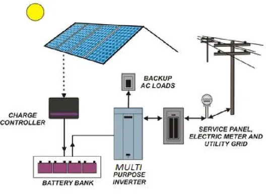
Figure 1.1: Photovoltaic System with Multi-purpose inverter. ... 2
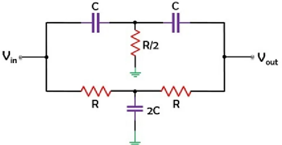
Figure 1.2: circuit of Passive Filter ... 5
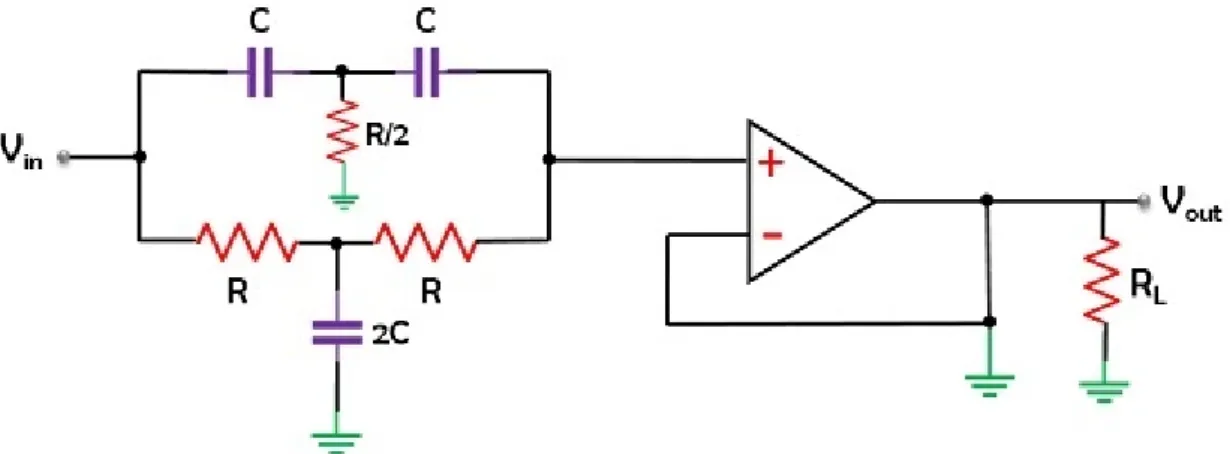
Figure 1.3: circuit of Active Filter ... 6
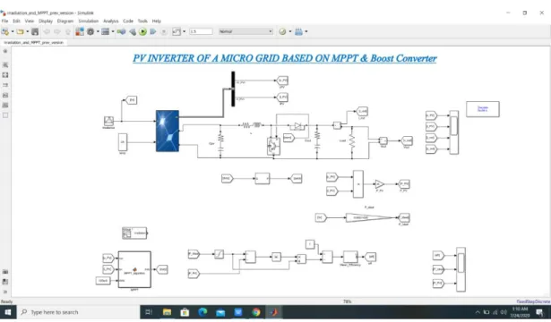
Figure 2.1: simulink model of the system ... 7
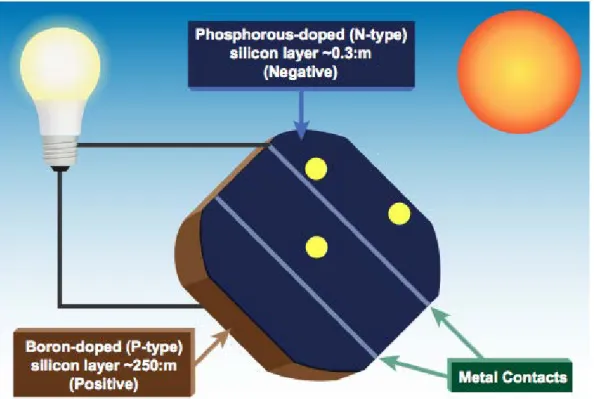
Figure 2.2: Basic Pave cell diagram ... 8
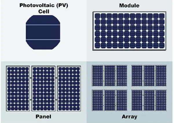
Figure 2.3: Structure pv cells, pv modules and pv arrays ... 9
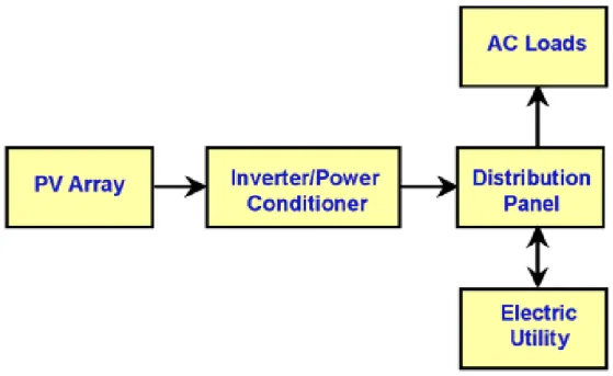
Figure 2.4: PV system working... 10
Figure 2.5: PV connected with grid ... 11
Figure 2.6: PV System with desired dc load ... 11
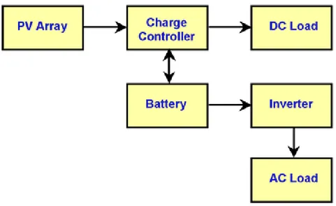
Figure 2.7: PV System with battery storage powering DC and AC loads ... 12
Figure 2.8: Output of Two Level Inverter... 13
Figure 2.9: A three-level waveform, -ve-level waveform and a seven-level multilevel waveform, switched at fundamental frequency ... 13
Figure 2.10: Simple Buck-Converter ... 14
Figure 2.11: Buck-Regulator Characteristics ... 14
Figure 2.12: Boost-Converter ... 15
Figure 2.13: Characteristics Boost-Converter ... 16
Figure 2.14: Buck Boost converter ... 17
Figure 2.15: Simple Buck-Boost Design ... 17
Figure 3.1:Reference harmonics current ... 19
Figure 3.2:Transformation matrix ... 20
Figure 3.3: proposed Simulink/MALTAB model ... 21
Figure 3.4: The Simulink Circuit of MPPT ... 22
Figure 4.1: Conversion Sinusoidal Wave ... 23
Figure 4.2: Current Wave... 23
Figure 4.3: Ideal Power, Output Power... 24
Figure 4.4: Current And Power of PV Module ... 24
LIST OF TABLES
Page Table 4.1: IEEE 519 Current Distortion Limits. ... 26
HARMONIC CURRENTS IN PHOTOVOLTAIC SYSTEM ABSTRACT
This idea is based on the adding of extra functions to the conventional photovoltaic systems, such as the harmonic current compensation of nonlinear loads and reactive power support. Though, it is significant to guarantee that photovoltaic inverters work below the rated current peak. Therefore, we will be designing an inverter during harmonic current compensation of nonlinear loads. We will be using a closed loop technique instead of open-loop technique. With this approach, the photovoltaic inverter will be able to perform partial harmonic current compensation, i.e., it will only be allowed to compensate harmonic currents within their maximum current capacity. By using the Park transformation, reference signals are converted first into 0 −α − β stationery frame, then into 0 − d − q rotating frame. It is a power control algorithm, (MPPT) that’s why we have used PI controller on active power and reactive power in-order to limit the current. By comparing and limiting both these powers, we get reference current which we feed to MPPT function. The simulation results provide improvements in the grid power quality at the same time as the inverter rated current capacity is respected.
Keywords: Photovoltaic Systems, Photovoltaic Inverter Control, Partial Harmonic
FOTOVOLTAİK SİSTEMDE HARMONİK AKIMLAR ÖZET
Bu fikir, doğrusal olmayan yüklerin harmonik akım kompanzasyonu ve reaktif güç desteği gibi geleneksel fotovoltaik sistemlere ekstra fonksiyonların eklenmesine dayanmaktadır. Yine de, fotovoltaik invertörlerin nominal akım tepe noktasının altında çalışmasını garanti etmek önemlidir. Bu nedenle, doğrusal olmayan yüklerin harmonik akım kompanzasyonu sırasında bir inverter tasarlayacağız. Açık döngü tekniği yerine kapalı döngü tekniği kullanacağız. Bu yaklaşımla, fotovoltaik invertör kısmi harmonik akım kompanzasyonu gerçekleştirebilecek, yani harmonik akımları yalnızca maksimum akım kapasiteleri dahilinde kompanze etmesine izin verilecektir. Park dönüşümü kullanılarak, referans sinyalleri önce 0 −α - β sabit çerçeveye, ardından 0 - d - q dönen çerçeveye dönüştürülür. Bu bir güç kontrol algoritmasıdır (MPPT), bu nedenle akımı sınırlamak için aktif güç ve reaktif güç üzerinde PI kontrolör kullandık. Bu iki gücü karşılaştırıp sınırlayarak, MPPT fonksiyonuna beslediğimiz referans akımı elde ederiz. Simülasyon sonuçları, inverterin nominal akım kapasitesine uyulduğu gibi aynı zamanda şebeke güç kalitesinde iyileştirmeler sağlar.
Anahtar Kelimeler: Fotovoltaik Sistemler, Fotovoltaik İnvertör Kontrolü, Kısmi
INTRODUCTION 1.
THE Photovoltaic framework which is connected to the Grid, inverter or converter take energy from the sun light via simply array or the PV array in to the AC Grid System. Their face an issue of irradiation of sunlight creates variations which becomes the cause of current margin which is not used in daily routine. This margin will become the reason to use multifunctional inverters, which can do not only the harmonic compensation but also the reactive power support and in this regard it will be beneficiary for the Grid [1][2][3]. Day by day the use of non-linear loads is increasing; these are also the reason of the harmonics getting in to the power system. Non-linear load devices are becoming the reason of power losses in the line [4]. For the current reason, identical to an active power filter the PV systems will have the grid interface. Numerous works also have preferred the reduction of the harmonics with the help of inverters caused by the non-linear devices. There are three major task is to be done for injecting the harmonics compensation in to the inverter. First task is to find the harmonic current of the nonlinear load. For this we have to use the reference frame transformation by using the Clark transformation and Park transformation. The second task is the synchronous frame which is controlled by PI controller. Integrator can reduce the steady state error of DC component. And the third task is to use of MPPT algorithm which can control the reactive and active power.
Figure 1.1: Photovoltaic System with Multi-purpose inverter. 1.1 Definitions
The word harmonics we can define it that the multiple of the voltage or it might be a current and their frequency which is produced by the non-linear load and it can be any device like computer, rectifier or it would be saturated magnetic device. These harmonics or the unwanted frequencies are the cause of the problems faced in the Power system. In power framework, harmonics becomes the reason of increasing temperature in the devices and conductors, torque pulsations in motors and misfiring in variable speed drives
1.2 Problem Statement
It is very important to have an idea about and have a firm knowledge about the limits of the harmonics to the supplier. This information awareness is good for both of the user and the supplier. Tolerance level should be at the recommended level because if the tolerance level should be increased than their will be definitely disturbance in the system and their will be no any surety for the smooth connection. And harmonics are also root mean cause of losses in the system.
1.3 Total Harmonic Distortion (THD)
We can define THD as “The ratio of the addition of the powers of all harmonic elements to the power of the fundamental frequency”.
1.4 Literature review of inverters
An inverter is an electric force gadget that we use to change over direct flow (DC) into exchanging flow. Some control circuit and switches, AC force can essentially be gotten at any voltage and recurrence. The inverter is absolutely inverse working to the rectifier. Rectifiers are utilized to change over rotating current (AC) to coordinate current (DC). Here we have numerous kinds of inverters available in the market. You can get the unadulterated sine wave transformed plan with code and adjusted sine wave with code. Generally utilized inverters are the accompanying:
• solar inverters
• Modified sine wave
• Pure sine wave
• Multilevel
• Grid tie inverters
• Resonant
• Synchronous inverters
• Square wave
1.5 Devices used for harmonic compensation
They are two type of harmonic compensator: passive filters and active filters. Passive filters are just combination of inductors and capacitors. We have many types of passive filters like LCL filter LC filter or L filter etc. The job of the filters is to create short circuit path for the unwanted harmonics to the ground so that they can vanish in the ground or create a high impedance path to the load so that they cannot travel to the load.
The job of the active filters are to forcefully shape the voltage or current so that the unwanted harmonics are minimized. Moreover, if the load demands harmonics from the grid the active filter will supply the harmonic demand not the grid. Because if we let the grid supply the harmonics demand of the load we pollute grid and power quality is compromised.
I will give example of a few techniques below.
1. Power factor correction circuit in diode bridge rectifiers 2. Using selective harmonic elimination in inverters.
3. High value of inductor can be used at the output of the inverter to eliminate the harmonics in current. Higher value of switching frequency also reduces the harmonics level.
4. A statcom (edit. or a unified power quality conditioner or a dynamic voltage restorer) can be connected to grid for the compensation of the harmonics.
1.5.1 Passive harmonic compensation
Passive harmonic compensation is done by the use of passive filters which is made up of the passive components it means that they are made up resistors, conductors and also made up of the inductors. Such elements are passive in nature which is not amplifying so due to this the out we get from this type of filters are always less than the input.
In such filters there is path created to the ground and or in other case if there is a inductor than the signal goes into the inductor. In grounded case the signal passes through the capacitor and than to the ground hence it will become a low pass filter. Such filter plays important role in the power System for the minimizing of the harmonics.
So as to structure a symphonious channel, data about the neighborhood power framework, including natural information, is required. Force framework data incorporates attributes, for example, the ostensible line-to-line voltage, average gear BIL for the framework voltage level, basic recurrence, framework setup, and impedance of framework segments. An away from of hardware area (for example indoor or open air), working limitations, gear current obligation cycle,
exchanging activity rates, natural information, (for example, encompassing temperature and wind stacking), symphonious estimations or producer consonant qualities, is essential to consider before beginning the channel configuration measure[5].
Figure 1.2: circuit of Passive Filter 1.5.2 Active harmonic compensation
Because of the expanding utilization of non-direct loads, for example, VFDs, harmonics are being brought into the force matrix which is adding to helpless force quality and prompts overheating of gear and aggravation issues. Dynamic Harmonic Filters are equal gadgets that are utilized to relieve harmnonics to the levels characterized by IEEE-519.HPS TruWave AHF uses high recurrence current sensors to ceaselessly screen the heap and consonant flows. By using exceptionally complex programming and an incredible DSP microcomputer, the framework can immediately infuse a restorative current from its IGBT based inverter to significantly decrease symphonious twisting. The restorative current is equivalent to however 180 degrees out of stage with the current symphonious flows to drop their impact. Active filters working on the identical principal as noise cancellation earphones only the harmonic currents and minimized the distortion.[6].
CONFIGURATION OF THE SYSTEM 2.
In this part we will talk about the system configuration and the major part of the system. We will start from the primary source of energy which we can get from the solar panels. After that we can use multifunctional inverter addition with the filterswhcich can convert the DC into the Ac and besides it can also inject harmonics for compensation or to cancel out the unwanted harmonics present in the system or generated by the non-linear loads. And we can use low pass filter for the cutt off frequencies, and we can use PI controller for the steady state error. MPPT algorithm along with PI controller is used for maximum Power tracking.
Figure 2.1: simulink model of the system
2.1 Photovoltaic System History
Photocell is used for the several years that was first created in the end 1950 and after that it can be later on in the end of the 1960 it is use in major things like the moving satellites. And after the mid of 1070s it is introduced to the public
and it is start manufacturing in the markets. And in 1980 it is used for the mini thing like small gadgets , calculators and it can also be used in the charging batteries and small watches are also working on this scenario. And After the 1990s it is used for the remotes areas. And now a days it is very important and very useful for the generation of the Electrical energy. Now a days there are big manufacturing companies of the solar modules. Now Dc inverters are introduced in the market which can directly working on this scenario because this is very cheap and economical. All countries which are advanced are using this technology for the generation of Electricity like tha USA, Japan and many European countries are also using this framework[7].
2.1.1 Working of PV Cell.
PV cell basically made up of silicon boules. The making of electric field is being done on the upper surface of the telephone where the relationship of two materials is made, which is called P-N crossing point. At the point when sunshine strikes on outter surface of the PV cell, this electrical field offers essentialness to light-breathed life into electrons, on account of this cycle the PV cell starts giving electrical imperativeness to the store which is related with it.
2.1.2 Arrays, cells, modules.
A photovoltaic cell is the most fundamental unit of a sun based PV framework - sun powered cells, which is made up of material named as the mono crystalline or the poly crystalline, it depends upon the quality of the cell, Mono-crystalline is cheaper than the poly crystalline. When the solar light strike to the solar cell than it generate the voltage.
Photovoltaic module is the combination of the solar cells which we work all together to achieve a large number of voltage, we can use modules according to our need.
When too many cells are gathered than it becomes a module, when the group of such modules connected or gathered than it becomes solar arrays. As you can see in the figure 6 you will clearly understand and difference between all these.
Figure 2.3: Structure pv cells, pv modules and pv arrays 2.2 Photovoltaic System Working.
Here we can talk about the Photovoltaic framework working, this system consist of three parts. Firs one is the getting energy part which is the solar array, which can directly from the sun, and the second part is the conversion and storing part,
here we can convert DC to Ac or if there are DC loads then no need of conversion they get the Dc directly from the Solar array or we can say it also the solar panel. And the last part is the load or the user. We can use for the separately for the individual for separate houses and we can also connect it to the AC grid according to our need [8]. Figure given below is the view of the working of the photovoltaic System.
Figure 2.4: PV system working
The figure 8 shows the flow chart of the PV system which connected to Electric utility and also with the load. First the solar irradiations strikes to the PV array and from there Energy is generated by the solar panels and then it goes into the inverter from here it will go the distribution channel from where one is connected is the Ac load and other is the Electric utility.
Figure 2.5: PV connected with grid 2.2.1 Grid tie photovoltaic systems
Here we can tell you about the Grid Tie System , in which we don’t need any inverter or any back up source. Our photovoltaic system consist of just the PV array which get the solar energy from the sun and then directly it is connected to the DC load which we have to use.
Figure 2.6: PV System with desired dc load
Here we discuss the Tie solar Network which is addition to the back up by mean of batteries, in this type of system , we have solar array from which we take solar energy and then from it goes to the charging controller which can charge the batteries and from charger controller direct Dc loads are connected but for the Ac load we need a inverter which is connected to the battery and all Ac load are connected to the inverter as shown in figure 10.
Figure 2.7: PV System with battery storage powering DC and AC loads 2.3 Multilevel Inverters
Multilevel inverters are electronic devices, which is fit for conveying wanted exchanging voltage level at the yield utilizing a few lowest level of the current. We already have two level inverter, which is used for the conversion of the Direct current into the Alternate current. But still we need multilevel inverters because of the many reasons.
2.3.1 Concept of multilevel inverters
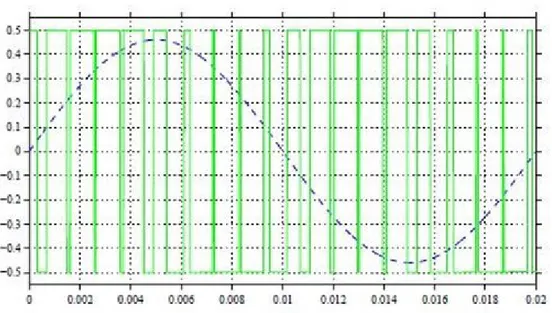
Initially we will consider a two level inverter from which we can get two different voltages, assume we have given the V into the input and after getting output from the inverter as the +V/2 and – v/2. To develop an AC voltage, these two as of late conveyed voltages are regularly traded. For changing over by and large PWM is used as showed up in the figure underneath, referred to wave is showed up in ran blue line. Notwithstanding the way that this strategy for making AC is successful anyway it has hardly any insufficiencies as it makes symphonious turns in the yield voltage and besides has a high dv/dt as compared to that of a stunned inverter.[3]
Figure 2.8: Output of Two Level Inverter
Multilevel inverter is the next form of the two level inverter which is more reliable and more safe for the devices, because we can get the more accurate wave from this type of inverter and more over it will be very helpful for the harmonic part of the system. It plays a vital role in that scenario. As much as waveform is going to smooth the voltage level will be also increased more over the controlled circuit and its all component will be increased with the higher level, the given below figure shows clearly wave form is going smoother and smoother as the level is going increased.
Figure 2.9: A three-level waveform, -ve-level waveform and a seven-level multilevel waveform, switched at fundamental frequency
2.3.2 Buck converters
Buck converter will not convert alternate current in to the direct current or topsy-turvy, it is actually a step down converter which can be used to step down the voltage of direct current and we know that when the voltage will be step down current will be stepped high, that’s the function of Buck converter.
Figure 2.10: Simple Buck-Converter
Figure 2.11: Buck-Regulator Characteristics 𝑽𝑶𝑼𝑻= 𝑽𝑰𝑵𝒕𝑶𝑵
𝑻 = 𝜹𝑽𝑰𝑵 , valid when 𝑽𝑰𝑵 > 𝑽𝑶𝑼𝑻 1.1 The transfer purpose buck-converter will be extended:
“For OFF: O/P Power = 𝑽𝑶𝑼𝑻𝒕𝑶𝑭𝑭” 1.3 Where, “𝑡𝑂𝐹𝐹 = 𝑇 − 𝑡𝑂𝑁” and “𝛿 =𝑡𝑂𝑁 𝑇 ” Substituting gives: “(𝑽𝑰𝑵− 𝑽𝑶𝑼𝑻)𝒕𝑶𝑵=𝑽𝑶𝑼𝑻(𝑻 − 𝒕𝑶𝑵) 1.4 𝑽𝑰𝑵𝒕𝑶𝑵 = 𝑽𝑶𝑼𝑻𝑻 𝑽𝑶𝑼𝑻= 𝑽𝑰𝑵(𝒕𝑶𝑵𝑻 ) 𝑽𝑶𝑼𝑻 𝑽𝑰𝑵 = 𝜹” 1.5
Equation 1.5 is the transfer function of Buck-Converter 2.3.3 Boost converter
DC-DC converters are otherwise called Choppers. Here we will examine the Step Up Chopper or Boost converter which builds the info DC voltage to a predefined DC yield voltage. An ordinary Boost converter is demonstrated as follows
Figure 2.13: Characteristics Boost-Converter “For I/P= 𝑉𝐼𝑁𝑡𝑂𝑁”
“For OFF O/P Power = (𝑉𝑂𝑈𝑇− 𝑉𝐼𝑁)𝑡𝑂𝐹𝐹”
"𝑽𝑽𝑶𝑼𝑻
𝑰𝑵 =
𝟏 𝟏 − 𝜹 "
Above equation is the transfer purpose for boost-converter. 2.3.4 Buck-Boost converter
Buck-Boost converter is special type of converter which we can use to get the greater at the output end. It does not convert the Direct current to Alternate current, it just boost the DC to up like a step up transformer but the difference is that there is only one inductor inside it.
Figure 2.14: Buck Boost converter 2.3.5 Simple buck-boost design
2.3.6 Buck-boost characteristics
Favorable position lies in the capacity to buck and lift dependent on the obligation cycle proportion. Pair these up with a criticism circle and you can hold a steady yield voltage with differing input voltages (high or low). The reasonable drawback (if there should be an occurrence of sources like sun oriented boards) is that they are intermittent current converters which implies that they draw current irregularly from the source which implies that the capacities of the source are restricted by the converter . The Cuk is better in this sense since it takes into consideration a current stream way all through its activity with lesser source ability restrictions
“𝑉𝑂𝑈𝑇 𝑉𝐼𝑁 =
−𝛿 1−𝛿”
METHODOLOGY 3.
The model that was simulated in Matlab is of MPPT controlled 50kw grid connected PV system.50kW PV group consists of 21 series and 11 parallel modules, and maximum power is 53KW at 1000W/m2 irradiance, while MPP voltage is 850V.To demonstrate the algorithm we have designed an inverter with one stage power converters and we will combine mppt and inverter control algorithm and for that we will use d-q theory or synchronous reference frame and shunt active filter. In order to improve the power quality of current supplied to utility network it is important to reduce current harmonics injection into power supply system which can be done with the help Shunt active filters. They acts as harmonic current source connected in parallel to distributing load. The harmonic wave of the system becomes reference for the inverter circuit.
Two main components of power control are given below Active power control
Reactive power control
For getting the reference harmonics current we first of all, achieve load current. Load current can be expressed by its two components fundamental current Il and the second one is the harmonic current IH. After them, with the help of a Low pass filter, we have to approximate cut-off frequencies, I1 is obtained from measured system load current using comparator, as shown in figure below. When we will compare the load current with the fundamental component than we will get the error which will be our reference harmonics signals
Now the reference frame transformation means to transform from a-b-c to d-q-0 axes. Which implies that coordinates from a three-phase a-b-c stationery coordinate system to the d-q-0 rotating coordinate system. Firstly we need to have transformation from a-b-c to alpha-beta coordinates is achieved and then to have the transformation to d-q-0 coordinates, with the help of Clarks Transformation and Parks transformation. Transformation matrix is given below
Figure 3.2:Transformation matrix
In synchronous reference frame we have used PI based controller having integrators which are employed to get rid of the steady state error of the DC components of reference signal’s 0 − d − q coordinates, in accordance to the 0 − d − q frame theory. After this, the current harmonics will be represented as DC components in their corresponding reference frame. Actually PI controller is doing the job of elimination of the steady state error, and that’s our aim here to achieve the controlled reference signal[10].
Since it is a power control algorithm, (MPPT) that’s why we have used PI controller on active power and reactive power in-order to limit the current. By comparing and limiting both of these powers, we obtain the reference current that feeds the MPPT function. To maintain the I/O linearity, the SSWM circuit is used to determine the VSC switching points, especially for applications with an active power filter. All modulation schemes are aimed at generating switched pulse trains in principle that have the same mean, mean in volts seconds, same as that of target reference waveform at any instant. There are many different ways to achieve switching instants, besides it can also manage the harmonics and it can reduce the harmonics contents. We can control the average value of the current and voltage which is fed to load by the use of switching, when it will be on and off at high speed it will control automatically. And one more thing power supplied to load will also be higher when switch is on.
Due to the over modulation we can get the low order hamonics which is done by the PWM Simulink Model and the method will be carrier based, and it will be done when M will be greater than 1 and also by the sampling process. And in the sampling the harmonics are cancelled because of the phase legs and all of the carrier combinations. There is a drawback of the SAW tooth carrier method which is that their significant odd harmonics are left behind in the inverter output and comes out with the wave form of the carrier multiple. But this issue can be sorted out by the use of the triangular carrier method this can be very helpful and cancel out the sidebands harmonics which are comes out with the wave of the odd carrier multiple and we can get the clear distorted free wave form.
Now we get the chopped square wave which is the same as the wave which we are going to attain. We have achieved the wave form with low frequency component but also with higher frequency components which is very close to the carrier frequency. We can check the RMS value of the voltage in the system before and after processing will be almost similar. Inductance of the system will automatically filter these harmonics because they are moved to high frequency range.
3.1 Mppt Operation
Sun based PV framework will have non-direct current, voltage and yield, power attributes which relies upon sunlight based irradiance (Watt/m2) and conservational temperature. The purpose of greatest force changes as sun powered irradiance (Watt/m2) and conservational temperature changes. For constant activity it is important to utilize MPPT to convey greatest capacity to the heap under various sun powered irradiance (Watt/m2) and ecological temperature[11].
Figure 3.4: The Simulink Circuit of MPPT
Since it is a power control algorithm, (MPPT) that’s why we have used PI controller on active power and reactive power in-order to limit the current. By comparing and limiting both these powers, we get reference current which we feed to MPPT function.
RESULTS 4.
Figure 4.1: Conversion Sinusoidal Wave
Above figure shows the slow conversion of sinusoidal waves of the PV current and voltage output
Above results shows the wave of the current before and after the algorithms applied .
Figure 4.3: Ideal Power, Output Power
Above graphs shows the ideal power, output power and mean efficiency
Figure 4.4: Current And Power of PV Module
Above graph shows the current inside the inverter and also tell about the power of the photovoltaic module..
4.1 IEE 519
The US standards related to harmonics are organized by the IEE 519 recommended practise and IEEE Requirements for the Control of Harmonics in Power Systems. All non-linear loads in regular day systems have reciprocal effect which is a limited ability to absorb harmonic current. Also, the utility companies have the responsibility and com to make them highly satisfactory in voltage phase and wave form phrases. When problems exist, the imodert harmonic is up to the dealer and buyer to discover the problems with in the collectively desirable framework, due to the fact of current day injection or voltage distorted moderate IEEE 519 aims to recommended limits on harmonic distortion according to two deviant criteria.
Table 1 suggests that the SCR should be between 50 and 100 and more over it restricted the TDD will be 12% and further that the harmonics must be less than 11%. We can say that the dead line should be 10%.
Table 4.1: IEEE 519 Current Distortion Limits.
Above table tells the all possibilities for the harmonics and also tells about the even harmonics should be limited to 25% and besides it all odd harmonics are also written in the table.
Figure 4.5: Final Result after Harmonic Compensation
Above figure shows the final result after all algorithms are done and we get the THD 8.45% which is acceptable as per IEEE and NIE standards.
CONCLUSION 5.
This work proposed for the harmonic current compensation for the quality of the Electrical Power system. By using this technique we can reduce the harmonics in the inverters and we can also make the devices more efficient and safe. We have used the closed-loop technique for harmonic compensation. The present technique is to the response time and power quality performance. We have use Park transformation and Clark transformation for the reference frame transformation for finding the harmonic current reference. If we can place the HCC component inside inverters besides all other filters that are already used it can combine give more reliable system and more safe than before. If we need further modification we can change the parameters of the PID controller. We can choose proportional resonant controller and change the values. And we can chose any other pulse modulation as per system requirement.
REFERENCES
[1] R. A. Mastromauro, M. Liserre, T. Kerekes, and A. Dell’Aquila, “A single-phase voltage-controlled grid-connected photovoltaic system with power quality conditioner functionality,” IEEE Trans. Ind. Electron., vol. 56, no. 11, pp. 4436–4444, 2009, doi: 10.1109/TIE.2008.2004383.
[2] P. Acuna, L. Moran, M. Rivera, J. Dixon, and J. Rodriguez, “Improved active power filter performance for renewable power generation systems,”
IEEE Trans. Power Electron., vol. 29, no. 2, pp. 687–694, 2014, doi:
10.1109/TPEL.2013.2257854.
[3] Y. Yang, F. Blaabjerg, H. Wang, and M. G. Simões, “Power control flexibilities for grid-connected multi-functional photovoltaic inverters,” IET
Renew. Power Gener., vol. 10, no. 4, pp. 504–513, 2016, doi:
10.1049/iet-rpg.2015.0133.
[4] F. C. De la Rosa, Ed., HARMONICS AND POWER SYSTEMS. .
[5] Sina A. Sahidaini, “Electrical Power Quality Improvement through Modeling and Optimization of Passive Harmonic Filter,” Int. J. Eng. Res., vol. V7, no. 10, pp. 103–110, 2018, doi: 10.17577/ijertv7is100040.
[6] J. Miret, M. Castilla, J. Matas, J. M. Guerrero, and J. C. Vasquez, “Selective harmonic-compensation control for single-phase active power filter with high harmonic rejection,” IEEE Trans. Ind. Electron., vol. 56, no. 8, pp. 3117–3127, 2009, doi: 10.1109/TIE.2009.2024662.
[7] N. Kumar, I. Hussain, B. Singh, and B. K. Panigrahi, “Framework of Maximum Power Extraction from Solar PV Panel Using Self Predictive Perturb and Observe Algorithm,” IEEE Trans. Sustain. Energy, vol. 9, no. 2, pp. 895–903, 2018, doi: 10.1109/TSTE.2017.2764266.
[8] S. Sajwan, M. K. Singh, and S. Urooj, “Physical relocation of PV panel for optimization of power under PSC in PV array,” 2018 IEEMA Eng. Infin. Conf.
eTechNxT 2018, no. 1, pp. 1–6, 2018, doi:
10.1109/ETECHNXT.2018.8385322.
[9] L. S. Xavier, A. F. Cupertino, H. A. Pereira, and V. F. Mendes, “Partial harmonic current compensation for multifunctional photovoltaic inverters,”
IEEE Trans. Power Electron., vol. 34, no. 12, pp. 11868–11879, 2019, doi:
10.1109/TPEL.2019.2909394.
[10] S. A. Soliman, R. A. Alammari, M. E. El-Hawary, and A. H. Mantaway, “Park’s transformation application for power system harmonics identification and measurements,” Electr. Power Components Syst., vol. 31, no. 8, pp. 777– 789, 2003, doi: 10.1080/15325000390219767.
[11] H. Patel and V. Agarwal, “Maximum power point tracking scheme for PV systems operating under partially shaded conditions,” IEEE Trans. Ind.
Electron., vol. 55, no. 4, pp. 1689–1698, 2008, doi:
10.1109/TIE.2008.917118.
[12] H. A. Kazem, “Harmonic mitigation techniques applied to power distribution networks,” Adv. Power Electron., vol. 2013, 2013, doi: 10.1155/2013/591680.
RESUME
Name Surname: Raja Muhammad Junaid Abbas Place/Date of Birth: Multan, Pakistan, 25-12-1992 E-mail: [email protected]
Education:
2013-2017, BSC Electrical Engineering GC University Faisalabad, Pakistan 2018-2020 MSC Electrical and Electronics Engineering. İstanbul Aydın University, Istanbul Turkey
Work Experience:
September 2019- July 2020 Product support Engineer at IMB Electric İstanbul, Turkey
Languages:
• Urdu: Native Language • English: Advanced • Turkish: Intermediate
Skills:
• Communication, Teamwork, Problem Solving