A- APPLIED SCIENCES AND ENGINEERING
2019, 20(1), pp. 112 - 120, DOI: 10.18038/aubtda.411727
*Corresponding Author: [email protected]
APPLICATION OF RECUPERATOR FOR WASTE HEAT RECOVERY FROM EXHAUST FLUE GAS IN HOT WATER BOILER IN A CENTRAL HEATING PLANT
Gamze KARANFİL 1, 3, *, Selmin ENER RUSEN 1, 3, Mehmet Ali TOPCU 2, 3, Seyit Alperen CELTEK 1, 3 and Aydın RUSEN 2, 3
1 Karamanoğlu Mehmetbey University, Faculty of Engineering, Department of Energy Systems Engineering, Karaman, Turkey 2 Karamanoğlu Mehmetbey University, Faculty of Engineering, Department of Metallurgical and Materials Engineering,
Karaman, Turkey
3 Academic Energy Research Group (AKEN), Karaman, Turkey ABSTRACT
In general, the outgoing exhaust gasses are released to atmosphere at over temperature of the dew point of water vapor in waste gases. It is well known that recovering a portion of the waste heat enhances the efficiency of boilers and provides fuel savings. In this study, the potential of recovering waste heat emitted by the hot water boiler chimney in a central heating plant of a selected university was investigated. Energy losses were calculated for six months that the central heating system was in full-load operation. As a result of the calculation, it was determined that recovery of the waste heat can be employed as a combustion air preheater by means of a recuperator. It was stated that 53,768 m3 of natural gas savings per year (44.86 TOE/year) can be achieved with the suggested system.
Keywords: Waste heat recovery, Recuperator, Exhaust flue gas, Energy saving
1.INTRODUCTION
Energy is one of the most significant resources around the world. With the request for energy sources increasing all around the world, fuel prices and pollutions caused by fuel consumption raise quickly. Therefore, energy-saving policies and pollution reducement have to be constituted and carried out in many countries [1]. Energy consumption per unit of main systems (boiler, furnace etc.) is generally much higher than that of international advanced level. The main justification is that more than 50% of energy consumption of a boiler system has not been regained effectively [2]. For this reason, recuperation and usage of the waste heat are thought out to be key precautions for the clean and sustainable future [3].
Boiler efficiency has a great effect on heating-related energy savings. Therefore, maximizing the heat transfer to the water and minimizing the heat losses to around have importance in the boiler systems. Heat can be lost from boilers by several ways; including hot exhaust gases, radiation losses etc. In order to optimize the operation conditions of the boiler systems, it is necessary to describe where energy losses are likely to occur [4].
An important amount of energy is lost through exhaust gases since all the burning fuel cannot be transmitted to water or steam in the boiler. As temperature of the exhaust gas leaving the boiler system generally ranges from 150 to 250 °C, about 10-30 % of the heat energy is lost by way of it [5], [6]. This indicates that there are enormous saving potentials of the boiler systems by minimizing its losses. Heat recovery technologies usually decrease the operating costs for institutions by enhancing their energy productiveness. Although many recovery technologies are currently well improved and technically demonstrated, there are numerous applications such as preheating the combustion air by
the recuperator, preheating the feed water with economizer, etc. [7]. Amongst them, recuperators (the most common heat recovery ventilation devices) has attractive advantages such as simple structure, little effects on the thermal system, and reduction of fuel consumption [8], [9]. They recover exhaust waste heat in medium to high temperature applications such as hot water or steam boilers, annealing or soaking ovens, melting furnaces, gas incinerator, reheat furnaces, etc. [9].
In the present study, the potential of waste heat recovery in the central heating plant of the selected university was quantitatively analyzed. At first, energy loss areas of the hot water boiler were determined in the central heating plant. Next, recuperator as a new approach was recommended, which could reduce the temperature of the flue gas and recover waste heat of the flue gas. Finally, economic analysis was performed in the case of the addition of this unit to the system.
2. DESCRIPTION OF THE CENTRAL HEATING PLANT
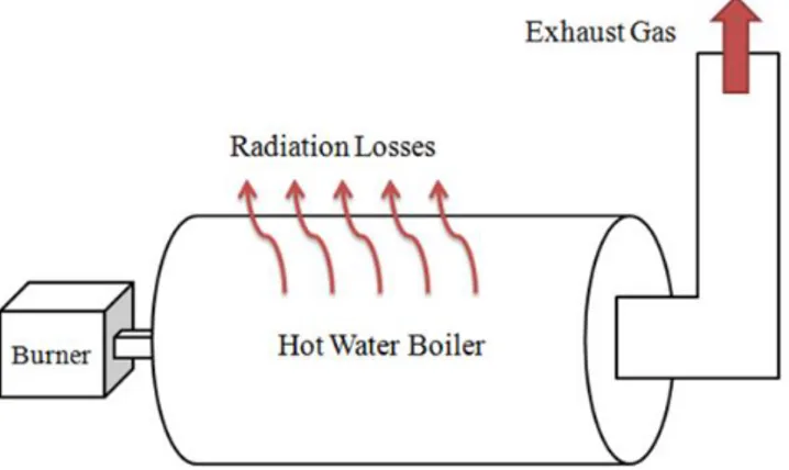
In the present study, recovery of the waste heat from exhaust gases and usage potential of this waste heat was investigated in the central heating plant of the selected university. Schematic diagram and energy losses of the hot water boiler in the central heating plant are shown in Figure 1. The hot water boiler made by stainless steel has 5.5 m length and 2.3 m diameter. Ambient temperature (T0) of the steam boiler room was determined and surface temperature of the hot water boiler (TS) was measured by the multifunctional measuring instrument (TESTO 435) and the thermal camera (TESTO 875-2i), respectively. Since the boiler body was well insulated, surface temperature measurements were taken only from the front and back regions of the boiler. Besides, the components (temperature, CO, O2, CO2 etc.) of the exhaust flue gas were identified by a flue gas analyzer (TESTO 310).
Figure 1. Schematic diagram and energy losses of the hot water boiler
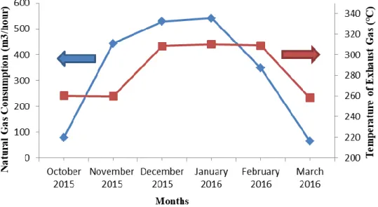
Natural gas is used as fuel in the central heating plant. Natural gas consumption data, measured temperatures of exhaust gas for six months from 2015 to 2016 of the central heating plant are given in Figure 2. As seen, the temperatures of exhaust gas are above the line and directly proportional with natural gas consumption. The total annual fuel consumption and uptime of the boiler are estimated to be about 1 149 748 m3 and 3232 hours, respectively.
Figure 2. Natural gas consumptions and temperatures of exhaust gas of the boiler
It is known from the literature that the average excess oxygen/air rate in a boiling system for a good combustion is in the range of 3-5 % [10]. However, Figure 3 shows that percentage of oxygen values for the selected boiler system are higher than the standards causing higher excess air ratios [11]. This situation obviously indicates that air/fuel ratio of boiler burners should be readjusted to convert the operating range. By this way, over heat losses can be prevented due to the excess combustion.
Figure 3. Variation of % oxygen and carbondioxide with the months
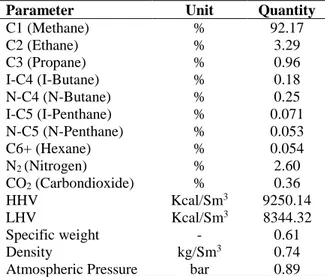
The data for the chemical composition and volume percentage values of the natural gas used in the calculations is received from the localfuel supplier are as shown in Table 1. The closed formula of the used natural gas in accordance with received data is determined as C1.197H4.620O0.0083N0.0599.
Table 1. Physical properties and analysis of natural gas (all the data is provided by fuel supplier)
Parameter Unit Quantity
C1 (Methane) % 92.17 C2 (Ethane) % 3.29 C3 (Propane) % 0.96 I-C4 (I-Butane) % 0.18 N-C4 (N-Butane) % 0.25 I-C5 (I-Penthane) % 0.071 N-C5 (N-Penthane) % 0.053 C6+ (Hexane) % 0.054 N2 (Nitrogen) % 2.60 CO2 (Carbondioxide) % 0.36 HHV Kcal/Sm3 9250.14 LHV Kcal/Sm3 8344.32 Specific weight - 0.61 Density kg/Sm3 0.74
Atmospheric Pressure bar 0.89
3. MEASURED VALUES AND GENERAL MATHEMATICAL TOOLS FOR ANALYSIS
This section gives measured values and mathematical formulas for energy analysis of the hot water boiler. Energy balances are fulfilled around the control volume, determined by the external surface of the hot water boiler. The energy balances are acquired by combination of both average measurement values and calculations based on the following assumptions:
1. The hot water boiler works at steady state conditions.
2. The composition of the natural gas, given in Table 1, and the average inlet of the natural gas at ambient temperature do not change over time.
3. Although surface temperature changes along the hot water boiler, it is accepted that the average surface temperature of hot water boiler (TS, °C) does not change in time.
4. Average surface temperature of the boiler system was calculated by using temperatures of front and back face of the hot water boiler due to the well-insulated of its lateral surface.
5. The average ambient temperature (T0, °C) is constant for every month throughout the study. 6. All gas streams are assumed to be ideal gases [12, 13].
3.1. Energy Losses, Boiler Efficiency and Excess Air Ratio Calculations
Heat losses through flue gases can be analyzed in three parts; dry flue gas, moisture and unburned carbon in the flue gas. Also, some of heat is lost from the surface of the boiler by radiation and convection. Ultimately, all parts of energy losses from the hot water boiler can be calculated from the following equations (Eq.1-8).
Heat loss through dry flue gas (LDFG)
𝐿𝐷𝐹𝐺 = 𝐾 𝑥 (𝑇𝐹𝐺−𝑇0) 𝐶𝑂2 𝑥 𝐻𝐻𝑉 𝐿𝐻𝑉 (1) 𝐾 =69,7 𝑥 𝐶𝑓𝑢𝑒𝑙 𝑥 (𝐿𝐻𝑉)2 (𝐻𝐻𝑉)3 (2)
Heat loss due to unburned carbon in the flue gas (LCOFG) 𝐿𝐶𝑂𝐹𝐺 = 𝐾2 𝑥 𝐶𝑂 𝐶𝑂2+ 𝐶𝑂 𝑥 𝐻𝐻𝑉 𝐿𝐻𝑉 (4) Heat loss from boiler surface by radiation and convection (LRC)
𝐿′𝑅𝐶 = (𝑈𝑟+ 𝑈𝑐)𝑥 𝐴 𝑥 (𝑇𝑆− 𝑇0) (5) 𝑈𝑟 = 𝐸 𝑥 5,67 (𝑇𝑆−𝑇0)𝑥[( 𝑇𝑆 100) 4 − (𝑇0 100) 4 ] (6) 𝑈𝑐 = 𝐵 𝑥 (𝑇𝑆− 𝑇0)0,25 (7) 𝐿𝑅𝐶 = 𝐿𝑅𝐶′ 𝐻𝑒𝑎𝑡 𝑠𝑢𝑝𝑝𝑙𝑖𝑒𝑑 𝑏𝑦 𝑡ℎ𝑒 𝑓𝑢𝑒𝑙𝑥100 (8) Total heat loss (Ltotal) and boiler efficiency (η)
Total heat loss from the hot water boiler is found by the sum of all parts of heat losses according to following equation (Eq.9);
𝐿𝑡𝑜𝑡𝑎𝑙 = 𝐿𝐷𝐹𝐺+ 𝐿𝑀𝐹𝐺+ 𝐿𝐶𝑂𝐹𝐺+ 𝐿𝑅𝐶 (9)
Accordingly, the boiler efficiency can be calculated as follows:
𝜂 = 100 − 𝐿𝑡𝑜𝑡𝑎𝑙 (10) Excess air ratio (λ)
The excess air ratio for a boiler system is directly related to its thermal efficiency. A little excess air ratio is to assure perfect combustion, but large excess air ratio will enhance the flue gas amount [14]. Therefore, it is important that the excess air ratio should be remained in a specific range. The excess air ratio can be calculated by using the measured percentage of oxygen from the following equation (Eq. 11):
𝜆 = 1 + 𝑂2
21−𝑂2 (11) Energy Saving Calculations
A waste heat recovery unit, namely recuperator, was applied to recover the heat loss from the flue gas in the natural gas-fired central heating system. By this way, required quantity of the waste heat to warm up combustion air was recovered.
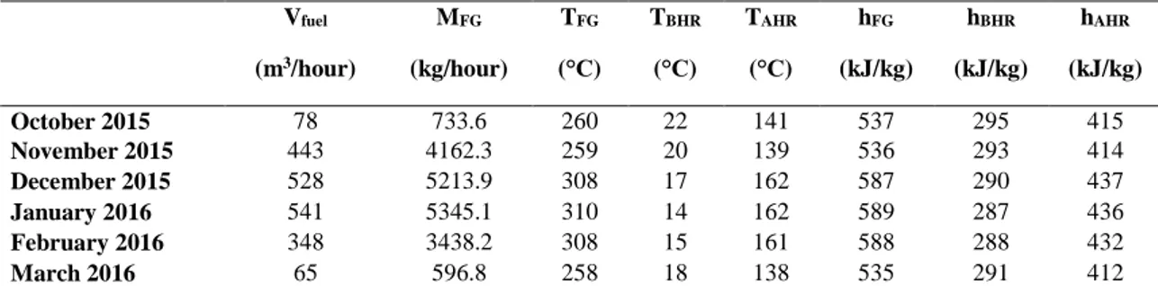
As it already mentioned, all gas streams are assumed to be ideal gases. The average specific heat capacities at constant pressure and fractions of the gas species that compose the exhaust gas, as well as its temperature and enthalpy are shown in Table 2.
Table 2. Energy balance data of the hot water boiler Vfuel (m3/hour) MFG (kg/hour) TFG (°C) TBHR (°C) TAHR (°C) hFG (kJ/kg) hBHR (kJ/kg) hAHR (kJ/kg) October 2015 78 733.6 260 22 141 537 295 415 November 2015 443 4162.3 259 20 139 536 293 414 December 2015 528 5213.9 308 17 162 587 290 437 January 2016 541 5345.1 310 14 162 589 287 436 February 2016 348 3438.2 308 15 161 588 288 432 March 2016 65 596.8 258 18 138 535 291 412
Total potential of the heat energy recovery and natural gas savings can be calculated by using following formulas (Eq. 12-15):
𝑄𝐵𝐻𝑅 = 𝑀𝐹𝐺 𝑥 (ℎ𝐹𝐺− ℎ𝐵𝐻𝑅) (12) 𝑄𝐴𝐻𝑅= 𝑀𝐹𝐺 𝑥 (ℎ𝐹𝐺− ℎ𝐴𝐻𝑅) (13) 𝑄𝑟𝑒𝑐𝑜𝑣𝑒𝑟𝑦 = 𝑄𝐵𝐻𝑅− 𝑄𝐴𝐻𝑅 (14) 𝑁𝑎𝑡𝑢𝑟𝑎𝑙 𝑔𝑎𝑠 𝑠𝑎𝑣𝑖𝑛𝑔𝑠 =𝑄𝑟𝑒𝑐𝑜𝑣𝑒𝑟𝑦 (𝐿𝐻𝑉 𝑥 𝜂) (15) Economic analysis
By using following equations (Eq. 16-17) and data in Table 3, cost savings and payback period for applying recuperator to warm up combustion air of the boiler by reducing flue gas temperature and associated energy savings can be estimated [15].
Savings cost was;
𝑆𝑎𝑣𝑖𝑛𝑔𝑠 𝑐𝑜𝑠𝑡 =Natural gas savings
year x unit price of fuel (16)
Finally, payback period was calculated by the following equation; 𝑃𝑎𝑦𝑏𝑎𝑐𝑘 𝑝𝑒𝑟𝑖𝑜𝑑 =𝐼𝑛𝑣𝑒𝑠𝑡𝑚𝑒𝑛𝑡 𝑐𝑜𝑠𝑡
𝑆𝑎𝑣𝑖𝑛𝑔𝑠 𝑐𝑜𝑠𝑡 (17)
Here, price of the fuel and investment cost of the heat recovery system are around 0.35 $/Sm3 and 10150 $ (contains price of recuperator unit and transfer and setup costs), respectively.
Table 3. Datas for economic analysis Natural gas
saving (Sm3/hour)
Working hours (hours/month)
Natural gas saving (Sm3/month) October 2015 3.00 434 1303 November 2015 17.18 540 9276 December 2015 26.21 620 16249 January 2016 27.23 620 16883 February 2016 16.93 522 8836 March 2016 2.46 496 1221
4. RESULTS AND DISCUSSION
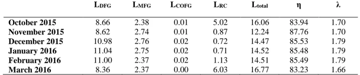
Considering the assumptions as explained in Section 3 and taking the measured data, into consideration energy losses and the hot water boiler efficiency in the central heating plant for six months calculated step by step. Results of heat losses and boiler efficiency calculations are summarized in Table 4.
Table 4. Results of heat losses and boiler efficiency calculations (%)
LDFG LMFG LCOFG LRC Ltotal η λ October 2015 8.66 2.38 0.01 5.02 16.06 83.94 1.70 November 2015 8.62 2.74 0.01 0.87 12.24 87.76 1.70 December 2015 10.98 2.76 0.02 0.72 14.47 85.53 1.79 January 2016 11.04 2.75 0.02 0.71 14.52 85.48 1.79 February 2016 11.00 2.37 0.02 1.13 14.51 85.49 1.79 March 2016 8.36 2.37 0.00 6.03 16.77 83.23 1.66
According to Table 4, a major part of heat losses was due to very high flue gas temperatures. In addition, it is obviously seen that heat losses by radiation and convection from the boiler was in negligible level by comparison with heat losses by high flue gas temperatures because of the well-insulated boiler. Furthermore, together with high flue gas temperatures, higher excess air ratios are another reason for energy losses by increasing the flue gas amount.
The total energy recovery using heat recovery unit, recuperator, was calculated by using related equations (Eq.12-15) and taking measured data from Table 2. The results of heat recovery calculations were given in Table 5 in terms of quantity of energy usage before and after the heat recovery, the quantity of recovered energy, percentage of energy recovery values and lastly natural gas saving amounts for each month.
Table 5. Results of heat recovery calculations QBHR (kJ/hour) QAHR (kJ/hour) Qrecovery (kJ/hour) % Recovery
Natural gas saving (Sm3/hour) October 2015 177490 89445 88045 49.6 3.00 November 2015 1014250 510596 503654 49.7 17.18 December 2015 1551182 782755 768427 49.5 26.21 January 2016 1615242 816841 798401 49.4 27.23 February 2016 1031541 535228 496313 48.1 16.93 March 2016 145816 73617 72199 49.5 2.46
It is clearly seen in Table 5 that the method of the heat recovery from flue gas is one of the effective ways to save energy in the hot water boiler. Although the quantity of recovered energy peaks up the maximum values for December 2015 and January 2016, the percentage of the heat recovery exhibits about half of the total energy for all months.
5. CONCLUSION
The obtained results of the case study about the heat recovery from the flue gases of the hot water boiler in the central heating plant are listed below:
The measured flue gas temperatures of the hot water boiler ranging between 250 °C ~ 300 °C. On the grounds that these temperatures were far above from the standards [11], it was decided to apply heat recovery system.
After that the excess air ratios were calculated by using the measured percentage of oxygen in the flue gas for six months, it can be clearly seen from the results that large excess air ratios were in existence causing excess flue gas amount.
Heat losses from the flue gas of the hot water boiler varied between 10% ~ 14%. The annual amount of waste heat from the flue gas of the hot water boiler to the atmosphere was 421 235 041 kJ/year.
The total annual fuel consumption of the hot water boiler and its monetary value were estimated to be about 1 149 748 m3 and 402 412 $, respectively. Natural gas savings by applying recuperator for preheating combustion air and its monetary value were calculated 53 768 m3/year (44.86 TOE/year) and 18 711 $/year, respectively. By taking this precaution, energy savings can be achieved up to 50 %.
Investment cost and payback period for heat recovery system in the hot water boiler system were found to be 10 150 $ and 6.5 months, respectively, which is economically very viable.
Nomenclatures
A Surface area of related region of boiler (m2)
B Surface coefficient (1.20 for horizontal cylinder)
Cfuel Total carbon ratio in the fuel (%) CO CO ratio in the flue gas (%)
CO2 CO2 ratio in the flue gas (%)
E Emissivity coefficient (0.77)
hAHR Enthalpy @ average temperature (kJ/kg) hBHR Enthalpy @ ambient temperature (kJ/kg) hFG Enthalpy @ flue gas temperature (kJ/kg) H2 H2 ratio in the flue gas (%)
HHV Higher heating value (kcal/kg)
K2 Constant (32 for natural gas)
LCOFG Heat loss due to unburned carbon in the flue gas (%) LDFG Heat loss through dry flue gas (%)
LMFG Heat loss due to moisture in the flue gas (%)
LRC Heat loss from boiler surface by radiation and convection (%)
Ltotal Total heat loss (%)
LHV Lower heating value (kcal/kg)
MFG Flow rate of flue gas (kg/hour) O2 O2 ratio in the flue gas (%)
QAHR Using heat after heat recovery (kJ/hour) QBHR Using heat before heat recovery (kJ/hour) Qrecovery Recovered heat by recuperator (kJ/hour)
T0 Ambient temperature (°C)
TS Surface temperature of the hot water boiler (°C) TFG Flue gas temperature (°C)
Uc Total heat transfer coefficient for convection (watt/m2 K) Ur Total heat transfer coefficient for radiation (watt/m2 K) Vfuel Fuel consumption (m3/hour)
Greek Symbols
η Boiler efficiency (%)
ACKNOWLEDGMENTS
The authors would like to thank the financial support provided by the Mevlana Development Agency, Konya- Karaman, Turkey (MEVKA) under the project no TR52/15/YNRKG1/0013. We also would like to express their gratitude to the Scientific Research Commission of Karamanoğlu Mehmetbey University for financial support under the project no 24-M-16.
REFERENCES
[1] Zhou N, Wang X, Chen Z and Wang Z. Experimental study on organic rankine cycle for waste heat recovery from low-temperature flue gas. Energy 2013; 55: 216–225.
[2] Lian H, Li Y, Shu G and Gu C. An overview of domestic technologies for waste heat utilization. Energy Conserv. Technol. 2011; 29: 123–128.
[3] Latour S, Menningmann J and Blanney B. Waste heat recovery potential in selected industries. 1982.
[4] Saidur R, Ahamed JU and Masjuki HH. Energy, exergy and economic analysis of industrial boilers. Energy Policy 2010; 38: 2188–2197.
[5] Beggs C. Energy Management, Supply and Conservation. Amsterdam: Elsevier Ltd, 2002. [6] Jayamaha L. Energy Efficient Building Systems. Europe: Mcgraw Hill Education, 2008.
[7] Niamsuwan S, Kittisupakorn P and Mujtaba IM. A newly designed economizer to improve waste heat recovery: A case study in a pasteurized milk plant. Appl. Therm. Eng. 2013; 60:188–199. [8] Wang C et al. Application of a low pressure economizer for waste heat recovery from the exhaust
flue gas in a 600 MW power plant. Energy. 2012; 48: 196–202.
[9] Utlu Z. Investigation of the potential for heat recovery at low, medium, and high stages in the Turkish industrial sector (TIS): An application. Energy. 2015; 81: 394–405.
[10] Kuprianov VI. Applications of a cost-based method of excess air optimization for the improvement of thermal efficiency and environmental performance of steam boilers. Renew. Sustain. Energy Rev. 2005; 9: 474–498.
[11] Hepbasli A. Energy Efficiency And Management System, (Elsevier), İstanbul, 2010.
[12]
Celep GK, Rüşen SE. Application of economizer for waste heat recovery from exhaust flue gas in steam boiler: a case study in a biscuit factory. 4th International symposium on ınnovative technologies in engineering and science (ISITES), 2016, Antalya.[13] Karanfil G, Rüşen SE. The Waste Heat Recovery in the Furnace: a Case Study in a Biscuit Factory. International conference on material science and technology (IMSTEC), 2016, Nevşehir. [14] Zhu K, Xia J, Xie X, and Jiang Y. Total heat recovery of gas boiler by absorption heat pump and
direct-contact heat exchanger. Appl. Therm. Eng. 2014; 71: 213–218.
[15] Rusen SE, Topcu, MA, Celtek, SA, Karanfil Celep, G, Rusen, A. Investigation of energy saving potentials of a food factory by energy audit. J Eng. Reseac. and Appl. Sci. 2018; 7 (1): 848-860.