Nevşehir Bilim ve Teknoloji Dergisi
Araştırma Makalesi (Research Article)
Makale Doi: 10.17100/nevbiltek.403822
Geliş Tarihi:09-03-2018 Kabul Tarihi03-12-2020
The Effects of the Electrode Type on Microstructure and Hardness of the RSW of DP600
Steel
Bilge DEMİR 1, , Muhammed ELİTAŞ 2*, Hüseyin KARAKUŞ 3
1Karabük Üniversitesi, Mühendislik Fakültesi, Makine Mühendisliği Bölümü, Karabük ORCID ID: 0000-0002-3617-9749
2Karabük Üniversitesi, Teknoloji Fakültesi, İmalat Mühendisliği Bölümü, Karabük ORCID ID: 0000-0001-5358-1783
3Karabük Üniversitesi, Teknoloji Fakültesi, İmalat Mühendisliği Bölümü, Karabük ORCID ID: 0000-0000-0000-0000
Abstract
In this paper, the effects of the electrode type on microstructure and hardness of the resistance spot welded junctions of DP600 steel are investigated. Commercial galvanized DP600 sheet steel is used. Resistance spot welding (RSW), with changing electrode type according to geometry, are conducted at constant weld time, weld current and weld pressure. Microstructure and hardness formation in weld zone during resistance spot welding are happen essentially depend on materials properties and weld parameters particularly on heat input. We can mention many factors that influence heat input, but essentially welding current and welding time are more effective than others. On the other hand, Electrode tip type which has big effect on weld quality, is also affect welding contact and so heat transfer during in RSW. Experimental results of this study showed that particularly a spherical type electrode have caused low heat input and thus minor microstructure changes at heat affected zone (HAZ) have been observed. As results detailly explanations have been made according to electrode type and microstructure of the weld zone.
Keywords: DP600; Resistance Rpot Welding; Microstructure; Hardness.
Elektrot Tipinin Nokta Direnç Kaynaklı DP600 Çeliğinin Mikroyapı ve Sertliğine Etkileri
Öz
Bu çalışmada, elektrot tipinin DP600 çeliğinin nokta direnç kaynaklı birleşimlerinin mikroyapı ve sertliği üzerindeki etkileri incelenmiştir. Ticari galvanizli DP600 sac çeliği kullanılmıştır. Nokta direnç kaynağı (NDK), geometriye göre değişen elektrot tiplerinde, sabit kaynak süresi, kaynak akımı ve kaynak basıncında gerçekleştirilmiştir. Nokta direnç kaynağı sırasında kaynak bölgesinde mikroyapı ve sertlik oluşumu esas olarak malzeme özelliklerine ve özellikle ısı girdisi olmak üzere kaynak parametrelerine bağlıdır. Isı girdisini etkileyen birçok faktörden bahsedebiliriz, ancak esasen kaynak akımı ve kaynak süresi diğerlerinden daha etkilidir. Öte yandan kaynak kalitesine büyük etkisi olan Elektrot uç tipi de kaynak temasını ve dolayısıyla NDK sırasında ısı transferini etkiler. Sonuçlar, özellikle küresel tip elektrotun düşük ısı girdisi meydana getirdiğini, dolayısıyla ısıdan etkilenen bölgede (ITAB) sınırlı mikroyapı değişiminin olduğunu göstermiştir. Sonuç olarak, elektrot tipine ve kaynak bölgesinin mikroyapısına göre detaylı açıklamalar yapılmıştır.
Anahtar Kelimeler: DP600; Nokta Direnç Kaynağı; Mikroyapı; Sertlik.
182
1. Introduction
An increase in fuel price force automotive industry to find better structural materials to achieve enhanced lightweight structures. To reduce the part weight is top target of all manufacturer particularly automobile manufacturer. To achieve this aim, instead of the low quality materials, using of the polymers materials, composite materials, aluminum alloys and advanced high strength steels (AHSS) have been increasing day by day [1]. AHSS are defined and classified according to their metallurgical properties such as phases in microstructure, strength level, and manufacturing processes. Very common classes of advanced steels are Dual phase (DP), transformation induced plasticity steel (TRIP), ferritic-bainitic steel, complex phase steel, Twinning-Induced Plasticity (TWIP) steel and so forth [2]. When compare to classic high strength steels, advanced steels have higher yield and tensile strength yield ratio (yield strength ratio to tensile strength) higher uniform and total ductility and toughness and good formability, higher work hardening rate etc. [3]. In this regard, AHSS have unique properties in meaning of as automobile sheet steels and the best choice for manufacturing process of the in weight vehicle [4]. AHSS are produced generally made using inter critical annealing and fast cooling or moderate cooling and austenizing and then moderate cooling. Depending on using different alloying elements and heat treatment parameters and conditions, AHSS would be have proper microphases in their microstructure [3,5,6].
Dual phase steel which is in first generation, famous and widely used sort of advanced steel [7 and 8]. Generally, carbon content of the dual phase steel is between 0.05-0.2% and Mangan content is higher than 1.5% [9]. Dual phase steels have been used for made of automotive parts’ chassis, wheel, bumper etc. which is need to higher strength and ductility relationship. The higher strength-ductility relationship is come from mixing of ferrite and martensite microstructure of dual phase steel which is gained by partial austenization and then cooling. [10-12]. Producing of the dual phase steel has some specific and unique characteristics. For example, transformation of the austenite phase to martensite during cooling from intercritical annealing leads to volume expanding and therefore cause to formation of the higher amount mobile dislocation density at ferrite phases adjacent areas to martensite particules. Early and continues yielding deformation behavior of dual phase steel have been explained by this higher dislocation density [13-15]. At the same time, this dislocation density is assumed as an essential reason for good formability of dual phase steel together with purity of ductile ferrite phase and tough and strong martensite particulates [16].
AHSS could be joined by using various welding methods such as resistance welding, arc welding and so forth. However for sheet and car body conjunctions, resistance spot welding method is more feasible and available, due to not needed to extra filler material and due to appropriate to robotic welding and so automation. A car body may comprise higher than even 5000 spot welding points [2 and 5]. Resistance spot welding (RSW) is explained by Joule effect that resulted from local heating of two or three overlapped sheet under conditions of the resistance to electric transition and electrode pressure [17]. RSW could be defined as a process having heating, melting and solidification of the weld zone. This process cycle disturbs and changes the microstructure of weld zone. Therefore, understanding of these changes come to meaning of the understand the new structure, so new properties of the weld metal [18-20]. In other word, for successfully using of advanced steel in industry particularly automotive, RSW phenomenon of the advanced steel must be understood and characterized very well. Eventually, it would be assumed that Structural performance of the auto’s body is depending on structural satisfying of the welded junctions [21 and 22].
Dual phase steels microstructure is consist of BCC ferrite and BCT martensite [9,16,23-29]. However, as results of the heat cycle during RSW, weld metal could shows higher hardenability of the DP sheet material and thus martensite phases are dominant and general grain dimensions and martensite particle size are also increases. Microstructure’s phases , ferrite and martensite rearranged by heat cycle. During weld heat increasing at HAZ, there is a temperature gradient. Th gradient makes pic at adherent location to weld metal. When fusion zone melt and solidified, HAZ don’t show melting
183
but show near temperature. A temperature gradient occurs in the HAZ region. While the gradient is maximum in the regions close to the weld metal, A1 temperature decreases to the lower limit as it goes to the base metal. As a result, the thermal cycle that occurs with the heating and cooling during the welding process, after the high amount of austenite cooling in the regions close to the weld metal, martensite and the base metal gradually form the austenite and ferrite, and after cooling, martensite and ferrite form the dual phase structure. Previous researchers have been explained this situation as a results of uncompleted austenite transformation [29-33].Generally, at resistance spot welding if sheet thickness larger than 2 mm and solidification time of fusion zone is lower than 3-4 weld cycle [34]. Cooling rate is changing between; for 2 mm sheet thickness is 2000 °C/s and for 0.5 mm sheet thickness is 105 °C/s [35]. This cooling rate for samples of RSW junction, it means that this cooling rate much higher than required cooling rate for martensitic transformation. It is known that for general commercial DP steels factory-hardening cooling rate nearly 40-120 °C/s. [32]. Therefore, it is assumed that RSW heating and cooling condition are enough to martensitic transformation at weld zone of RSW [33]. According to a research this martensitic transformation is very effective on hardness in DP steels, in fact that increasing of the hardness in weld zone could be two-time higher than base metal (420 HV) [4].
Hardness is a strength criterion and shows resistance level to loading on materials. Lots of material’s properties such as plasticity, elasticity and their all related properties are also strongly related with hardness. Hardness value are changeably by using vary heat treatment methods, heat condition and processing. For example, full annealing conditions improves ductility and decrease hardness. by that, it causes to lower strength, but steel is come to easy formable materials . Generally, it is used for low carbon and middle carbon steel. Normalization heat treatment make steel as a strong and harder materials than full annealing. Other that, Quenching is a strengthening method and its application is consisting of full austenizing at normalizing temperature and then quenching by using enough cooling rate. All about heat treatments are strictly depending on to steel chemicals compositions. All of this condition would be occur during welding process if in which annealing and then cooling possible. Chemical composition and cooling rate have an defining role on microstructure and hardness. In addition to that lots of manufacturing process also have heat and cooling cycle and therefore all condition above could be mentioned for them. Controlled manufacturing is better in meaning heat-cooling cycles. By this, we can arrange to microstructure and hardness and thus mechanical properties. All this condition about heat treatment condition is appropriate to also resistance spot welding process. This process proves higher hardness in dual phase and general advanced steel due to higher hardening properties of the DP steel [36]. Hardness has big effect on general mechanical properties so investigation on hardness for all processes gives useful knowledge. In the fact that, advanced steel is generally produced by special chemical composition, heat, and cooling cycle. Therefore, during manufacturing, secondly exposing to similar condition is forming new microstructure and hardness. This new structure is very different than before and understanding and defining of this new one is very important for design and application. Many researchers [36-46] have studied on hardness changing after manufacturing processes particularly viewing of the welding as a process has heat and cooling cycle. At fallows, some of them are given as example. Valesaco [37], reported that stainless steel used in concrete building, welding process has a big effect on hardness and local changing of hardness would be important [37]. Some materials would be hardened before selling such as hardox sheet. Frydman [38] studied on hardox because of their quenched and tempered structures, He reported that welding cause to decrease to hardness so must be considered during design and service condition. Zieman at his study [39], emphasized that the same mentions with him. A study, with using ASTM-A529 steel containing Carbon, Mangan and has ultra-refined grain size used for short gun barrel. They welded this material with friction stir welding method and reported that hardness changing very effective [39 and 40]. Gural et al. [41] used different way to observe that they produced dual phase steel structure after welding and thus they aimed that decrease to welding processes on hardness and microstructure using ASTM 1010
184
steel grade and controlled atmosphere condition [41]. Acarer and Demir [42] welded dual phase steel to Al alloy sheet by using explosive welding. They reported that also in explosive welding at weld metal hardness is increasing [42]. Abdullah and Siddiqui [43] investigated the effect of the laser welding parameters on hardness with using low alloy steel and pre-annealing-last annealing. Klobcar [44], Li [45] also studied on hardness of welded materials. Hayat et. al. [46 and 47], researched resistance spot welded of IF and dual phase steels. They reported that RSW samples showed significant differences in hardness distributions between weld metal, HAZ and the base metal.Hardness has strongly influence on mechanical properties and there is not enough study on RSW electrode tip type effect on welding, that is way this study was carried out. With this study, four different RSW electrode tip types were used and investigated for understanding to hardness and microstructure changing of RSW samples. Selected electrode was made of industrial Cu electrode materials. Their using may content some specific condition but the same time also all of them are useable in the same processes, as this paper.
2. Material and Methods
2.1. Material
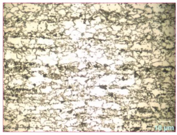
In this study, commercial galvanized DP600 steel sheet having 1.2 mm thickness was used. Chemical composition of this steel sheet has been showed at Table 1 and microstructure have been giving at Figure 1. DP600 steel has two micro phases as ferrite and martensite which could be selected in this figure clearlly. DP600 sheet is called with their strength level in commercially. Therefore, 600 is meaning of the 600 MPa the tensile strength of DP sheet steel.
Figure 1. Microstructure of DP600 steel Table 1. Chemical composition of DP600 steel (%)
Steel C Si Mn S Cr Ni Al Ti V Sn Fe
DP600 0.077 0.253 1.86 0.006 0.177 0.012 0.127 0.002 0.004 0.006 97.472
2.2. Test Specimen and Spot Welding Conditions
Resistance spot welding samples is prepared as 30x30x1.2 dimensions seen at Figure 2. This Figure also shows that welding positions as overlapped samples. Resistance welding electrodes were made of commercial Cu and their detailly chemical composition have been given at Table 2.
185
Figure 2. Schematic appearance of the welding samples and weld positionTable 2. Chemical composition of electrode (% weight)
Cu Zn P Fe S Mn Al Ni
99.4 0.0115 0.0144 0.0207 0.150 0.0062 0.0054 0.0050
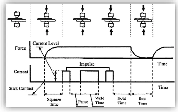
Resistance welding electrode have been produced in four different tip forms by turning process. These four different electrodes tip types technical drawings have been given at Figure 3. Resistance spot welding machine was semi-automatic, and its parameters such as weld current, weld time, weld pressure, and water-cooling system were controllable. At least three samples were prepared and tested for each group and parameter. Before welding, sample’s surfaces were cleaned by chemical agent against any surface dirty and failure such as oil, dust, etc. Welding process had been applied using constant 5 kA weld current, 20 cycle weld time and 6 bar electrode pressure. Schematic seeming of the resistance welding process diagram in this study is given at Table 3 and Figure 4.
Figure 3. Technical drawings of electrode tip types a) Flat R6 b) Conical R3 c) Conical round d) Flat conical Table 3. Parameters of welding process
Electrode tip type Welding current, kA Welding time, cycle Electrode pressure, bar
Flat R6 5 20 6
Conical R3 5 20 6
Conical round 5 20 6
186
Figure 4. The schematic diagram of welding process used in this studyDuring all welding processes, to keep the welding nugget from deteriorating due to pressure and electrode slippage, the wood mold was used to keep the overlapping point of resistance welding samples stable. This was specifically designed for spot weld samples as wood mold. This wood mold has fixed to samples and covered all side of its.
2.3. Metallographic Study and Microhardness Testing
Cross-section of welded samples were prepared by following standards metallographic procedures for metallographic examination and hardness test measurement. Polished samples surface was etched by using %2 nital etchant (2% nitric aside + %98 methanol). Optic study and weld nugget measuring were carried out by utilizing Nikon Epiphote 200 microscope and a stereo microscope. Hardness measurement points on surface of the RSW samples were given schematically at Figure 5. Microhardness measurements were performed by using Qness Q10A+ microhardness machine with 1000gr's load.
Figure 5. Welded samples’ plain appearance with hardness test points
3. Results
3.1. Microstructure
To understand the welding microstructure after welding and the effect of welding microstructure on welding properties and performance, it is necessary to understand basic material properties and the effect of heat input on welding properties. Therefore, it could be said that the crucial considering point in that, is the local results and the changing areas from heat input of welding. In the fact that, microstructural analyses come to prominent position related with explanation of the RSW nugget properties [2]. As mentioned before, and reported in open literature, the most important characteristic of advanced high strength steels is to come their properties from their microstructures and, with posing to heat input during manufacturing process such as welding or repairing operation, are change their structure [2].
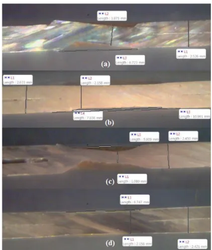
Used materials in this study was a commercial dual phase steel having ferrite and martensite content in microstructure This steel comprise high Mn alloying content as seen Table 2., which could prove enough hardenability during cooling after intercritical annealing. Other conditions related with explaining to changing in microstructure during welding are heat input and reached temperature. Macrostructures of the RSW weld samples were given at Figure 6 with different
187
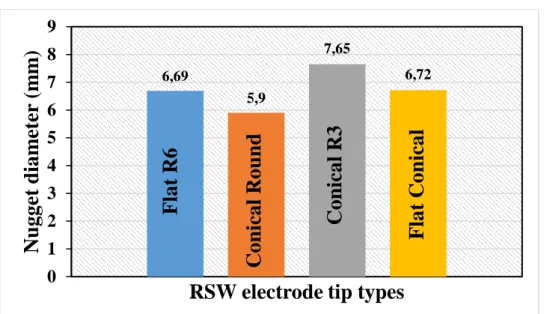
electrode tip types as a) flat conical b) conical R3 c) conical round d) flat R6, and with their dimension measurement lever. In addition to that, at Figure 7. Nugget dimensions changes vs RSW electrode tips and at Figure 8. resulted microstructures of the RSW samples were given. As seen at Figure 6. The little RSW nugget thickness was obtained at RSW with conical round electrode. However, the thicker thickness was obtained at flat R6 electrode. These results could be explained with contact area of the electrode with samples during welding. Flat R6 electrode gives bigger contact area so better and thus prove homogeneous the electric distribution and resistance. Bigger weld nugget was obtained at conical R3 electrode which has wide contact area. In all weld metal microstructures were formed by dominantly martensite and may little bainite, however separate to bainite from martensite is a much difficult study due to mix. microstructure. However, defining microstructure of the dual phase steel in meaning just matrix structure and second phase could be clearly observed . Important effective phenomenon on formation and morphology of microstrucrure of dual phase steel during RSW are heat input and contact area of the RSW electrode type. As seen Figures 6.-8. electrode type directly affect to growing of weld nugget, geometry and microstructure morphology. Therefore, to obtain available nugget performance, optimization of these factors effect are very important studies in RSW processes.In this study, differences in RSW nugget, due to various RSW electrode tip types clearly have shown by the results. In addition similar study to this research not haven’t found in open literature. Therefore, discussion comparing with the literature have been made limitedly in this study.Essentially, RSW electrode tip types have been very effective on RSW nugget geometry according to results have been showed at Figure 6-8 but. Besides that, effect of the electrode tip types on RSW nugget microstructure could be accepted nearly similar, the reason of this phenomena, microstructures of the RSW nuggets for all samples have shown martensite phases at fusion zone and it shows a microstructure that transforms from martensite to dual phase structure at varying rates as we go from the melting zone to the base metal. Figure 8 clearly shows these conditions.
188
Figure 7. Nugget width obtained at different electrode tip types and at 5 kA welding currenta) b)
c) d)
Figure 8. Microstructure images obtained at different electrode tip types a) conical round b) flat conical
c) flat R6 d) conical R3 (not magnification scale of the zoomed structure is similar)
Here we could say that as mentioned before, all microstructural changings are dependent on material properties of DP steel properly hardenability of this steel material, because of the high Mangan content and enough Carbon content and with weld zones heat input which leads to melting during welding processes [7,9,]. Cooling after melting has austenite formation at austenite region and austenite and ferrite at intercritical annealing region but this is too short due to fast cooling. This is short because during cooling for ferrite formation from austenite needs to more time [16,23-29]. However, due to fast cooling depending also on water cooling of electrode and high heat transfer of copper electrode during holding stage and time after melting cooling of welded samples is very fast. During this period, due to insufficient time to carbon deprivation in austenite meaning diffusion to out of it is not occur effectively. In other words, critical cooling rate require
6,69 5,9 7,65 6,72
0
1
2
3
4
5
6
7
8
9
N
ug
g
et
di
a
m
eter
(m
m
)
RSW electrode tip types
F
la
t
R
6
C
o
ni
ca
l
R
o
und
C
o
ni
ca
l
R
3
F
la
t
C
o
ni
ca
l
189
for austenite transformation to martensite in this material due to alloying elements is not high and air cooling and water cooling of electrode are enough for this [9,30,31,33]. Double effect of these lead to hardening in weld metal and HAZ.HAZ of the samples also have showed more martensite phase and its volume fraction have been changing from weld metal to base metal as mentioned before. Near to weld metal fully martensite and near to base metal dual phase steel like base metal as results of temperature gradient at this zone. Consequently, for HAZ, all this microstructure results arise from the thermal gradient which is occurred from weld metal to base metal. Understanding of this with comparing with chemical composition of the materials can explain a lot of conditions in microstructure and mechanical properties of the junctions.
3.2. Microhardness Results
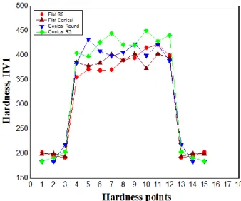
Because of the microstructure and alloy content of the materials, hardness of the materials has shown varies. For dual phase steel, the hardest phases are martensite and bainite together with needle protectoit ferrite . Thus, as well known, if any steel has got martensite and bainite is quite harder. In addition to that alloying elements particularly Mn lead to good hardenability and so high hardness. Materials used in this study comprise all this, both of before welding and after welding. Base metal has high hardness than to be required depending on alloying content and dual phase process. therefore, weld zones have shown also higher hardness after welding too as seen at Figure 9. In other words, martensite is good barrier to resist against to dislocation slip actions and movements. During welding processes, very fast heating, and cooling cycle lead to austenite to martensite transformation. In welding, as explained above, weld metal of RSW cools from austenite phases, even some HAZ also cool from austenite and thus these zones have shown higher hardness than base metal, dual phase steel. Some region at HAZ cool from inter-critical area of the temperatures so these are having two phases, ferrite, and martensite [9 and 48]. Another important phenomena is tempering at base metal adherent area to HAZ. However, don’t seen any microstructural change due to lower temperature than Ar1, closed area of base metal to HAZ is exposed to tempering. This is also very important for all properties because of the failure effect of the tempering softening. However, in literature, there are not enough study on that, but several studies shortly mentioned [2]. This effect could be described tempering of the dual phase steel. At this point, there is another important case is that martensite volume fraction essentially less and the effect of decreasing of hardness in this zone may have been seen more. For defining, that is required to detailly and closely hardness measurement. Hardness map constructing may show this condition better than all other hardness graphics. At this study’s facilities have not got feasible facilities meaning of the detailly hardness measurements.
190
Thus, hardness values of the samples, according to literature they are in usable gap for all tip type. To explain hardness depending martensite and bainite are true way [2,4,7,33]. Pal et. all [9], reported that, increasing of heat input increases also generation of the higher amount of martensite deformation induction cause to higher hardness [9]. According to Callister [49], hardness of martensite, in case exceeding 0.05% mass of carbon content, is expected to be more than 350 HV. In this study, it was calculated that carbon contents of the steel sheet materials were appropriate to this rule. And so, experimentally measured hardness of samples has affirmed to that. That, all weld metal hardness of the samples of different electrode tip types have shown higher hardness value than 350 HV as seen Figure 9. Higher hardness values have been observed at weld metal of the Conical R3 electrode tip type sample. Secondly, highest hardness values have been observed at weld metal of the Conical Round electrode tip type. Moreover, Conical R3 electrode showed more hardness like showed also bigger nugget thickness. These are probable due to their high-pressure effect depending on conical and rounded shape of them and so may grain refinement effect of them, in literature there are not any knowledge about them particularly advanced steels for different electrode tip types.4. Conclusions
In this study, in conditions of constant weld parameters and using four different electrode tip types, resistance spot welding of the commercial DP600 steel have been studied in meaning of the hardness and microstructure because of their big determinative effect on mechanical properties. Following conditions are drawn.:
1. Essentially, even though they were welded with different types of electrodes, all RSW samples have showed intensely martensite phases and may some bainite phase structures in the weld zone.
2. Moving from the weld metal to the base metal in the HAZ region, the amount of martensite decreases while the amount of protectoit ferrite increases. In addition, it is possible to find tempered martensite and ferrite structures in the base metal regions adjacent to HAZ by the effect of tempering.
3. Generally, for all samples it could be said that hardness of weld metal has more harder than base metal and HAZ. However, some difference is observed locally differences which could be interpreted due to harder phase localization.
4. Hardness of metals has been measured highest hardness value at Conical R3 sample. Lower hardness value has been measured at Flat R6 sample. HAZ hardness of these have shown the same trend and value when compared.
5. Acknowledgements
We would like to thank the Karabuk University Rectorate and BAP Project Coordinator for supporting this work.
6. References
[1] Kelkar A., Roth R., Clarl J., “Can aluminum be an economical alternative to steel” JOM, 53(8), 28–32, 2001. [2] Khan M.I., Kuntz M.L., Biro E., Zhou Y. “Microstructure and mechanical properties of resistance spot welded
advanced high strength steels” Materials Transactions, 49(7), 1629-1637, 2008.
[3] Long X., Khanna S.K., “Fatigue properties and failure characterization of spot welded high strength steel sheet”
International Journal of Fatigue, 29, 879-886, 2007.
[4] Ma C., Chen D.L., Bhole S.D., Boudreau G., Lee A., Biro E., “Microstructure and fracture characteristics of spot-welded DP600 steel” Materials Science and Engineering A, 485, 334-346, 2008.
191
[5] Alzahougi A., Elitas M., Demir B., “RSW junctions of advanced automotive sheet steel by using differentelectrode pressures” Engineering, Technology & Applied Science Research, 8(5), 3492-3495, 2018.
[6] Lindgren C., Sperle J.O., Jonsson M., “Fatigue strength of spot-welded beams in high strength steels” Weld
World, 37(1), 90–104, 1996.
[7] Holovenko O., Lenco M.G., Pastore E., Pinasco M.R., Matteis P., Scavino G., Firrao D., “Microstructural and mechanical characterization of welded joints on innovative high-strength steels” La Metallurgia Italiana, 3, 3-12, 2013.
[8] Harvath C.D., “The future revolution in automotive high strength steel usage, proc.” Great Design in Steel Conf., Michigan, 2004.
[9] Pal T.K., Bhowmick K., “Resistance spot welding characteristics and high cycle fatigue behavior of DP780 steel sheet” ASM International, 21, 280-285, 2012.
[10] Speich G.R., “Dual-phase steels”, in: J.R. Davis et al. (eds.), ASM Handbook, 424- 429s, Ohio, 1990.
[11] CEN prEN 10338, “Cold rolled flat products of multiphase steels for cold forming - technical delivery conditions” Bruxelles, 2010.
[12] Ghanheri A., Shafyei A., Honarmand M., “Effects of inter-critical temperatures on martensite morphology, volume fraction and mechanical properties of dual phase steels obtained from direct and continuous annealing cycles” Materials & Design, 62, 305–19, 2014.
[13] Farabi N., Chen D., Zhou Y., “Fatigue properties of laser welded dual-phase steel joints” Procedia Engineering, 2, 835–43, 2010.
[14] Committee on Automotive Applications. Advanced high strength steel (AHSS) Application Guidelines. Brussels: International Iron and Steel Institute; 2005.
[15] Sarwar M., Priestner R., “Influence of ferrite–martensite microstructural morphology on tensile properties of dual-phase steel” Journal of Materials Science, 31, 2091–5, 1996.
[16] Technical Transfer Dispatch #6—Body Structure Materials, ULSAB-AVC Consortium, 2001.
[17] Williams N.T., “Resistance spot welding”, in: D.L. Olson et al. (eds.), ASM Handbook, 226 – 229s, Ohio, 1993. [18] Khan M.I., Kuntz M.L., Su P., Gerlich A., North T., Zhou Y., “Resistance and friction stir spot welding of
DP600: a comparative study” Science and Technology of Welding and Joining, 12(2), 175-182, 2007. [19] Shi G., Westgate S.A., “Optimizing welding conditions for TRIP steels” TWI bulletin, 2006.
[20] Ghosh P.K., Gupta P.C., Avtar R., Jha B.K., “Weldability of intercritical annealed dual-phase steel with the resistance spot welding process” Welding Journal, 70(1), 7-14, 1991.
[21] Riesner M., Sun X., Wu S., Hwang, H.Y., Low E., “Modeling and optimizing of structural joints in automotive applications” Proc. of the Int. Crashworthiness Conf., London, 2000.
[22] Sun X., Dong P., “Analysis of aluminum resistance spot welding processes using coupled finite element procedures” Welding Journal, 79(8), 215–221, 2000.
[23] Williams N.T., Parker J.D., “Review of resistance spot welding of steel sheets part 1 modelling and control of weld nugget formation” International Materials Reviews, 2, 45–75, 2004.
[24] Chien C.S., Kannatey E., Asibu J.R., “Investigation of monitoring systems for resistance spot welding” Welding
192
[25] Senkara J., Zhang H., Hu S.J., “Expulsion prediction in resistance spot welding” Welding Journal, 83, 123–132,2004.
[26] Zhang H., “Expulsion and its influence on weld quality” Welding Research Supplement, 11, 373–380, 1999. [27] Elitas M., Demir B., “The effects of the welding parameters on tensile properties of RSW junctions of DP1000
sheet steel” Engineering, Technology & Applied Science Research, 8(4), 3116-3120, 2018.
[28] Wang G., Barkey M.E., “Investigating the spot weld fatigue crack growth process using X-ray imaging” Welding
Journal, 85, 84–90, 2006.
[29] Marya M., Gayden X.Q., “Development of requirements for resistance spot welding dual-phase (DP600) steels part 1-the causes of interfacial fracture” Welding Journal, 84, 172-182, 2005.
[30] El-Sayed M.E., Stawiarski T., Frutiger R., “Fatigue analysis of spot welded joints under variable amplitude load history” Engineering Fracture Mechanics, 55(3), 363–369, 1996.
[31] Gould J.E., Khurana S.P., Li T., “Prediction of microstructures when welding automotive advanced high-strength steels” Welding Journal, 85, 111–116, 2006.
[32] Easterling K., “Introduction to the Physical Metallurgy of Welding”, second ed., Butterworth Heinemann Ltd., Oxford, 1992.
[33] Gould J.E., Khurana S.P., Li T., “Prediction of microstructures when welding automotive advanced high-strength steels” Welding Journal, 85, 111–116, 2006.
[34] Tumuluru M. D., Great Designs in Steel Conference, T4-8, MI, 2006.
[35] Adams C. M., “Cooling rates and peak temperatures in fusion welding” Welding Journal, 37(5), 210–215, 1958. [36] Li Z., Duan Y., Zhang M., Shi M., Zhu F., Zhang S., “Effects of quenching process on mechanical properties
and microstructure of high strength steel” Journal of Wuhan University of Technology-Mater. Sci. Ed., 27(6), 1024-1028, 2012.
[37] Velasco F., Blanco G., Bautista A., Martínez M., “Effect of welding on local mechanical properties of stainless steels for concrete structures using universal hardness tests” Construction and Building Materials, 23(5), 1883-1891, 2009.
[38] Frydman S., Konat Ł., Pękalski G., “Structure and hardness changes in welded joints of Hardox steels” Archives
of Civil and Mechanical Engineering, 8(4), 15-27, 2008.
[39] Ziemian C.W., Sharma M.M., Whaley D.E., “Effects of flashing and upset sequences on microstructure, hardness, and tensile properties of welded structural steel joints” Materials & Design, 33, 175-184, 2012. [40] Ueji R., Fujii H., Cui L., Nishioka A., Kunishige K., Nogi K., “Friction stir welding of ultrafine grained plain
low-carbon steel formed by the martensite process” Materials Science and Engineering A, 423(1), 324-330, 2006.
[41] Güral A., Bostan., B; Özdemir A., “Heat treatment in two phase regions and its effect on microstructure and mechanical strength after welding of a low carbon steel” Materials & Design, 28(3), 897-903, 2007.
[42] Acarer M., Demir B., “An investigation of mechanical and metallurgical properties of explosive welded aluminum–dual phase steel” Materials Letters, 62(25), 4158-4160, 2008.
[43] Abdullah H.A., Siddiqui R.A., “Concurrent laser welding and annealing exploiting robotically manipulated optical fibers” Optics and lasers in engineering, 38(6), 473-484, 2002.
[44] Klobčar D., Tušek J., Taljat B., Kosec L., Pleterski M., “Aging of maraging steel welds during aluminium alloy die casting” Computational Materials Science, 44(2), 515-522, 2008.
193
[45] Li C., Wang Y., Zhang Z., Han B., Han T., “Influence of overlapping ratio on hardness and residual stress distributions in multi-track laser surface melting roller steel” Optics and Lasers in Engineering, 48(12), 1224-1230, 2010.[46] Hayat F., Demir B., Acarer M., Aslanlar S., “Effect of weld time and weld current on the mechanical properties of resistance spot welded IF (DIN EN 10130-1999) steel” Kovove Materialy, 47, 11-17, 2009.
[47] Hayat, F., Demir B., Acarer M., “Tensile shear and microstructural properties of resistance spot welded low carbon Mn-Ni dual-phase steels” Metal Science and Heat Treatment, 49, 9-10, 484-489, 2007.
[48] Uzun F., Bilge A.N., “The effect of carbon content and submerged arc welding process on hardness of carbon steels” Journal for Foundations and Applications of Physics, 4(1),1-7,2017.