Testing Non-Magnetic Materials Using Oberst Beam Method
Utilising Electromagnetic Excitation
This is a post-refereeing final draft. When citing, please refer to the published
version: Mehmet Sait Ozer, Hasan Koruk, Kenan Yuce Sanliturk (2019). Testing
non-magnetic materials using Oberst Beam Methodutilising electromagnetic
excitation. Journal of Sound and Vibration 456, 104-118.
1
Testing Non-Magnetic Materials Using Oberst Beam Method
Utilising Electromagnetic Excitation
Mehmet Sait Ozer a, Hasan Koruk b, Kenan Yuce Sanliturk a,*
aIstanbul Technical University, Mechanical Engineering Department, 34437 Istanbul, Turkey bMEF University, Mechanical Engineering Department, 34396 Istanbul, Turkey
Emails: [email protected], [email protected], [email protected]
2
Abstract
The use of a non-contact electromagnetic excitation system is highly recommended in the literature to identify the mechanical properties of materials using the Oberst Beam Method. However, it is not possible to test a specimen made of non-magnetic material using the Oberst beam test rig, comprising of an electromagnetic exciter, unless the specimen is modified using some magnetic particles or small discs made of a ferromagnetic material. Although doing so makes it possible to perform the test, this results in an undesirable modification to the test specimen, leading to unquantified levels of errors in the estimated material properties. This study proposes an approach for eliminating the adverse effects of such mass modification to the test specimen, and also allows subsequent removal of the electromagnetic stiffening effects produced by the electromagnetic exciter. The proposed method is validated using both finite element (FE) simulations and experimental data. Results confirm that the proposed method for the removal of the adverse effects of mass modification, combined with the subsequent removal of the electromagnetic stiffening effects, is very effective, making it possible to determine the material properties of non-magnetic materials with a very good accuracy.
Keywords: Oberst Beam Method, Non-contact excitation, Tip mass, Young’s modulus, Loss factor, Material characterization.
3
1. Introduction
Non-metallic engineering materials such as biofibres, carbon and glass fibres and their composites are widely used in practical applications [1,2]. The mechanical properties of such materials are generally obtained using three-point bending [3], four-point bending,
compression and impact drop tests [4]. However, these tests are not suitable for obtaining frequency-dependent mechanical properties. Although the so-called dynamic mechanical analysis or spectroscopy can be used as an alternative for identifying frequency-dependent material properties [5,6], it has low frequency excitation limits and nonlinearities may occur because of fixations [7]. The Oberst Beam Method (OBM) [8] is a standard experimental technique for determining elastic and damping properties of materials as a function of frequency [9,10]. The general method of measuring damping using a vibrating cantilever beam is also referred to as the Oberst beam test in the ASTM E756 standard [9]. This
technique depends on measuring the Frequency Response Functions (FRFs) of some specially prepared specimens. Layered as well as self-supporting homogeneous beams are used in Oberst beam tests to identify the material properties. Although OBM is widely used in
practice [11–20], it has some drawbacks [21–25], hence, some alternative forms and solutions are also proposed in the literature [26–32].
The use of a non-contact excitation system in the Oberst beam test rig is strongly
recommended due to the fact that a contacting excitation can cause additional damping, mass and stiffness effects on the system under test [10]. A few studies in the literature, confined to testing ferromagnetic materials, show that some of these adverse effects could not be avoided, even when a non-contact excitation mechanism is employed. Koruk and Sanliturk
investigated the effects of the amplitude of excitation, mounting conditions, input excitation type and the length of the sample, and explored the adverse electromagnetic effect of the
non-4
contact excitation system used in OBM for uniform beams made of ferromagnetic materials [32]. The adverse effect of the electromagnetic excitation in OBM is modelled as a spring attached to the free end of the beam and a method is proposed to remove this adverse stiffening effect in [32]. The problem of the stiffening effect caused by electromagnetic excitation systems has also been studied by others and handled in different ways in the literature [33–36].
If the material to be characterised using the Oberst beam test rig is self-supporting, it can be directly tested as a uniform beam specimen made from the material itself [9]. Otherwise, layered test samples with a supporting base beam are used in OBM. It should be remembered that forming a layered test sample mostly requires the use of adhesive which can be a source of error itself due to its own elastic and damping properties [9]. Therefore, if the material to be characterized is self-supporting, the use of homogeneous test samples is recommended in such tests. Nevertheless, irrespective of whether a homogeneous or layered beam is to be tested, if these beams are made of non-magnetic material, it is necessary to attach some magnetic particles or ferromagnetic discs to the test beam so that the electromagnetic exciter in the Oberst beam test system can provide the required excitation. Although one may wish to use a negligible amount of magnetic particles to minimise the adverse mass modification effect, such a small amount of modification is insufficient to create an acceptable level of magnetic excitation, hence, in practice, a considerable amount of small magnetic particles or discs need to be used. However, this ‘small’ modification, i.e., the additional mass and the resulting magnetic stiffness, can change the frequency response of the test specimen significantly, which, in turn, can lead to unacceptable levels of errors in estimated material properties.
To the best of the authors’ knowledge, removing the adverse effects of adding tip mass to non-magnetic test specimens in Oberst beam tests has not been studied in the literature. This
5
study aims to fill this gap by exploring the errors caused by the aforementioned mass modification in a systematic way and then propose a method to remove its adverse effects, which also allows subsequent removal of the electromagnetic stiffening effects produced by an electromagnetic exciter [32]. Thus, an accurate test procedure using an Oberst test rig with a magnetic exciter is provided for obtaining material properties (i.e., Young’s moduli and loss factors) of non-magnetic specimens.
The outline of the work presented in this paper is as follows. First, a mathematical model of a cantilever beam specimen with tip mass exposed to electromagnetic excitation is
presented in Section 2. By using this model, some preliminary investigations are carried out to explore the significance of the errors caused by the tip mass modification and the associated magnetic stiffening. Then, a new method is proposed to remove the adverse effects of the additional mass in Section 3.1. The proposed method also allows the removal of the adverse stiffness effect of the electromagnetic exciter, which was previously employed for
ferromagnetic homogenous beams [32]. Some numerical simulations, comprising finite element (FE) models of homogeneous as well as layered beams with tip masses, are
performed to assess the performance of the proposed method for the estimation of the correct natural frequencies and material properties in Section 3.2. This is followed by the
experimental validation of the proposed method using homogeneous ferromagnetic as well as non-magnetic beams in Section 3.3. The significance and limitations of some of the
assumptions made in the proposed method are investigated in Section 4. Results show that the mass modification at the tip of the test specimen and the additional stiffening effect of the electromagnetic exciter can produce a very significant amount of errors in estimated Young’s moduli of non-magnetic materials. However, the results also confirm that the proposed method is capable of removing almost all the adverse effects of mass and the associated
6
magnetic stiffness modifications, thus, allowing the identification of material properties of non-magnetic materials with high accuracy.
2. Theoretical Model of a Cantilever Beam with Tip Mass Exposed to Electromagnetic Excitation
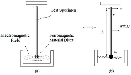
The specimen with magnetic discs attached at the tip is assumed to be fully clamped at one end and excited at the other end via an electromagnetic exciter in a test rig in accordance with the ASTM E756 standard [9] as illustrated in Fig. 1(a). Here, the beam can be
homogeneous or composite. In the proposed method, the additional inertia effect of the magnetic discs in Fig. 1(a) is modelled as a point mass m and the additional stiffness caused by the electromagnetic shaker is modelled as a spring with coefficient k as shown in Fig. 1(b). The electromagnetic spring is assumed to be linear based on experimental and theoretical examinations of a beam exposed to electromagnetic excitation in [22,32]. The equation of motion of the beam, based on Euler-Bernoulli beam theory, is as follows:
4 2 4 2 0 0 w w EI A x L x
t + = (1)where EI is the flexural rigidity, ρ is the density of the beam material and A is the cross-sectional area. The Boundary Conditions (BCs) at the clamped end are given as:
0 0 0, 0 x x w w x = = = = (2)
and the BCs at the free end of the beam supported by a spring and tip mass are given by:
2 2 2 2 0, 2 2 x L x L x L x L w w w EI EI m k w x = x x = t = = = = + (3)
7
Figure 1: (a) The beam in electromagnetic field affect and (b) the simplified model of the system.
Based on the assumption that the vibration has a harmonic form asw x t( , )=W x e( ) i t , the equation of motion becomes:
( )
2( )
0 0 iv A W x W x x L EI
− = (4)where the superscript iv refers to the fourth derivative with respect to x. The general solution of Eq. (4) is given as:
( )
1sin 2cos 3sinh 4coshW x =a
x+a
x+a
x+a
x (5) where 2 4 A EI
= (6)and a1, a2, a3 and a4 are some constants to be determined using the BCs. Applying the BCs, the characteristic equation of the system is obtained as [37]:
(
) (
)
3/ 4 1/ 4 1/ 4 1/ 4 1/ 4 1/ 4 1/ 4
cos cosh 1 cos sinh cosh sin 0
+ − − = (7)
where the non-dimensional terms are given as:
(
2)
3k m L
EI
8 4 2 AL EI = (9)
The roots of the characteristics equation yield values which, in turn, are used to
calculate the natural frequencies of the system using Eq. (9). It should be noted that when the coefficient is zero, i.e., when k = m = 0, the characteristic equation becomes:
(
)
3/ 4 1/ 4 1/ 4
cos cosh 1 0
+ = (10)
which is the characteristic equation for a beam without any modification. Setting the terms in the parenthesis in Eq. (10) to zero yields the non-trivial solution of a cantilever beam as:
1/ 4 1/ 4
cos cosh + =1 0 (11)
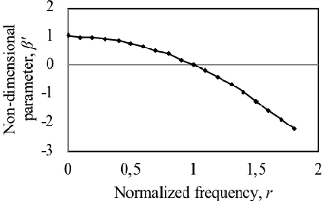
It should be stated here that the coefficient, which is a function of frequency, determines how the dynamics of the system change when mass and stiffness modifications are made at the tip of the beam. To illustrate the frequency-dependent characteristics of the coefficient for given m and k modifications, in Eq. (8) is normalised to obtain a non-dimensional parameter ' as: 2 3 ' EI 1 r kL
= = − (12) where , ' / ' r
k m
= = (13)Here, r is the normalised frequency and ' is the natural frequency of a single degree of freedom system defined by k and m. This non-dimensional parameter' can be examined to quantify the contributions of additional mass and/or spring to the change in a natural
9
The variation of ' is plotted as a function of normalised frequency r in Fig. 2. It is obvious that '= 1 when r = 0, quadratically decreasing to zero when r = 1 and then it becomes negative. A physical interpretation of this result is that ' is positive when the modification is stiffness dominated, thus, the corresponding natural frequencies of the system are expected to increase relative to those of the unmodified system. On the other hand, when
'
is negative, the overall modification is mass (inertia) dominated, which is causing the corresponding natural frequencies of the system to decrease relative to those of the
unmodified system. ' = 0 corresponds to a special case at a specific frequency = ' at which the system is not affected by the combination of mass and stiffness modifications at all.
Figure 2: The non-dimensional parameter as a function of normalized frequency r.'
The amount of changes, or errors, in the first four natural frequencies of a cantilever beam as a function of non-dimensional mass (i.e., the ratio of the tip mass to the mass of the beam) and stiffness (i.e., the ratio of the spring coefficient to the stiffness of the beam) are plotted in Fig. 3. The results suggest that the mass and stiffness modifications can lead to unacceptable levels of errors in natural frequencies. Furthermore, it is seen, as expected, that while the stiffness effect can be dominant for the lower modes, higher modes are affected
predominantly by the mass modification. The possibility of high levels of errors in natural frequencies naturally demands the removal of the adverse effects caused by the attached mass
10
and magnetic stiffening so as to estimate accurate material properties using the method in the ASTM E756 standard [9]. This is addressed in the next section.
(a) (b)
(c) (d)
Figure 3: The errors in (a) first, (b) second, (c) third and (d) fourth natural frequencies of cantilever beams as a function of mass and stiffness ratios.
3. Removal of the Adverse Loading Effects in the Oberst Beam Test Rig
As stated before, testing non-magnetic materials using the Oberst beam test rig with a magnetic exciter requires making mass modification to the test specimen and this
modification changes the natural frequencies, yielding an unreliable estimation of the material properties. Thus, the main objective of this work is to propose a method that can remove the adverse effects caused by such a modification. However, it is already known that the Oberst beam test rig with a magnetic exciter also introduces a magnetic stiffening effect [32].
11
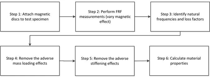
Therefore, for the complete removal of the adverse loading effects, it is also necessary to remove the adverse effects of magnetic stiffening. Accordingly, the method proposed here for the complete removal of the adverse loading effects is a two-stage process which comprises the removal of the mass loading effect in the first step followed by the removal of the magnetic stiffening effect, as suggested in [32], in the second stage. The associated steps in this process are outlined as a flowchart in Fig. 4.
The theoretical aspect of the removal of the adverse effects of the mass modification is presented in the next subsection, followed by numerical validation of the proposed method using the FE results of the homogeneous and layered beams. The experimental validation of the proposed method is carried out in the last subsection using ferromagnetic (steel) as well as non-magnetic beams.
Step 2: Perform FRF measurements (vary magnetic
effect)
Step 5: Remove the adverse stiffening effects
Step 3: Identify natural frequencies and loss factors
Step 4: Remove the adverse mass loading effects Step 1: Attach magnetic
discs to test specimen
Step 6: Calculate material properties
Figure 4: The outline of the proposed method to identify material properties of non-magnetic specimens.
3.1 Theory
In what follows, the theoretical foundation of the proposed method for the removal of only the mass loading effect is described. For brevity, the theory of the identification and removal of the adverse effect of the magnetic stiffness is not included here as it is already
12
available in [32]. However, removal of both mass and stiffness modifications are included in experimental applications of the proposed method in a forthcoming section.
Removing the adverse effects of undesirable mass loading from vibration measurements has been investigated extensively in the literature. However, the undesirable mass loading effects studied in the literature are generally considered to be caused by measurement transducersand such adverse effects are mostly removed from FRFs [38–40]. In the present study, we aim to determine the natural frequencies of the unmodified test specimen using the natural frequencies of the modified system so that it will be possible to estimate accurate material properties.
If one considers the case when a lumped mass is attached to the tip of a cantilever beam (without the magnetic spring effect), the characteristic equation given in Eq. (7) can be re-written as:
(
)
(
)
3/ 4 1/ 4 1/ 4 1/ 4 1/ 4 1/ 4 1/ 4
cos cosh 1 m cos sinh cosh sin 0
+ − − = (14) where 2 3 m m L EI
= − (15)The symbol
m here represents the situation when there is only an additional mass effect.
m in the characteristic equation can be expressed in terms of the parameter λ as follows:m m AL
= − (16)This equation allows the characteristic equation to be written as a function of λ, tip mass m and the mass of the test beam as:
13
(
1/ 4 1/ 4)
1/ 4(
1/ 4 1/ 4 1/ 4 1/ 4)
cos cosh 1 m cos sinh cosh sin 0
AL
+ + − = (17)
The eigenvalue λ satisfying Eq. (17) can now be referred to as the mass-affected eigenvalue, and hereupon, it is denoted with symbol λm. On the other hand, the corrected
eigenvalue (i.e., the eigenvalue of the characteristic equation of the cantilever beam without any adverse effect) satisfying Eq. (11) is denoted by λc. Accordingly, the ratio of λc to λm
given in Eq. (18) can be obtained purely based on theoretical grounds by numerically solving Eqs. (11) and (17).
c c m
= (18)Once the eigenvalue ratio in Eq. (18) is known for a given tip mass and noting the relationship between the eigenvalue and the natural frequency:
1/ 2 4 1 2 c c EI f AL = (19)
the corresponding natural frequencies of the test beam without the adverse effects of the tip mass (fc) can be calculated using the measured natural frequencies with the tip mass (fm) as
follows:
c m c
f = f
(20)The so-called Frequency Correction Factors (FCFs) for individual modes, c , are calculated as a function of the ratio of the tip mass to the mass of the cantilever beam and results are presented in Fig. 5 for the first four bending modes. It can immediately be seen that the lower modes are more strongly affected by the tip mass modification. It can also be seen that larger the attached mass, the higher the adverse effect, hence the FCFs. It is worth stating
14
that the theoretical results presented in Fig. 5 allow one to determine the FCFs just by knowing the attached mass and the total mass of the test beam. Although not included here for brevity, FCFs for modes higher than the fourth mode can also be obtained by using the same procedure described above.
Figure 5: Frequency correction factors as a function of the non-dimensional mass ratio for the first four modes of cantilever beams.
After the correct natural frequencies of test samples are obtained, their material properties can be determined with higher accuracy. The Young’s modulus of a self-supporting material for a given mode is calculated as [9]:
4 2 2 2 12 n n L f E H C = (21)
where ρ is the density [kg/m3], L is the length of the beam [m], f
n is the nth corrected natural
frequency [Hz], H is the thickness of the specimen [m], and Cn refers to the coefficient for the
cantilever beam. The loss factor of a self-supporting material can be obtained via analysing the measured FRFs. The proposed method can also be applied to non-self-supporting materials by using the layered configurations in OBM [9]. For this purpose, the measured natural frequencies of the base and layered beams are corrected first, then the corrected
15
natural frequencies are used to determine the material properties according to the formulations presented in [9] as described in the next section.
3.2 Numerical Validation
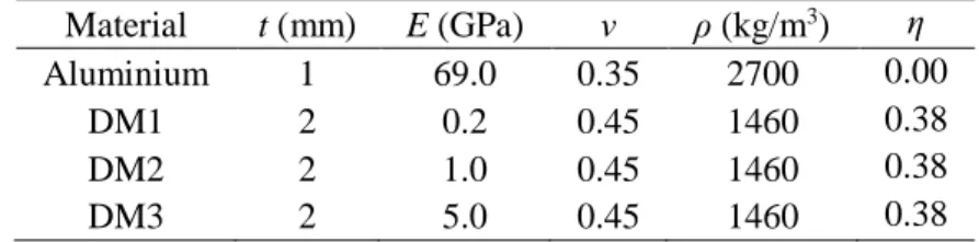
This subsection aims to demonstrate the validity of the proposed method for the removal of the adverse effect of the tip mass via numerical simulations based on the FE approach. The removal of the adverse effects of both the tip mass and the stiffness of the electromagnetic exciter are addressed in the next section using experimental data. Here, a homogeneous and three free-layered beams (named as FL1, FL2 and FL3) are investigated. The homogenous beam is made of aluminium and the individual free-layered (Oberst) beams are formed using the same aluminium base and three different damping materials. The properties of the base and damping layers are listed in Table 1 where the symbols ν and η represent the Poisson’s ratio and the loss factor of the materials, respectively.
Table 1: The properties of the base and damping layers for the beams used in numerical simulations (Length: 220 mm, width: 10 mm). Material t (mm) E (GPa) ν ρ (kg/m3) η Aluminium 1 69.0 0.35 2700 0.00 DM1 2 0.2 0.45 1460 0.38 DM2 2 1.0 0.45 1460 0.38 DM3 2 5.0 0.45 1460 0.38
Sufficient numbers of three-dimensional 20-noded solid elements, (C3D20R) in
ABAQUS [41], are used for modelling the homogenous and layered beams. In the FE model, the tip mass is modelled as a lumped point-mass with a value of 0.34 g at the tip of the beam. Natural frequencies of the beams are predicted for the two cases corresponding to the
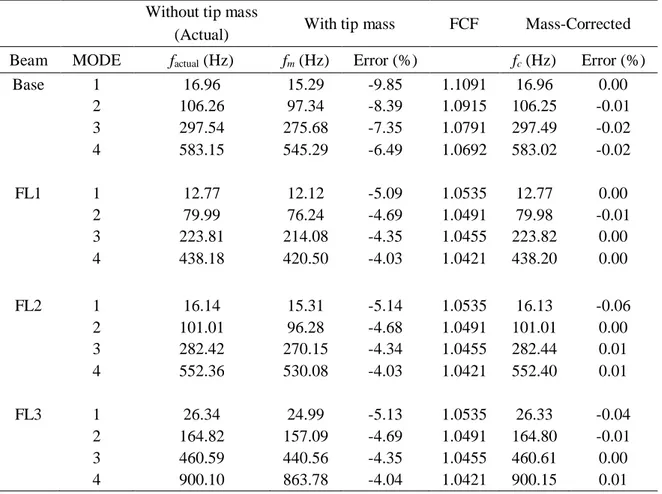
situations with and without the tip mass. Then, the natural frequencies of the beams without the tip mass (referred to as mass-corrected frequencies) are calculated using the FCFs and the natural frequencies of the beams with the tip mass. The results are listed in Table 2. It can be
16
clearly seen that a tip mass of less than even half a gram can produce a very significant amount of error in natural frequencies if the tip mass is ignored in the model. However, it can also be seen that the proposed method is successfully estimating the correct natural
frequencies of the bare and layered beams without the tip mass, thus, reducing the errors in the natural frequencies to almost a negligible level.
Table 2: Comparisons of the actual, estimated (with the tip mass) and the corrected natural frequencies, and the associated errors.
Without tip mass
With tip mass FCF Mass-Corrected (Actual)
Beam MODE factual (Hz) fm (Hz) Error (%) fc (Hz) Error (%)
Base 1 16.96 15.29 -9.85 1.1091 16.96 0.00 2 106.26 97.34 -8.39 1.0915 106.25 -0.01 3 297.54 275.68 -7.35 1.0791 297.49 -0.02 4 583.15 545.29 -6.49 1.0692 583.02 -0.02 FL1 1 12.77 12.12 -5.09 1.0535 12.77 0.00 2 79.99 76.24 -4.69 1.0491 79.98 -0.01 3 223.81 214.08 -4.35 1.0455 223.82 0.00 4 438.18 420.50 -4.03 1.0421 438.20 0.00 FL2 1 16.14 15.31 -5.14 1.0535 16.13 -0.06 2 101.01 96.28 -4.68 1.0491 101.01 0.00 3 282.42 270.15 -4.34 1.0455 282.44 0.01 4 552.36 530.08 -4.03 1.0421 552.40 0.01 FL3 1 26.34 24.99 -5.13 1.0535 26.33 -0.04 2 164.82 157.09 -4.69 1.0491 164.80 -0.01 3 460.59 440.56 -4.35 1.0455 460.61 0.00 4 900.10 863.78 -4.04 1.0421 900.15 0.01
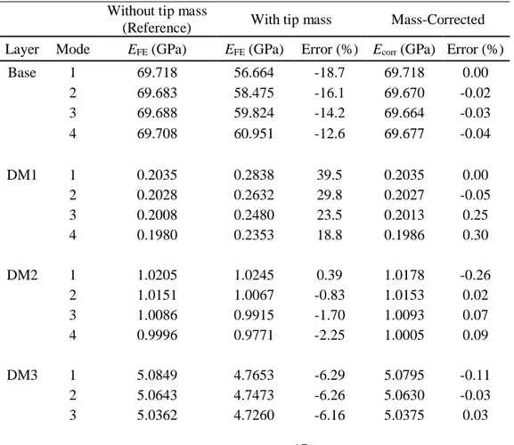
In accordance with OBM, the Young’s moduli of the base beam and the damping layers are calculated using the uncorrected and corrected natural frequencies listed in Table 2. The results are presented in Table 3. It is seen that, for the base beam (i.e., for self-supporting materials), the proposed method removes almost all of the adverse effects of the additional mass, leading to identify the correct material properties. Inspection of the identified Young’s
17
moduli of the individual damping layers before and after the mass-corrections in Table 3 reveals that: (i) the tip mass can cause very large amount of errors in estimated material properties if its adverse effects are not removed, (ii) the proposed method successfully eliminates the errors caused by the tip mass in all cases, reducing the errors in E to a level of about 0.3 % even in the worst case. It should be noted that if the adverse effects of the added mass are not removed, the same amount tip mass can result in very different levels of errors in identified E of the damping layer depending on the properties of the Oberst beam (e.g., on average, more than 25% for DM1, about -1% for DM2 and about -6% for DM3). These errors depend on how the natural frequencies of the Oberst beam are changing relative to those of the base beam. The highest errors are obtained when the natural frequencies of the Oberst beam are significantly lower than those of the base beam due to the inertia dominated effect of the free layer.
Table 3: Comparisons of the actual (reference), estimated (with the tip mass) and the corrected Young’s moduli, and the associated errors.
Without tip mass
(Reference) With tip mass Mass-Corrected Layer Mode EFE (GPa) EFE (GPa) Error (%) Ecorr (GPa) Error (%)
Base 1 69.718 56.664 -18.7 69.718 0.00 2 69.683 58.475 -16.1 69.670 -0.02 3 69.688 59.824 -14.2 69.664 -0.03 4 69.708 60.951 -12.6 69.677 -0.04 DM1 1 0.2035 0.2838 39.5 0.2035 0.00 2 0.2028 0.2632 29.8 0.2027 -0.05 3 0.2008 0.2480 23.5 0.2013 0.25 4 0.1980 0.2353 18.8 0.1986 0.30 DM2 1 1.0205 1.0245 0.39 1.0178 -0.26 2 1.0151 1.0067 -0.83 1.0153 0.02 3 1.0086 0.9915 -1.70 1.0093 0.07 4 0.9996 0.9771 -2.25 1.0005 0.09 DM3 1 5.0849 4.7653 -6.29 5.0795 -0.11 2 5.0643 4.7473 -6.26 5.0630 -0.03 3 5.0362 4.7260 -6.16 5.0375 0.03
18
4 4.9969 4.6981 -5.98 4.9986 0.03
The Young’s moduli of the bare beam and the damping layer as well as the loss factors of the Oberst beam are required for the determination of the loss factor of the damping layer. The modal loss factors of the beams with and without the tip mass are estimated using the modal strain energy method [42]. Although the numerical results are not presented here, for brevity, it is found that adding tip mass as a lumped point-mass to the FE models did not cause any change in modal loss factors of homogenous and layered (Oberst) beams. This is an expected result since a lumped point-mass can neither stores strain energy nor dissipates energy. It is worth stating here that this issue is revisited in the discussion section where the tip mass is considered as a 3D object in the FE model. As a summary, the results of the FE simulations suggest that the method proposed for removing the adverse effects of mass modification can be very effective for determining the correct modal parameters of the test specimens.
3.3 Experimental Validation
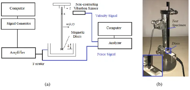
An experimental setup is designed for the experimental validation and application of the proposed method for the removal of the adverse effects of the tip mass and the magnetic stiffness. In the experimental study, a signal is generated and amplified using a power amplifier (TWS 18) and sent through a T-router to the magnetic exciter. The other end of the T-router is connected to an analyser, as shown in Fig. 6(a). A laser scanning head (Polytech PSV 400) is used to measure the response of the beam exposed to the electromagnetic excitation and the response signal is also sent to the analyser to perform FRF measurements. The measurements are performed within 0-2000 Hz. An image of the Oberst beam test rig, including the test specimen with ferromagnetic discs, is also presented in Fig. 6(b). It is worth mentioning here that the length of the segment of the beam exposed into the magnetic exciter
19
slot (δ), shown in Fig. 6(a), is the main parameter controlling the magnetic stiffening effect and, when δ is constant, it is acting as a linear spring [22,32].
(a) (b)
Figure 6: (a) Schematic of the experimental setup and (b) the Oberst beam test rig including the test specimen with ferromagnetic discs.
The next two subsections present the results of the applications of the proposed method to beams made of different materials. The homogeneous beam is made of steel, which, in fact, does not require the attachment of additional ferromagnetic material to the tip of the beam for magnetic excitation. However, a homogeneous steel beam is deliberately used here so as to be able to determine the actual natural frequencies of the system without the tip mass
experimentally so that the performance of the method can be assessed using the “actual” natural frequencies and loss factors as reference values. Then, the proposed method is used for a beam made of non-magnetic material, which represents a real situation demanding tip mass modification in order to estimate modal properties for material characterisation.
3.3.1 Validation using a homogeneous beam made of ferromagnetic material
A steel beam specimen with the properties t = 1 mm, w = 10 mm, L = 220 mm, ρsteel = 7581 kg/m3 is tested using the Oberst beam test rig. FRF measurements are performed without the tip mass first, and then with a total of 0.34 g tip mass (two small discs made of
20
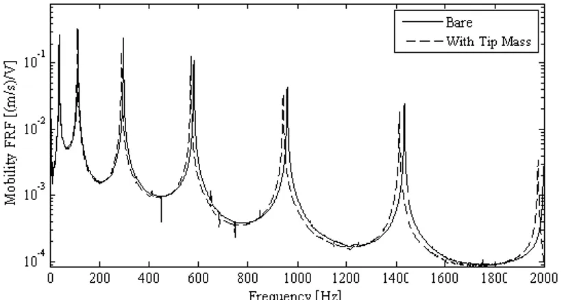
steel) in order to quantify the effects of the attached mass. The discs are glued to the tip of the beam on both sides such that the mass centres of the discs coincide with the tip of the beam. It should be noted, however, that this resulted in a portion of the small discs extending beyond the tip of the beam. Sample FRFs presented in Fig. 7 clearly demonstrate the natural
frequency shifts caused by the attachment of the ferromagnetic discs to the tip of the beam. It is also seen in Fig. 7 that the sharpness of the peaks of the FRFs around each mode remains almost the same, suggesting that the change of modal damping values due to the added tip mass is either very small or negligible. The experiments are performed for different values of gap parameter, δ, with an increment of 1 mm, in order to estimate the magnetic stiffening effect of the electromagnetic exciter. However, the maximum possible value of δ, dictated by the magnetic exciter used in the tests, was 5 mm.
Figure 7: Two measured FRFs of the steel beam with (dashed curve) and without (continuous curve) tip mass modification.
The tests described so far provided experimentally identified natural frequencies for the steel beam with and without the tip mass for different values of gap parameter δ. The natural frequencies corresponding to the beam with tip mass are corrected using the FCFs in order to estimate the natural frequencies of the system without the tip mass. The FCFs are obtained to be 1.0407 for the first mode, 1.0377 for the second mode, 1.0353 for the third mode and 1.0334 for the fourth mode. The measured natural frequencies of the beam with and without
21
the tip mass, and the mass-corrected natural frequencies are plotted as a function of the gap parameter in Fig. 8. (a) 15 18 21 24 27 30 0 2 4 6 f1 [Hz ] Gap Parameter, δ [mm] (b) 102 104 106 108 110 0 2 4 6 f2 [H z] Gap Parameter, δ [mm] (c) 285 288 291 294 297 300 0 2 4 6 f3 [H z] Gap Parameter, δ [mm] (d) 565 570 575 580 585 590 0 2 4 6 f4 [H z] Gap Parameter, δ [mm]
Figure 8: Experimentally obtained natural frequencies of a steel specimen with tip mass (▲), without tip mass (♦) and mass-corrected natural frequencies (■) for (a) first, (b) second, (c) third and (d) fourth modes.
The inspection of the results presented in Fig. 8 demands assessing the results in two frequency ranges; one for the higher modes, and the other for the lower modes (first mode in this case). As far as the higher modes are concerned, it can be seen that the natural frequencies of the beam with the tip mass are always lower than those without the tip mass, implying that mass modification is dominating at these frequencies. Also, the results clearly show that the natural frequencies of the beam with and without the tip mass, even for a quantity of tip mass which is less than half a gram, are significantly different from each other, suggesting that
22
even such a small amount of tip mass should not be ignored in practice. Nevertheless, it is obvious that the application of the proposed method successfully estimates the natural frequencies of the beam without the tip mass using the natural frequencies of the beam with the tip mass and the calculated FCFs. As seen in Fig. 8, the corrected natural frequencies are very close to the correct ones for the second, third and fourth modes. On the other hand, the results for the first mode may appear somewhat unexpected at first sight in the sense that in spite of the tip mass modification, the natural frequency of the first mode hardly changes for the lower values of the gap parameter δ and then starts to increase for higher values of δ. This is actually not surprising at all; the results are simply demonstrating that around the first natural frequency, the net effect of the tip mass and magnetic stiffness modification is mainly stiffness dominated, causing the natural frequency to increase as the gap parameter is
increased. However, it can also be seen that the effects of mass and stiffness modifications approximately cancel each other out when δ is about 1.0 mm, yielding almost identical natural frequencies for the beams with and without the tip mass.
As the results in Fig. 8 demonstrate, the removal of the adverse effect of the tip mass alone may not be sufficient, especially for the lower mode(s) (in this case the first mode), in order to predict the natural frequencies of the unmodified system with acceptable accuracy. Thus, the removal of the adverse effect of the magnetic stiffness is also needed. This is addressed using the extrapolation method recommended in [32], yielding the final, corrected natural frequencies of the system as listed in Table 4. A third order extrapolation is employed here for removing the adverse magnetic stiffening effect. However, it is worth stating here that the order of the extrapolation does not significantly change the estimated natural
frequencies. All in all, as can be seen from Table 4, the corrected natural frequencies (cleared from both of the adverse effects), fsc, are estimated with an error of less than half a percent for
23
error being higher for the first mode is actually expected since the first mode is known to be adversely affected by other factors including air resistance. In fact, the use of the experimental results for the first mode is not recommended in practice, especially for sandwich beams for material characterisation [9]. Accordingly, although the results for the first mode are included in this paper, we do not recommend the use of the data for the first mode for the
characterisation of materials if the test system introduces both mass and stiffness modifications to the test specimen.
Table 4: Natural frequencies of a steel beam before and after the removal of the adverse effects of tip mass and magnetic stiffening.
Experimental (without tip mass - actual)
Experimental
(with tip mass) Corrected Mode factual (Hz) fm (Hz) Error (%) fsc (Hz) Error (%)
1 17.01 16.85 -0.94 17.54 3.12
2 106.21 102.66 -3.34 106.53 0.30 3 297.49 288.22 -3.12 298.39 0.30 4 583.32 566.26 -2.92 585.16 0.32
The benefits of the removal of the adverse effects of mass and stiffness modifications on material characterisation are also investigated. Accordingly, the Young’s moduli of the steel beam specimen are calculated using Eq. (21) by using the correct natural frequencies
(experimental ones without the tip mass), natural frequencies with the tip mass and magnetic spring, and by using the corrected natural frequencies via the procedure proposed in this paper. The results presented in Table 5 confirm that the errors in the estimated Young’s moduli can be reduced by almost an order of magnitude for higher modes, although the error reduction in the estimated material properties corresponding to the first mode is somewhat higher. The reason for this relatively lower accuracy for the first mode is believed to be mainly due to the portion of the small discs made of ferromagnetic material extending beyond the tip of the beam as well as other non-linear effects including the air resistance.
24
Table 5: Comparisons of the estimated Young’s moduli of a steel beam with its actual values. Experimental
(without tip mass - actual)
Experimental
(with tip mass) Corrected
Mode Eactual (GPa) Emeas (GPa) Error (%) Ecorr (GPa) Error (%)
1 196.91 193.22 -1.9 209.37 6.3
2 195.47 182.62 -6.6 196.65 0.6
3 195.60 183.60 -6.1 196.79 0.6
4 195.84 184.55 -5.8 197.08 0.6
The loss factors of the specimen are also determined using the measured FRFs with and without magnetic discs. The line-fit method [43] is used for this purpose and the results are listed in Table 6. It is known that the elastic and damping properties of steel are not expected to change with frequency in the frequency range of interest here. The identified loss factors are found to be about 0.2% or lower and these results in Table 6 are in good agreement with the literature [9]. It is seen that the gap parameter and mass modification have a negligible effect on modal loss factors (the difference being less than 0.06%), circumventing the need for any correction of modal loss factors. As stated before, the use of the first mode is not recommended in the standard as it is difficult to estimate reliable material properties for this mode. Accordingly, the loss factors for the first mode are not included in Table 6.
Table 6: The experimentally determined modal loss factors of the steel beam with and without tip mass for different configurations of the gap parameter.
Without Tip Mass
δ (mm) 1 2 3 4 5 Average
MODE η (%)
2 0.22 0.21 0.19 0.24 0.25 0.22 3 0.16 0.16 0.16 0.17 0.16 0.16 4 0.14 0.14 0.15 0.13 0.14 0.14
With Tip Mass
δ (mm) 1 2 3 4 5 Average
MODE η (%)
2 0.24 0.24 0.22 0.22 0.23 0.23 3 0.15 0.16 0.15 0.16 0.16 0.15 4 0.13 0.13 0.13 0.13 0.13 0.13
25
3.3.2 Application to a beam made of non-magnetic material
This section presents the application of the proposed method to a non-magnetic (carbon-fibre reinforced composite) beam specimen whose properties cannot be measured via the Oberst beam test rig with an electromagnetic exciter without the use of ferromagnetic discs. The active length of the beam used here is L = 220 mm, the beam thickness is 0.7 mm and the overall density of the beam is ρcomp = 1202.6 kg/m3. One can easily infer that the adverse effects of the added mass will be stronger in this case due to the density of the beam being lower than that of the steel beam used in the previous tests. Two ferromagnetic discs (with a total mass 0.34 g again) are glued at the tip of the non-magnetic beam and the measurements are carried out for different gap parameters as it is done for the steel beam. The FCFs are calculated (using the ratio of the tip mass to the mass of the beam) for the beam and found to be 1.3216 for the first mode, 1.2011 for the second mode, 1.1471 for the third mode and 1.1147 for the fourth mode. The high values of these FCFs immediately reveal that the added tip mass affects the natural frequencies quite strongly.
The measured natural frequencies of the non-magnetic beam with the tip mass as well as the mass-corrected natural frequencies are presented in Fig. 9. As anticipated, the difference between the corrected and the measured natural frequencies are much greater than the corresponding results for the steel beam due to the density of the non-magnetic beam being much lower than that of the steel beam. After the removal of the effect of the tip mass, the effect of the magnetic stiffening effect is also removed by interpolating the mass-corrected natural frequencies in Fig. 9, i.e., estimating the natural frequencies corresponding to δ = 0.
26 (a) 0 10 20 30 40 0 2 4 6 f1 [H z] Gap Parameter, δ [mm] (b) 50 60 70 80 90 0 2 4 6 f2 [Hz ] Gap Parameter, δ [mm] (c) 190 200 210 220 230 0 2 4 6 f3 [H z] Gap Parameter, δ [mm] (d) 380 400 420 440 460 0 2 4 6 f4 [H z] Gap Parameter, δ [mm]
Figure 9: Experimentally obtained natural frequencies of a non-magnetic specimen (▲) and mass-corrected natural frequencies (■), for (a) first, (b) second, (c) third and (d) fourth modes.
Table 7: Natural frequencies of a non-magnetic beam before and after the removal of mass and magnetic stiffening effects.
Experimental
(with tip mass) Corrected MODE fm (Hz) Emeas (GPa) fsc (Hz) Ecorr (GPa)
1 13.32 39.1 17.60 68.3 2 68.20 26.1 81.90 37.6 3 196.55 27.6 225.47 36.4 4 396.77 29.3 442.27 36.4
The final values of the corrected natural frequencies together with the measured ones as well as the estimated Young’s moduli of the carbon-fibre reinforced beam using the measured and corrected natural frequencies are listed in Table 7. It is obvious that while the discs made of ferromagnetic material make it possible to excite the system and allow the identification of the natural frequencies, the added mass can change (reduce in this case) the natural
27
to these results, it can be said that without the removal operation of the adverse effects, the estimated Young’s moduli of the specimen would have been about 25% lower than the actual value. It should be stressed, once again, that although the Young’s modulus corresponding to the first mode is calculated and listed in Table 7, it is evident that the result for the first mode is not reliable. Hence, it should be ignored in practice.
The experimentally determined modal loss factors of the carbon-fibre reinforced beam with different gap parameter values are listed in Table 8. These results reveal, once again, that the loss factors do not significantly vary with the gap parameter. The experimental and
numerical results confirm that the proposed method for the removal of the adverse effects of mass modification, combined with the subsequent removal of the electromagnetic stiffening effects, is very effective.
Table 8: The experimentally determined modal loss factors of the carbon-fibre reinforced beam with the tip mass.
δ (mm) 1 2 3 4 5 Average MODE η (%) 2 0.33 0.32 0.29 0.33 0.32 0.32 3 0.20 0.21 0.22 0.19 0.20 0.20 4 0.24 0.24 0.24 0.24 0.24 0.24 4. Discussion
In the proposed method, the attached mass (small discs) at the tip of the beam is modelled as a lumped point-mass. This means that the rotational inertia of the discs as well as the strain energy carried by the discs during deformation are implicitly assumed to be negligible. Moreover, it is assumed that the attached mass is positioned exactly at the tip of the beam, ignoring any positioning error. Here, using a FE model of the carbon-fibre reinforced beam (with 20-noded solid elements), some FE simulations are performed to assess the validity or implications of these assumptions. In the simulations, it is assumed that the discs are made of
28
steel, with material properties Edisc =205 GPa, ρdisc = 8750 kg/m3, νdisc = 0.3 and ηdisc = 0.0%, and the homogeneous beam is made of a non-magnetic material with material properties Ecf = 37 GPa, ρcf = 1202.6 kg/m3, νcf = 0.35 and ηcf = 0.25%. This resulted in a mass ratio (discs masses to beam mass) being equal to about 0.18. The estimated natural frequencies using the FE model, their corrected values using the proposed method which does not take the
rotational inertia effects into account and the corresponding errors are listed in Table 9. It can be seen that the effects of the discs’ rotational inertia on the natural frequency of the structure is almost negligible (less than 0.3%) for a mass ratio of 0.18 for the first four modes. Further analyses are carried out by doubling the mass at the tip and the error due to ignoring the effects of rotational inertia is found to be less than 0.5%, even for a mass ratio of 0.36.
Table 9: The effects of rotary inertia of the discs on the natural frequencies of the test specimen. Without discs
(Actual)
With discs
(3D FE elements) Mass-Corrected MODE factual (Hz) fFE (Hz) fcorr (Hz) Error (%)
1 13.02 9.89 13.00 -0.15
2 81.56 67.97 81.50 -0.07
3 228.39 198.95 228.04 -0.15 4 447.71 400.76 446.49 -0.27
The effect of the discs on modal damping values of the system is also investigated. During this investigation, the loss factors for the beam and disc materials are set to ηcf = 0.25% and ηdisc = 0.0%, respectively. The modal loss factors for the beam with and without the discs are predicted via the modal strain energy method using the FE models. The modal loss factors for the beam with and without the discs are found to be almost identical, i.e., 0.25%. This means that strain energy stored by the discs at the tip of the cantilever beam is extremely small compared to that of the beam itself, hence, the effect of the tip mass on modal damping levels can safely be considered negligible as verified experimentally before.
29
As stated, the proposed method in this paper assumes that the ferromagnetic discs are placed exactly at the tip of the beam. However, this may not be possible in practice. Possible errors that might be caused by the imprecise positioning of the discs are estimated using the FE model for the carbon-fibre reinforced beam again. Natural frequencies of the system are predicted when the discs are placed at slightly different positions around the tip of the beam and the corrected natural frequencies are determined using the proposed method. Then, the errors in the natural frequencies due to the inaccurate positioning of the discs are determined and listed in Table 10. It can be seen that accurate positioning of the discs at the tip of the beam is important; a positioning error of around 1mm can lead to an error of around 0.8% in corrected natural frequencies for the first four modes.
Table 10: Errors in corrected natural frequencies caused by misplacement of the tip mass. Error in position of
the tip mass (mm) 0.5 1 1.5
Mode Error (%)
1 0.56 0.70 0.84
2 0.48 0.80 1.12
3 0.45 0.83 1.20
4 0.44 0.85 1.26
Positioning the discs at the tip of a beam has some advantages. For example, doing so guarantees that all the bending modes within a frequency range of interest can be excited by the electromagnetic exciter. Also, the strain energy carried by the added mass is automatically minimised when the mass is positioned at the tip of the beam. Nevertheless, the method proposed here can be extended for an arbitrary exciter position. The eigenvalue problem of a beam carrying a point mass at an arbitrary position has already been studied in the literature [44–46]. For extending the presented method here for an arbitrary disc position, only the characteristic equation in Eq. (17) should be replaced for the new case. This topic, as well as
30
testing different types of beam specimens including layered beams, is considered to be an area for future research.
5. Conclusions
The Oberst beam test rig with an electromagnetic exciter is widely used for identifying frequency-depended mechanical properties of materials. Although the specimens made of ferromagnetic materials can safely be excited and tested using this test rig, testing
non-magnetic materials using a test rig with an electronon-magnetic exciter is not possible unless some magnetic particles or ferromagnetic discs are attached to the tip of the test beam. However, attaching these particles or discs introduces undesirable mass modification combined with an electromagnetic stiffness effect to the system and these adverse effects can significantly reduce the accuracy of the estimated material properties. In this paper, first the consequences of such a modification are investigated and it is demonstrated that the natural frequencies of the beam with a relatively small amount of tip mass exposed to electromagnetic excitation are significantly affected. It is also shown that, relative to the unmodified system, the natural frequencies of the lower modes of the modified system can increase due to the stiffness-dominated effect, while those of the higher modes decrease due to the mass-stiffness-dominated effect. Then, a method is proposed for eliminating the adverse effects of the tip mass modification to the test specimen, which also allows the subsequent removal of the electromagnetic stiffening effects produced by the electromagnetic exciter.
The validation of the proposed method is carried out using numerical simulations as well as experimental results. FE simulations confirmed that the proposed approach is very effective for removing the adverse effects of tip mass modification from the natural
frequencies of homogeneous and Oberst beams subjected to such modifications, leading to more reliable identification of material properties. The experimental study comprised tests on
31
beam specimens made of steel as well as non-magnetic material. The experimental results also confirmed that the proposed method for the removal of the adverse effects of mass
modification, combined with the subsequent removal of the electromagnetic stiffening effects, is very effective, making it possible to determine the Young’s moduli of non-magnetic
materials with high accuracy. The findings of the experimental and numerical studies show that the magnetic stiffness and mass modification have negligible effects on modal loss
factors of test specimens, hence, there is no need for correction of loss factors when a tip mass is used. The proposed method appears to be very promising for the accurate identification of material properties of non-magnetic materials using the Oberst Beam Method.
32
6. REFERENCES
[1] E. Bodros, I. Pillin, N. Montrelay, C. Baley, Could biopolymers reinforced by
randomly scattered flax fibre be used in structural applications?, Compos. Sci. Technol. 67 (2007) 462–470. doi:10.1016/j.compscitech.2006.08.024.
[2] G. Genc, H. Koruk, Identification of the dynamic characteristics of luffa fiber reinforced bio-composite plates, BioResources. 12 (2017) 5358–5368.
doi:10.15376/biores.12.3.5358-5368.
[3] A. Borri, M. Corradi, E. Speranzini, Reinforcement of wood with natural fibers, Compos. Part B Eng. 53 (2013) 1–8. doi:10.1016/j.compositesb.2013.04.039. [4] M. Mastali, A. Dalvand, A.R. Sattarifard, The impact resistance and mechanical
properties of reinforced self-compacting concrete with recycled glass fibre reinforced polymers, J. Clean. Prod. 124 (2016) 312–324. doi:10.1016/j.jclepro.2016.02.148. [5] W.K. Goertzen, M.R. Kessler, Dynamic mechanical analysis of carbon/epoxy
composites for structural pipeline repair, Compos. Part B Eng. 38 (2007) 1–9. doi:10.1016/j.compositesb.2006.06.002.
[6] N. Saba, M. Jawaid, O.Y. Alothman, M.T. Paridah, A review on dynamic mechanical properties of natural fibre reinforced polymer composites, Constr. Build. Mater. 106 (2016) 149–159. doi:10.1016/j.conbuildmat.2015.12.075.
[7] K.P. Menard, Dynamic mechanical analysis: A practical introduction, CRC Press, 2008.
[8] H. Oberst, K. Frankenfeld, Über die Dämpfung der Biegeschwingungen dünner Bleche durch fest haftende Beläge (On damping of the bending vibrations of thin sheet metal by means of firmly adhering coatings), Acta Acust. United with Acust. 2 (1952) 181– 194.
[9] ASTM E 756 - 05, Standard Test Method for Measuring Vibration-Damping Properties of Materials, 2005.
[10] SAE J1637, Laboratory Measurement of the Composite Vibration Damping Properties of Materials on a Supporting Steel Bar, 1993.
[11] A.D. Nashif, D.I.G. Jones, J.P. Henderson, Vibration Damping, John Wiley and Sons, 1985.
[12] H.Y. Yen, M.H. Herman Shen, Passive vibration suppression of beams and blades using magnetomechanical coating, J. Sound Vib. 245 (2001) 701–714.
doi:10.1006/jsvi.2001.3561.
[13] J.M. Berthelot, M. Assarar, Y. Sefrani, A. El Mahi, Damping analysis of composite materials and structures, Compos. Struct. 85 (2008) 189–204.
doi:10.1016/j.compstruct.2007.10.024.
[14] K.S. Ledi, M. Hamdaoui, G. Robin, E.M. Daya, An identification method for
frequency dependent material properties of viscoelastic sandwich structures, J. Sound Vib. 428 (2018) 13–25. doi:10.1016/j.jsv.2018.04.031.
33
[15] L. Irazu, M.J. Elejabarrieta, Analysis and numerical modelling of eddy current damper for vibration problems, J. Sound Vib. 426 (2018) 75–89.
doi:10.1016/j.jsv.2018.03.033.
[16] K.Y. Sanliturk, H. Koruk, Development and validation of a composite finite element with damping capability, Compos. Struct. 97 (2013) 136–146.
doi:10.1016/j.compstruct.2012.10.020.
[17] K.Y. Sanliturk, H. Koruk, A new triangular composite shell element with damping capability, Compos. Struct. 118 (2014) 322–327.
doi:10.1016/j.compstruct.2014.07.053.
[18] F.L. de Carvalho Moura, T.S. Ferreira, R.G. Costa, C.K. Takemori, E. Baars,
Development and Validation of Numerical Model for Standardized Oberst Beam Test (ASTM E 756-98), in: SAE Int., 2014. doi:10.4271/2014-36-0796.
[19] P.A. Prasob, M. Sasikumar, Static and dynamic behavior of jute/epoxy composites with ZnO and TiO2 fillers at different temperature conditions, Polym. Test. 69 (2018) 52– 62. doi:10.1016/j.polymertesting.2018.04.040.
[20] A. Fasana, A. Ferraris, A.G. Airale, D. Berti Polato, M. Carello, Oberst and aging tests of damped CFRP materials: New fitting procedure and experimental results, Compos. Part B Eng. 148 (2018) 104–113. doi:10.1016/j.compositesb.2018.04.046.
[21] H. Koruk, K.Y. Sanliturk, On Measuring Dynamic Properties of Damping Materials Using Oberst Beam Method, in: ASME 2010 10th Bienn. Conf. Eng. Syst. Des. Anal. Vol. 2, 2010: pp. 127–134. doi:10.1115/ESDA2010-24452.
[22] H. Koruk, K.Y. Sanliturk, Modelling electromagnetic effect of the non-contact excitation system in Oberst beam method, in: 42nd Int. Congr. Expo. Noise Control Eng. 2013, INTER-NOISE 2013 Noise Control Qual. Life, 2013.
[23] M.S. Ozer, H. Koruk, K.Y. Sanliturk, Characterization of viscoelastic materials using free-layered and sandwiched samples: Assessment and recommendations, Acta Phys. Pol. A. 127 (2015) 1251–1254. doi:10.12693/APhysPolA.127.1251.
[24] L.R. Carvalho, E.M. Coraça, Exploring Oberst Beam Standard Method for Viscoelastic Materials to Increase Test Confidence and Applicability, in: SAE INTERNATIONAL, Sao Paulo, 2017. doi:10.4271/2017-36-0179.
[25] P.J. Torvik, On estimating system damping from frequency response bandwidths, J. Sound Vib. 330 (2011) 6088–6097. doi:10.1016/j.jsv.2011.06.027.
[26] J.-L. Wojtowicki, L. Jaouen, R. Panneton, New approach for the measurement of damping properties of materials using the Oberst beam, Rev. Sci. Instrum. 75 (2004) 2569–2574. doi:10.1063/1.1777382.
[27] Y. Liao, V. Wells, Estimation of complex Young’s modulus of non-stiff materials using a modified Oberst beam technique, J. Sound Vib. 316 (2008) 87–100. doi:10.1016/j.jsv.2008.02.028.
[28] F. Cortés, M.J. Elejabarrieta, Viscoelastic materials characterisation using the seismic response, Mater. Des. 28 (2007) 2054–2062. doi:10.1016/j.matdes.2006.05.032.
34
[29] G.L. Ghiringhelli, M. Terraneo, Analytically driven experimental characterisation of damping in viscoelastic materials, Aerosp. Sci. Technol. 40 (2015) 75–85.
doi:10.1016/j.ast.2014.10.011.
[30] S.Y. Kim, D.H. Lee, Identification of fractional-derivative-model parameters of viscoelastic materials from measured FRFs, J. Sound Vib. 324 (2009) 570–586. doi:10.1016/j.jsv.2009.02.040.
[31] A. Renault, L. Jaouen, F. Sgard, Characterization of elastic parameters of acoustical porous materials from beam bending vibrations, J. Sound Vib. 330 (2011) 1950–1963. doi:10.1016/j.jsv.2010.11.013.
[32] H. Koruk, K.Y. Sanliturk, Identification and removal of adverse effects of non-contact electromagnetic excitation in Oberst Beam Test Method, Mech. Syst. Signal Process. 30 (2012) 274–295. doi:10.1016/j.ymssp.2012.02.003.
[33] C.C. Chen, M.K. Yeh, Parametric instability of a beam under electromagnetic excitation, J. Sound Vib. 240 (2001) 747–764. doi:10.1006/jsvi.2000.3255.
[34] R.-F. Fung, Y.-T. Liu, C.-C. Wang, Dynamic model of an electromagnetic actuator for vibration control of a cantilever beam with a tip mass, J. Sound Vib. 288 (2005) 957– 980. doi:10.1016/j.jsv.2005.01.046.
[35] E. Schmidt, W. Paradeiser, F. Dohnal, H. Ecker, Design of an electromagnetic actuator for parametric stiffness excitation, COMPEL - Int. J. Comput. Math. Electr. Electron. Eng. 26 (2007) 800–813. doi:10.1108/03321640710751235.
[36] C.C. Fan, M.C. Pan, Fluid-induced instability elimination of rotor-bearing system with an electromagnetic exciter, Int. J. Mech. Sci. 52 (2010) 581–589.
doi:10.1016/j.ijmecsci.2009.12.004.
[37] S.G. Kelly, Mechanical Vibrations: Theory and Applications, CL Engineering, SI Edition, 2011.
[38] D.J. Ewins, Modal Testing, Practice and Applications, 2nd ed., Research Studies Press, 2000.
[39] M.R. Ashory, Assessment of the Mass-Loading Effects of Accelerometers in Modal Testing, in: IMAC-XX Conf. Expo. Struct. Dyn., 2002: pp. 1027–1031.
[40] O. Cakar, K.Y. Sanliturk, Elimination of transducer mass loading effects from frequency response functions, Mech. Syst. Signal Process. 19 (2005) 87–104. doi:10.1016/S0888-3270(03)00086-4.
[41] ABAQUS, Abaqus 6.14, Dassault Systèmes Simulia Corp., Provid. RI, USA. (2014). doi:10.1017/CBO9781107415324.004.
[42] C.D. Johnson, D.A. Kielholtz, Finite Element Prediction of Damping in Structures with Constrained Viscoelastic Layers, AIAA J. 20 (1982) 1284–1290. doi:10.2514/3.51190. [43] ICATS: Imperial College Testing Analysis and Software, (2008).
[44] M. Gürgöze, A note on the vibrations of restrained beams and rods with point masses, J. Sound Vib. 96 (1984) 461–468. doi:10.1016/0022-460X(84)90633-3.
35
[45] O. Turhan, On the fundamental frequency of beams carrying a point mass: Rayleigh approximations versus exact solutions, J. Sound Vib. 230 (2000) 449–459.
doi:10.1006/jsvi.1999.2498.
[46] S. Maiz, D. V. Bambill, C.A. Rossit, P.A.A. Laura, Transverse vibration of Bernoulli-Euler beams carrying point masses and taking into account their rotatory inertia: Exact solution, J. Sound Vib. 303 (2007) 895–908. doi:10.1016/j.jsv.2006.12.028.