MT.C.
BAHÇEŞEHĐR ÜNĐVERSĐTESĐ
MC2MV:
MicroController driven Motion Control and Machine Vision
assisted sorting system
Master’s Thesis
COŞKUN KAZMA
T.C
BAHÇEŞEHĐR ÜNĐVERSĐTESĐ
The Graduate School of Natural and Applied Sciences Computer Engineering
MC2MV:
MicroController driven Motion Control and Machine Vision
assisted sorting system
Master’s Thesis
COŞKUN KAZMA
ADVISOR: ASST. PROF. H. FATĐH UĞURDAĞ
T.C
BAHÇEŞEHĐR ÜNĐVERSĐTESĐ
The Graduate School of Natural and Applied Sciences Computer Engineering
Title of Thesis: MC2MV: MicroController driven Motion Control & Machine Vision assisted sorting system
Name/Last Name of the Student: Coşkun KAZMA Date of Thesis Defense: August 26, 2009
The thesis has been approved by the Graduate School of Natural and Applied Sciences.
Signature
Prof. A. Bülent ÖZGÜLER Director
This is to certify that we have read this thesis and that we find it fully adequate in scope, quality and content, as a thesis for the degree of Master of Science.
Examining Committee Members:
Asst. Prof. H. Fatih UĞURDAĞ (Supervisor):
Asst. Prof. Levent EREN:
ii
iii
ACKNOWLEDGEMENTS
I would like to specially thank my advisor Asst. Prof. H. Fatih UĞURDAĞ for his support, understanding and unlimited tolerance during the course of this thesis.
I also would like to thank my dear family and my dear friends for their understanding and encouragement.
iv
ABSTRACT
MC2MV: MicroController driven Motion Control and Machine Vision assisted sorting system
KAZMA, Coşkun Computer Engineering
Thesis Advisor: Asst. Prof. H. Fatih UĞURDAĞ
September 2009, 55 pages
This thesis had 2 main goals: (i) Implementing & integrating several automation technologies in a single system, which can be used by undergrads as a test-bed where they can modify subsystems and see them in action in a bigger system. (ii) Devising a methodology for doing the job of a PLC with a C code running on a microcontroller. We had to pick an application to demonstrate the above. We picked the problem of “sorting”. Our sorting system is mainly comprised of 2 structures, namely, a conveyor belt and an XY-table. As a result of this thesis, we have created a system that is a demo of several technologies and shows them in interaction. One other purpose was to show that it is possible to design & implement an industrial automation system in a university environment and with limited investment (under $5,000). This thesis has delivered a test-bed, which serves as a platform where students can implement their own subsystems and algorithms in a bigger industrial application. Unlike more elaborate and expensive lab set-ups, students can modify or extend this test-bed without the fear of breaking or damaging it. This is a set-up where a student can practice his/her system integration capabilities.
On the conveyor belt part of our system, 3 different types of parts move, namely, tall & square, short & square, and short & round. Our Conveyor Belt Subsystem (CBS) sorts them based on height. Short parts are pushed on to our XY-Table Subsystem (XYTS). Using a machine vision system, parts are sorted as square or round and are pushed into 2 different bins by the arm of XYTS. Note that CBS and XYTS work concurrently. In short, the system implemented within scope of this thesis is an exercise in system integration of various industrial automation technologies such as infrared sensors, PIC based control, stepper motors/drivers, and machine vision. The system we have put
v
together is not only a solution for a particular industrial automation problem but also a training platform for students.
Keywords: Industrial Automation, Infrared Sensors, Machine Vision, Microcontroller, PIC.
vi
ÖZET
MC2MV: MikroKontrolörlü Hareket Kontrolü ve Yapay Görme destekli ayrıştırma sistemi KAZMA, Coşkun
Bilgisayar Mühendisliği
Tez Danışmanı: Yrd. Doç. Dr. H. Fatih UĞURDAĞ Eylül 2009, 55 sayfa
Bu tezin 2 ana hedefi vardı: (i) Çeşitli otomasyon teknolojilerinin tek bir sistemde gerçeklenmesi & entegrasyonu ve bu sistemin lisans öğrencilerinin alt-sistemleri değiştirebilecekleri ve daha büyük bir sistem içinde iş-yapar şekilde görebilecekleri bir test-ortamı olarak kullanılması. (ii) Bir PLC’nin işini bir mikrokontrolör üzerinde koşan C kodu ile yapmaya imkan veren bir metodoloji yaratmak.
Yukarıdakileri göstermek için bir uygulama seçmemiz gerekiyordu. Biz “ayrıştırma” problemini seçtik. Ayrıştırma sistemimiz temelde 2 yapıdan oluşmaktadır: Yürüyen Bant ve XY-Masası. Bu tezin sonucu olarak, muhtelif teknolojilerin gösterimine imkan veren ve bunları beraber çalıştıran bir sistem gerçekleştirdik. Bir başka amacımız da, bir endüstriyel otomasyon sisteminin üniversite ortamında ve kısıtlı yatırım ($5,000 altı) ile tasarlanıp gerçeklenebileceğini göstermekti. Bu tez, öğrencilerin alt-sistemleri ve yordamları daha büyük bir endüstriyel uygulama içinde gerçekleye-bilecekleri bir ortamı üretmiştir. Daha karmaşık ve pahalı lab düzeneklerinin aksine, öğrenciler bu test-ortamında düzeneği bozma ve zarar verme korkusu olmadan değişiklikler ve eklemeler yapabilirler. Bu, öğrencilerin sistem entegrasyonu kabiliyetlerini test edebilecekleri bir düzenektir.
Sistemimizin yürüyen bant kısmında, 3 değişik parça hareket etmektedir: Uzun & Kare, Kısa & Kare ve Kısa & Yuvarlak. Yürüyen Bant Alt-sistemimiz (CBS) parçaları boylarına göre ayrıştırır. Kısa parçalar XY-Masası Alt-sistemine (XYTS) itilir. Bir yapay görme sistemi kullanarak, parçalar kare veya yuvarlak şeklinde kategorize edilip 2 farklı kutuya XYTS’in kolu ile itilirler. Not edilmelidir ki, CBS ve XYTS eş zamanlı olarak çalışmaktadırlar.
vii
Kısaca, bu tez çerçevesinde gerçeklediğimiz sistem çeşitli endüstriyel otomasyon teknolojilerinin sistem entegrasyonu üzerine bir egzersizdir. Bu teknolojiler arasında kızılötesi algılayıcılar, PIC tabanlı kontrol, stepper motor/sürücüler ve yapay görme sayılabilir. Bir araya getirdiğimiz sistem sadece spesifik bir endüstriyel otomasyon probleminin çözümü değil, aynı zamanda öğrenciler için bir eğitim platformudur. Anahtar Kelimeler: Endüstriyel Otomasyon, Kızılötesi Sensör, Yapay Görme, Mikrokontrolör, PIC.
viii
TABLE OF CONTENTS
ACKNOWLEDGEMENTS ... iii
ABSTRACT ... iv
TABLE OF CONTENTS ... viii
LIST OF FIGURES ... ix
LIST OF ABBREVIATIONS ... xi
1. INTRODUCTION ... 1
2. LITERATURE SURVEY ... 4
3. OVERALL SYSTEM ARCHITECTURE ... 8
4. CONVEYOR SYSTEM ... 10
4.1 CONVEYOR BELT ASSEMBLY ... 11
4.1.1 Reject Mechanism ... 11
4.1.2 Infrared Distance Sensors ... 12
4.2 CONVEYOR BELT CONTROL SOFTWARE ... 13
4.2.1 Using Switches ... 13
4.2.2 Without Switches ... 18
5. XY-TABLE SYSTEM ... 26
5.1 XY-TABLE ASSEMBLIES ... 27
5.1.1 Stepper Motors ... 28
5.1.2 Stepper Motor Drivers ... 31
5.1.3 Web Camera ... 32
5.2 XY-TABLE CONTROL SOFTWARE AND VISION SOFTWARE ... 32
5.2.1 XY-Table Control Software ... 32
5.2.2 Vision System ... 36
6. HARDWARE AND SOFTWARE INTERACTION ... 46
7. EXPERIMENTS ... 50
8. CONCLUSION AND FUTURE WORK... 52
REFERENCES ... 54
ix
LIST OF FIGURES
Figure 1-1: Complete System ... 2
Figure 2-1: Vision System of Apple Sorting ... 6
Figure 2-2: Vision Camera and Laser Beam ... 7
Figure 3-1: Overall System Diagram ... 8
Figure 3-2: Vision System and Microcontroller Integration ... 9
Figure 3-3: Extended Overall System Diagram ... 9
Figure 4-1: Conveyor Belt System... 11
Figure 4-2: Main Code Block ... 14
Figure 4-3: Station A Code ... 14
Figure 4-4: Product Information Pushed into FIFO ... 15
Figure 4-5: Station B Code ... 16
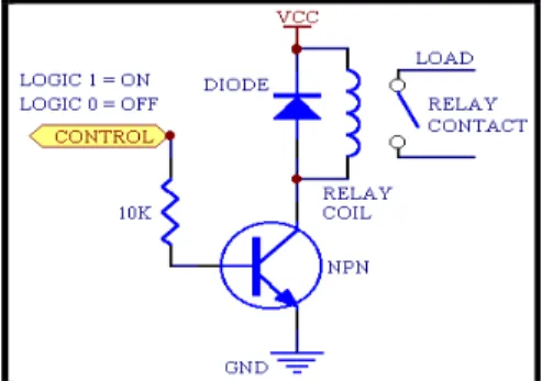
Figure 4-6: Relay Drive Circuit ... 17
Figure 4-7: Station C Code ... 18
Figure 4-8: Main Code Block ... 20
Figure 4-9: Sensor Class ... 21
Figure 4-10: Signal Bouncing ... 22
Figure 4-11: FIFO Class ... 23
Figure 4-12: Timer Class ... 23
Figure 4-13: Open and Close Counter Code ... 24
Figure 4-14: Station B Control Code ... 24
Figure 4-15: Station C Control Code ... 25
Figure 5-1: XY-Table System ... 27
Figure 5-2: Inside the Stepper ... 29
Figure 5-3: Bipolar Stepper ... 30
Figure 5-4: Unipolar Stepper ... 31
Figure 5-5: Stepper Driver ... 31
Figure 5-6: RS-232 Interrupt... 33
Figure 5-7: Dividing Received Command ... 34
Figure 5-8: MicroC Functions ... 34
Figure 5-9: Developed Functions ... 34
Figure 5-10: Branching According to Product Type... 35
Figure 5-11: XY-Table ... 36
Figure 5-12: Round Product View ... 38
Figure 5-13: Square Product View... 38
Figure 5-14: Square Image Scanning ... 39
Figure 5-15: Round Image Scanning ... 39
Figure 5-16: Pixel Information Storing ... 40
Figure 5-17: Analyzing the Image ... 42
Figure 5-18: Diameter Calculation ... 44
Figure 5-19: Edge Definition ... 45
x
Figure 6-2: FIFO Organization ... 47
Figure 6-3: XY-Table System ... 47
Figure 6-4: Complete System Flow Chart ... 48
xi
LIST OF ABBREVIATIONS
Software: SW
Conveyor System: CS
XY-table System: XY-TS
Computer Aided Drawing: CAD
Personal Computer: PC
Open Computer Vision Library: OpenCV Programmable Interrupt Controller: PIC Programmable Logic Controller: PLC Universal Serial Bus: USB
1
1.
INTRODUCTION
Subject of this master’s thesis is a particular industrial automation problem, which is called “sorting”. Sorting is faced frequently in industrial applications. Our set-up consists of two main mechanical parts. First one is a conveyor belt and the second one is an XY-table.
Our goal in this thesis was to create a test-bed for several technologies. We have shown that it is possible to design and implement everything from scratch in a university environment and with little financial investment. This test-bed and thesis write-up will allow students to learn the technologies involved, modify them, and see them in action in a bigger system. This system was a wonderful exercise for us in system integration, and it will be so for future students. To wrap it up, this system allowed us to gain experience in many aspects of industrial automation, and it will be so for students who will use this set-up. Each component of this system can be useful in a different system or by itself.
In our set-up, the conveyor belt performs the first sorting operation. There are three types of products. First one is tall and square. Second one is short and square. Third one is short and square. The sorting mechanism on the conveyor belt sorts out short products using a particular combination of infrared sensors and pushes them to the XY-table with a reject arm. On the other hand, the XY-table sorts the two types of short products (i.e., square and round). By using a vision system, we can tell square ones from round ones. After the vision system makes a decision, sorting is performed by driving steppers. As a result, squares are pushed into a different bin than the round ones, which are placed at different spots and next to the XY-table.
According to our performs, there are three different products travelling on the conveyor belt which the first sorting operation (Kazma et al. 2008). Products are moving on the conveyor belt non-stop, and they are sorted according to their length. On the conveyor belt, there are three main stations. First station is for detecting product type. There are two infrared distance sensors, two of which are placed vertically placed in station 1 called (Station A). If lower side sensor detects an object without the upper sensor
2
detecting anything, software adds a 0 to the FIFO. If both detect, then software adds a 1 to the FIFO.
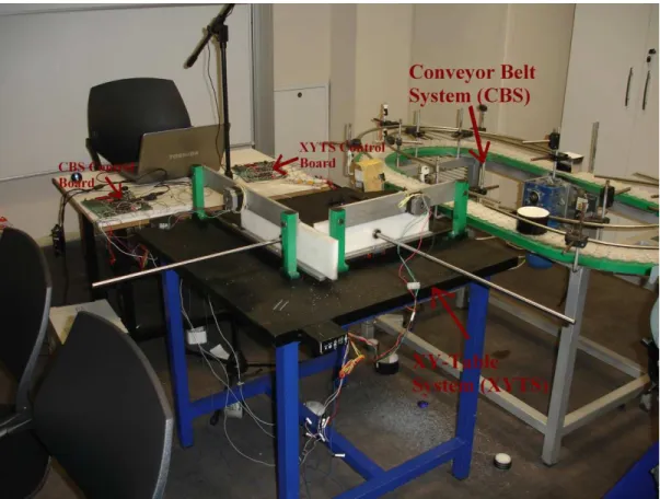
In order to design this master’s thesis’s assembly, AutoCAD drawing program was used. First of all, we designed the conveyor belt and XY-table on paper. After that, they were drawn by AutoCAD. The machine shop we worked with produced these two assemblies with the guidance of these technical drawings. The whole set-up is shown in Figure 1-1.
Figure 1-1: Complete System
Also, we have used a vision system on the XY-table to properly sort products according to their shapes. We had certain requirements for the XY-table. So as to prevent cabling problems, motors that move XY-table’s sorter arm had to be fixed. After doing some research on the net, a project web page was found at Florida Institute of Technology. They designed and implemented several XY-tables. We have been inspired by one of those designs while designing our XY-table system.
3
As we said before, in our system there are mainly two mechanical structures for sorting products. First one sorts products according to their height and second one sorts products according to their shapes. In order to analyze the shape of a product, we have used machine vision techniques (Uğurdağ & Sena 2005). In order to analyze products on the XY-table, we have to capture frames of pictures and send them to a PC to analyze shape type of the product on the XY-table. So we have placed a web camera over the XY-table.
In industrial applications, machine vision is the most commonly used method for sorting operations. For example, shipping firms are using machine vision to sort out products to see where they must be delivered. Also machine vision is used for in-vivo fish sorting applications (Zion, Shklyar & Karplus 2000).
In order to move to XY-table’s sorter arm, we have used stepper motors. Before that, we used special servo motors and its driver with a motion controller in the backdrop. However, during this work the motion controller got damaged. Therefore, we had to change motors and controllers. We have decided on stepper motors because it is easy to find stepper drivers and stepper motors. Also, we do not need to have highly sensitive motors, so stepper motors are enough for our XY-table.
Also, we have used OpenCV, which is developed by Intel Corporation, to analyze pictures of the sorted products. In order to write OpenCV software, we have used C#.Net programming language platform.
We have used a PIC (http://ww1.microchip.com 2009) microcontroller to control the conveyor belt and XY-table instead of PLC. Advantage of this is that the cost of PIC is less than PLC. Also, we developed a SW methodology for writing C code on PIC microcontrollers (Kazma, Đleri & Uğurdağ 2009).
4
2.
LITERATURE SURVEY
This thesis is a demo of an industrial application. As explained, the set-up contains two main structures, namely, a conveyor belt system and an XY-table system (which includes a vision system). Conveyor belt system and XY-table system are used for sorting.
There are a lot of methods in order to design a conveyor belt. Designing of conveyor belt depends on type of products. Low cost and efficient moving of product and safety are important factors.
Some methods were developed in order to optimize computer memory, cost of run time for microcontroller that is controlling conveyor belt, safety and efficient moving of products. In order to optimize these issues some methodologies were developed. One of them is resizing of conveyor’s belt according to size of products. This work was done in order to decrease size of free spaces in order to gain inactive spaces. Other one is that products are grouped when they are carried by conveyor belt. For example, letter transportation on conveyor belt. Letters are grouped in group of 100 parts. Also controlling number of grouped products is another method (Geinzer & Meszaros 1990). Glass bottles, metal cans, and plastic bottles are collected in a bags and containers in order to be recycled. These products also loaded on a to conveyor belt to be sorted. In our industrial application, there are three types of products on the conveyor belt to be sorted. As it is understood, all conveyor belt system is used neither transportation nor sorting mechanism (KITANI et al. 1999).
There are a lot of studies in the academic world for sorting systems. Some studies have been done which are two-stage sorting algorithms. In the following paper (Paclik, Raimund & Duin 2006) four groups of algorithms were developed. These algorithms are:
State-of-the-art algorithms:
5
o GLDB-FLD: spectra-specific feature extractor (a top-down Generalizer Local Discriminant Bases algorithm) followed by the FLD
o PCA-QDC: Principal Component Analysis (PCA) followed by quadratic discriminant assuming normal densities (QDC)
o PCA-3NN : PCA followed by the 3-nearest neighbour rule
o DBC-NN : nearest mean classifier using Spectral Angle Mapper (SAM) distance and mean class spectra as prototypes
• Dissimilarity-based approaches
o SAM-NN: object prototypes, SAM, 1-NN o SAM-FLD: object prototypes, SAM, FLD
o DerDist-NN: object prototypes, derivative dissimilarity,1-NN o DerDist-FLD: object prototypes, derivative dissimilarity,
• Decomposition-based descriptors
o MOGC: Gaussian mixture model built on original spectra
o PCA-MOGC: PCA dimensionality reduction, followed by MOGC o mode-SIMCA: for each mode a separate PCA projection and model is
built. The classification is performed based on the combination of in- model Mahalanobis and out-of-model Euclidean distance
o LDA-MOGC: Linear Discriminant Analysis (LDA) on data modes; MOGC in the resulting low-D subspace.
• Decomposition-based discriminants
o DMMD: both the sub-problem discriminants and the combiner are FLDs o GLDB-DMMD: for each sub-problem a specific feature representation
is first derived by the GLDB extractor. The FLD is used both as the first-stage classifier and as the combiner.
.
Another sorting method was developed in China in order to sort apples. This study has been done because of huge agricultural area of China, because China is producing 17 million tons apple in a year. Quality of production of apples is not good owing to not automated sorting phases. Sorting was done by workers. Therefore, weakness of human beings, workers may miss defected apples, because hand inspection can cause eye fatigue. Therefore, hand inspection is not efficient for 17 million tons apples.
6
In order to solve this problem, engineers needed to develop a new sorting method. To sort apples, machine vision techniques were used. As it is predicted, if an apple must be sorted according to surface defects, then all surface of an apple must be checked. So as to control the whole surface of an apple at least 4 cameras are needed. However this method was increasing cost of vision system, because 4 cameras mean 4 controllers and calibration of 4 cameras.
Instead of four camera engineers developed a vision system. According to this system, 2 mirrors and 2 cameras are used as it is shown Figure 2-1 (Li, Wang & Gu 2002).
Figure 2-1: Vision System of Apple Sorting
Also, another study on sorting systems is about sorting items on a moving conveyor belt. In this work a vision technique is used. According to this work, two main phases were used. First step was sensing object that was moving on conveyor belt and second one was gripping object in other word product. Sensing operation was important in order to detecting and classifying the items. Gripping step was used in order to separate out object.
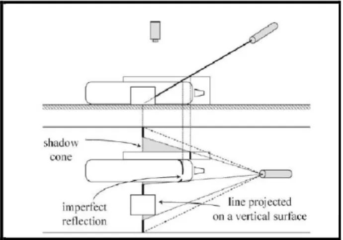
In order to sense an object, a CCD camera and laser beam were used as shown Figure 2-2. Also fuzzy techniques were used in order to identify the geometrical description and center of an item to find its optimal gripping point (Mattone, Campagiorni & Galati 2000).
7
• If, at the current point, the height is small, then the point does not belong to any segment (i.e., it belongs to the reference line and is called an external point).
• If, at the current point, the height is significant and the height step w.r.t. the last scanned (adjacent) point is small, then the point belongs to last detected segment (i.e., it is an internal point).
• If, at the current point, the height is significant and the height step w.r.t. the last scanned (adjacent) point is also significant, then the current point belongs to a new segment (i.e., it is a boundary point).
• If, at the current point, the height is undefined (we are in a so-called hole), then the current point is external (in order to avoid that a weak reflection of the laser light is badly interpreted as a boundary, missing information at very small holes is extrapolated from the adjacent points during the acquisition of the height profile).
8
3.
OVERALL SYSTEM ARCHITECTURE
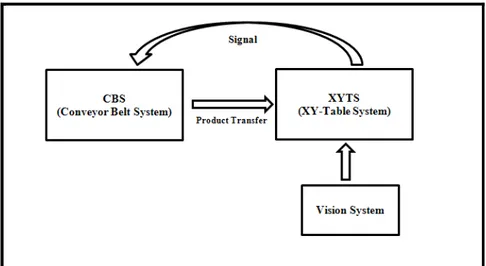
Basically, system architecture of this master’s thesis combines two main mechanical frames. Those are conveyor belt and XY-table. Both work simultaneously. Products that are sorted by conveyor belt are pushed on to XY-table to be sorted. Products are sorted according to height by conveyor belt. Small ones pushed onto XY-table. Also main structure is shown Figure 3-1. In order to see extended diagram look at Figure 3-3. Products that are pushed onto XY-table are sorted according to their shape. To understand the shape of product, vision techniques are used. A web camera is placed over the XY-table. This camera is capturing frames and sends to personal computer. In PC there is software that is written in C# .NET platform with openCV.
Figure 3-1: Overall System Diagram
As explained, the system combines two main structures. Those are conveyor belt and XY-table. Conveyor belt includes 380V AC motor to drive the conveyor belt, again 12V DC motor of windshield wiper to control reject arm. Two switches are used to open and close reject arm that pushes product to XY-table. Also, to sort the product, four infrared distance sensors are used. Two of the four are used to understand the height of products, one of the sensors is used to open reject arm and last one is used to close reject arm. Vertically placed two infrared sensors are used to define whether this product must be rejected or not.
9
Also on the XY-table, there are two stepper motors. They are used to move XY-table sorting arm through the vision based sorting mechanism. Steppers are moving two rods that are connected to each other. By this way, product can be easily pushed out from XY-table according to their shape. Products are pushed out into two separate bins. This means that round products are pushed out of left side of table, square products are pushed out of right side of table.
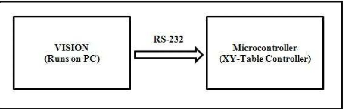
Figure 3-2: Vision System and Microcontroller Integration
To figure out shape of products, with a web camera, some machine vision techniques are use. According to this methodology, taken frames are sent to personal computer to be analyzed. After this analyzing step, shape of product and location information is sent to microcontroller. After that, according to this information microcontroller that controls table’s sort arm makes a decision. If product is square then arm of XY-table pushes products to left side of XY-XY-table. If square then product is right side of XY-table. Interaction between vision system and microcontroller is shown in Figure 3-2.
10
4.
CONVEYOR SYSTEM
Conveyor belt is a mechanical system that is used to move products from one location to another. Conveyor belt is a continuous loop that is mostly used by almost all factories that make serial production.
As it is known, conveyor belt system is used for efficient transportation of products from one location to another. Therefore, transportation of product becomes faster, easier and safer. Therefore, it is important to decrease cost of production.
Aim of conveyor belt that is used in the study is to transfer material from one location to another and also it is used to sort products according to height and shape products. There are four infrared distance sensors. Two of them are located vertically. Lower sensor detects products means that lower sensor’s signal goes up. After that, when lower sensor’s signal goes down, if upper sensor does not detect any object in other words, signal of upper sensor does not change, product passes just only in front of lower sensor. That means the height of product does not reach the upper sensor. So this product is a short one.
Other scenario is as follows after detection of lower sensor, if upper sensor detects product before lower sensor’s waveform goes down, it means that, vertically stacked two sensors, detect, in other words, wave form of two sensors go up at a common time. So we can say that the length of product is enough to reach upper sensor. So this product is tall.
11
4.1
CONVEYOR BELT ASSEMBLY
Figure 4-1: Conveyor Belt System
In master’s thesis, one directional linear speed conveyor belt is used. Used conveyor belt is produced by a company that is producing industrial machines. Technical drawing of conveyor belt is designed and drawn and given to a machine shop to produce it as shown in Figure 4-1.
If we consider specification of conveyor belt:
• Rotation speed: 720 m/hr
• Height: 80 cm
• With: 50 cm
• Radius: 50cm
• Made of: Steel and Teflon 4.1.1 Reject Mechanism
As it is explained before, conveyor belt that is used in the work is not only transferring products from one location to another, but it also includes a sorting mechanism. Therefore, there are four infrared distance sensors in order to sort product according to their length. According to decision of sensors, some of product must be rejected form conveyor belt to XY-table.
12
According to sensors’ value, reject arm is opened to sort product. Vertically stacked two infrared distance sensors identify height of products. After that, if one infrared distance sensor placed on conveyor belt after vertically placed two infrared sensors, generates pulse. Means that, when any product pass in front of third infrared sensor, if passed product is shorter one, then reject arm opens. When third infrared sensor generates pulse that means product closes to reject arm of conveyor belt. If product that passes in front of third infrared sensor is shorter one, reject arm is opened. To open reject arm, PIC microcontroller 16F877A applies pulse to relay circuit to drive 12V relays. Also relay drives 12V windshield wiper’s motor until arm opens sufficiently, microcontroller stops applying voltage to relay circuit. Microcontroller drives relay circuit till reject arm touches switch. After touching switch, microcontroller decides that reject arm is opened sufficiently.
To close reject arm, microcontroller waits for a pulse from fourth infrared distance sensor. Fourth infrared sensor generates pulse when product passes in front of it. Means of generating pulse of fourth infrared distance sensor, product that must be rejected is within reject range. Therefore reject arm can be closed. To close reject arm, microcontroller applies pulse to relay circuit till reject arm touches the switch. After touching the switch, microcontroller decides that arm is closed respectively and product rejected to a new sorting station (XY-table).
4.1.2 Infrared Distance Sensors
In order to identify product type and in order to open and close reject arm to sort products that are pushed out from conveyor belt, Sharp infrared distance sensors are used. Four infrared sensors are used in the whole system. Vertically placed infrared distance sensors are used in order to identify the height of product. According to sensors’ output, microcontroller decides which one is shorter and which one is taller. Microcontroller listening to lower one of the vertically stacked sensors that is placed in low state. When lower sensor generates a pulse, microcontroller starts to listen to upper infrared distance sensor till lower infrared sensor pulse waveform goes dawn. If upper sensor does not generate pulse, while lower infrared distance sensor is generating pulse
13
that means the product that just went by this is a short one. Length of product does not reach upper side infrared distance sensor.
On the other hand, if upper sensor generates pulse, while lower sensor is generating pulse. In the other words, if product that passes in front of vertically placed sensors is a tall one, two sensor generate pulse at the same time. Then the microcontroller decides type of product that passes in front of sensors is a tall one. Therefore, although third sensor that is placed to open reject arm when product closes to reject station produces pulse, microcontroller does not care that pulse. Since, product is a tall one, it is not rejected.
4.2
CONVEYOR BELT CONTROL SOFTWARE
There are two different softwares developed to control the conveyor belt. The software that is developed first is developed without using switches that are used to stop reject arm when it is closing and opening. When reject arm touchs switch, microcontroller stops to drive relay. Therefore, opening or closing routine is stopped by using these switches.
Second one is developed without switches. In order to stop closing or opening reject arm, a counter defined. When product pass in front of infrared distance sensors (http://cnmat.berkeley.edu 2008) counter starts to count and arm starts to open, when counter reached defined value, counter is set to zero and to open or close reject arm, driving relay circuit is ended.
4.2.1 Using Switches
In order to control conveyor belt, a methodology is developed. According to this methodology, to open and close reject arm two switches are used.
After deciding for a product that whether it is rejected or not, product passing in front of third infrared distance sensor Station B, if product must be rejected, then microcontroller applies voltage to relay drive circuit till reject arm touches the switch. When reject arm touches to the switch, a logic voltage goes to microcontroller, so microcontroller stops applying voltage to relay drive circuit.
14
After that, if the last infrared sensor that is placed to understand product is in front of reject arm produces a logic voltage, microcontroller starts to apply logic voltage to other relay drive circuit to turn off reject arm and pushes out the product till reject arm touches the other switch. Again, when reject arm touches the other switch that is used to understand whether reject arm is closed or not, a logic voltage goes to microcontroller and microcontroller stops to apply voltage to relay drive circuit to close reject arm. 4.2.1.1 Explanation of Developed Software
To develop conveyor belt control software “microC for PIC” compiler that is produced by Mikroelektronika Corporations is used.
1.while(1) { .
. . n.}
Figure 4-2: Main Code Block
All code block is written between this infinite while loop that is shown in Figure 4-2. Therefore all algorithms infinitely repeat.
1. while( Adc_Read(0) > 450 ) 2. { 3. PORTC.F0=1; 4. flagForNeg=1; 5. delay_ms(50); 6. if(Adc_Read(1)/450> ) 7. { 8. valFifo=1; 9. PORTC.F1=1; 10. } 11.}
Figure 4-3: Station A Code
As explained before, there are two vertically placed infrared distance sensors. Upper side sensor is connected to microcontroller’s analogue port, which called PORTA. When a product passes in front of infrared sensor that is connected analog port’s first pin, an analog voltage goes to microcontroller. In the Figure 4-3, in line 1, written a while loop that is “while( Adc_Read(0) > 450 )”. By using a special microC function “Adc_Read(pin_number)” analog port of microcontroller is listened. When analog voltage value that is produced by infrared sensor, bigger than “450”, SW code block
15
branches into while() loop and SW runs till condition that is value of sensor bigger than “450” becomes false. During code block in “while( Adc_Read(0) > 450 )” loop, if “if” block condition becomes true at line 6, so vertically placed upper infrared sensor (that is vertically upper one) detects a product code block goes into “if” block and an integer variable “valFifo” assigns “1“. In Figure 4-3 between 6-9th lines SW does this operation.
When product is passing in front of vertically placed infrared sensors, condition of “if(Adc_Read(1)/450> )” is not true while SW runs in “while()” loop, that means product is a short one. So value of an integer variable “valFifo” default becomes 0. And also in line 4, there is “delay_ms(50)” to solve the bounce problem.
1. if(flagForNeg) 2. { 3. FiFo[i]=valFifo; 4. i=i+1; 5. flagForNeg=0; 6. valFifo=0; 7. PORTC.F0=0; 8. PORTC.F1=0; 9. }
Figure 4-4: Product Information Pushed into FIFO
In Figure 4-3, while condition correction becomes true in line 1, at line 4 there is “flagForNeg=1;” code. After correction of integer variable “flagForNeg” becomes 1. Therefore, if vertically placed lower side infrared distance sensor detects an object code block waits till Figure 4-4 line 1 code becomes false. Therefore, “flagForNeg” becomes true. After passing product in front of sensor finished that “while“ condition becomes false and “flagForNeg” becomes 1. Therefore SW can understand product passed in front of sensors.
Therefore, in Figure 4-4 line 1 if condition verifying true and do all operation into the “if” block. As it is seen line 2, there is an integer array called “FIFO[0]” and “valFifo” constant that is assigned to array. As explained before value of “valFifo” constant, changed owing to length of product. When product is passing in front of vertically placed sensor, upper side sensor does not create pulse during lower side sensor producing pulse, which means passing product is shorter one. In this situation, value of “valFifo” becomes 0. On the other hand, during lower sensor producing pulse
16
simultaneously, if upper sensor produces pulse value of “valFifo” becomes 1. Value of “valFifo” assigned to array (FIFO[0]).
During operation, many products can pass in front of station 1 called Station A that is classifying products according to length of them before first classified product it is arrived to reject station. Therefore, passed products must be stored in orderly. That means, when first product arrived to reject station it must be defined as that will be rejected or not.
So as to store information about products that are passed in front of sensors, FIFO (First In First Out) algorithm is used. According to this algorithm, passed product in front of vertically placed sensors, information about length of product is pushed into a FIFO named “FiFO[index]”, index is 0 and 1. Also when product arrives at reject station, SW looks at the FIFO’s top member and decides whether it will be rejected or not. If value of top index of FIFO array is 0 then reject arm is opened and product is rejected, if value is 1 then product continues its own way. After product passes through third station called Station C, FIFO array will be updated by swapping member of FIFO array.
1. if(Adc_Read(2) > 450 && flag == 1) 2. { 3. flag=0; 4. PORTC.F2=1; 5. if(FiFo[0]==0) 6. { 7. flagforrej=1; 8. PORTC.F5=1; 9. while(PORTC.F1==0); 10. PORTC.F5=0; 11. for(ii=1;ii<30;ii++) 12. { 13. FiFo[ii-1]=FiFo[ii]; 14. } 15. FiFo[i]=-1; 16. i=i-1; 17. } 18. else if(FiFo[0]==1) 19. { 20. for(ii=1;ii<30;ii++) 21. { 22. FiFo[ii-1]=FiFo[ii]; 23. } 24. FiFo[i]=-1; 25. i=i-1; 26. } 27. }
17
At Station B, which is also controlled by an infrared distance sensor connected to microcontroller’s 3rd analog pin, according to product information, reject arm is opened to push out product or let it pass. In Figure 4-5, line 1, if infrared distance sensor detects an object that means value of microcontroller’s analog port’s 3rd pin is higher than 450. When this condition is true then code block branches into “if” block. In this “if” block also there is another “if” block to control whether product that is in Station B is shorter one or not. To control it, SW looks at FIFO’s first member. If first value of FIFO is 0, that means if “if” block at line 5 is true, then to open reject arm SW runs 8th line PORTC.F5=1; to open reject arm. Therefore, SW applies logic voltage to digital port of microcontroller’s 5th pin and microcontroller drives relay. In order to drive it current must be higher so by helping relay drive circuit, current have done higher till reject arm touches the switch. In Figure 4-5 in line 9, “while(PORTC.F1==0);” code block means that SW waits till reject arm touching to the switch. When reject arm touches switch then PORTC.F1 equals 1 and breaks while loop and do next line. In next line, software runs code to stop to apply voltage relay drive circuit so as to end reject arm closing operation PORTC.F5=1; stopping to apply voltage to relay drive circuit. After that, to control next product, FIFO array must be updated. To update FIFO array all member of array is swapped that is shown in Figure 4-5 between line 11 and line 16.
Figure 4-6: Relay Drive Circuit
If correction of “if” at line 5 does not true, then code goes directly to line 17. Check correction of 17th line correction. If it is correct, code block goes into the “if” block and just swap FIFO array as shown in Figure 4-5 between line 17 and line 26.
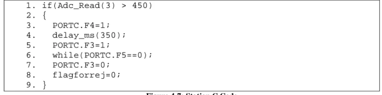
18 1. if(Adc_Read(3) > 450) 2. { 3. PORTC.F4=1; 4. delay_ms(350); 5. PORTC.F3=1; 6. while(PORTC.F5==0); 7. PORTC.F3=0; 8. flagforrej=0; 9. }
Figure 4-7: Station C Code
After opening reject arm, to reject product, reject arm must be closed. In order to reject product, SW must be sure product is within reject range or not. To control this station, there is also an infrared distance sensor. In Station C station, product is in within range and ready to be rejected. To control whether product within reject range at Figure 4-7 line 1 “if(Adc_Read(3) > 450)” condition written. If this condition becomes true that means product is in front of reject arm, reject arm can be closed and shorter product is rejected to XY-table for new sorting operation.
When this condition becomes true, then code bloc branches in to the “if” block and do operations. According to these operations SW do “PORTC.F3=1;” and start to drive relay circuit to close reject arm till reject arm touches to the switch and pushes out product to XY-table. When reject arm touches the switch, logic voltage goes to microcontroller’s digital PORTC.F5 and stop to driving relay by “PORTC.F3=0;” command.
4.2.2 Without Switches
Without switches, microcontroller applies logic voltage to a circuit that makes voltage higher to drive relays. To open or close reject arm, microcontroller must apply voltage to relay drive circuit in a constant time in order to see relay drive circuit look at Figure 4-6. That means, microcontroller is applying voltage to circuit, and starting to sleep during 350 milliseconds. During sleeping, if a product passes from Station A, SW may miss product and cannot have any information about it.
19
1. void main() 2. {
3. int i=0, flagForNeg=0, valFifo=0, ii, flag=1, flagforrej=0; 4. int FiFo[30]; 5. TRISB = 255; 6. PORTB = 0; 7. TRISC = 0; 8. PORTC = 0; 9. Adcon1 = 0; 10. TRISA = 255; 11. PORTA = 0;
12. for(ii=0; ii<30; ii++) 13. { 14. FiFo[ii] = -1; 15. } 16. while(1) 17. { 18. while( Adc_Read(0) > 450 ) 19. { 20. PORTC.F0=1; 21. flagForNeg=1; 22. delay_ms(50); 23. if(Adc_Read(1)/30 > 15) 24. { 25. valFifo=1; 26. PORTC.F1=1; 27. } 28. } 29. if(flagForNeg) 30. { 31. FiFo[i]=valFifo; 32. i=i+1; 33. flagForNeg=0; 34. valFifo=0; 35. PORTC.F0=0; 36. PORTC.F1=0; 37. }
38. if(Adc_Read(2) > 450 && flag == 1) 39. { 40. flag=0; 41. PORTC.F2=1; 42. if(FiFo[0]==0) 43. { 44. flagforrej=1; 45. PORTC.F5=1; 46. delay_ms(200); 47. PORTC.F5=0; 48. for(ii=1;ii<30;ii++) 49. { 50. FiFo[ii-1]=FiFo[ii 51. } 52. FiFo[i]=-1; 53. i=i-1; 54. } 55. else if(FiFo[0]==1) 56. { 57. for(ii=1;ii<30;ii++)
20 58. { 59. FiFo[ii-1]=FiFo[ii]; 60. } 61. FiFo[i]=-1; 62. i=i-1; 63. } 64. } 65. else if (Adc_Read(2) < 450) 66. { 67. PORTC.F2=0; 68. flag=1; 69. } 70. if(Adc_Read(3) > 450) 71. { 72. PORTC.F4=1; 73. delay_ms(350); 74. PORTC.F3=1; 75. delay_ms(200); 76. PORTC.F3=0; 77. flagforrej=0; 78. } 79. else if(Adc_Read(3) < 450) 80. { 81. PORTC.F4=0; 82. } 83. } 84. }
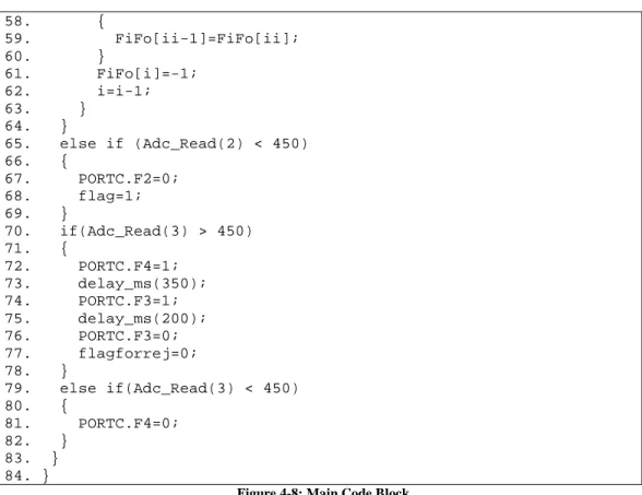
Figure 4-8: Main Code Block
In this algorithm, there are no switches to control whether reject arm is opened enough or not. It is done just by using “delay_ms(ms);” command. Therefore when applying this command, SW goes sleep and miss passing products.
According to all code when product passing in front of Station A station, information about it pushes into FIFO array. And Station B, according to FIFO array value, rejects arm opens or does nothing. In order to open reject arm for constant time, SW applies logic voltage to relay drive circuit. In Figure 4-8 between line 38 and line 47 do this operation. In 47th line, SW goes to sleep during 200 milliseconds.
Also to close reject arm in Figure 4-8 between line 69 and line 77 SW goes to sleep during 200 milliseconds. There is a code line at line 74 “delay_ms(200);” to sleep SW during 200 milliseconds. Therefore, SW is missing products that are passing in front of Station A. Therefore, to prevent from “delay_ms(ms);” commands switches are used.
21
4.2.2.1 With Counters
To control conveyor belt, a new methodology is developed. According to proposed methodology, basically consists of two main parts. The first working in parallel with each other station procedures, other one is other procedures used to create class libraries. As it is seen the conveyor band sensors are placed in three different positions. These sensors’ locations can be considered as a different station. The main procedure is the responsibility of the system, stations of its own sub-procedure is to run in parallel. Library Functions
Figure 4-9: Sensor Class
For this automation solution methodology, there are three different class libraries. These are sensors, FIFO and the time-meter (timer). Sensor class and this class library’s functions are shown in Figure 4-9 used sensors are produced wavy / should bounce signals. This signal is operated and decided, whether a new product is passed in front of infrared distance sensor or not. To apply this decision operation, SW analyzes threshold value that is pre-determined, and decides whether it is new product or not. If the signal is higher than the threshold value, it must be shielded during constant time. If SW does not do this operation, although passing just one product in front of infrared sensors, SW can determine passing more than one product.
So as to, debounce methodology is used to solve this problem. To use this debounce technique in PIC microcontroller, actual value of sensor and previous value of sensor must be held to define posedge. Therefore these two values are added to library class. Members of sensors library “threshold” holds threshold values, “portNo” holds which port that sensors are connected, “currentValue” holds current values of sensor,
22
“previousValue” holds sensor’s previous value, “debounceTimer” shield time counter’s constant time value and “debounceInterval” holds value of shield interval.
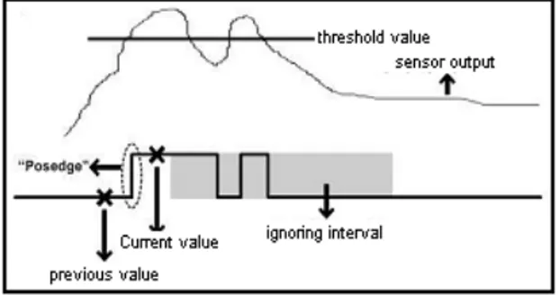
Figure 4-10: Signal Bouncing
Procedure of “initSensor” takes number of sensor as a parameter. According to this parameter this procedure initializes initial value of parameters that are in the library class. Also another procedure called “vewPart” is used after taking number of sensor, initialize current value to previous value. After this initializing operation, signal that produces next step initializes current value of sensor. After taking value of previous and current values of sensor, SW decides new part of product is passed in front of sensor. Value called posedge, with inverted value of sensor’s signal’s previous value, current value of sensor is logical ended, result gives whether new product passes in front of sensor or not. If result is 1 that means new part passes. At this situation, SW understand that new product is passing in front of sensor, time counter and shield are activated. Therefore, during determining a new part passing in front of sensor operation, shield interval is ignored, so microcontroller decision is not affected because of wavy/jumping. When time counter reached shield interval that is before defined, it is again assigned to its initial value. Therefore, decision statements are activated. Value of posedge, wavy/jumping signal that is produced by infrared distance sensor and shield interval is shown in Figure 4-10. By the way using this methodology that is used in digital hardware design, error rate is minimized.
Member of FIFO library classes are shown in Figure 4-11. Those are “mem[FIFO_SIZE]” that holds FIFO’s data. FIFO is designed as circular buffer. Benefit of this is that during data writing and reading from FIFO, swapping is not necessary. “rdPtr” holds array indices that points data that reads from FIFO array. In
23
this point (“mem[rdPtr]”), member of top of the FIFO is the oldest value. “wrPtr” is holds writing point. When new product type information is written in FIFO, SW looks “wrPtr” value and writes information this point of FIFO. This “wrPtr” is last point of queue and empty space. There are also two flags that are called full and empty. Full is true if FIFO is not have space to hold new product information and empty is true if FIFO is still have free location to hold product length information. “initFifo()” routine that is member of FIFO class library initializes FIFO library class’s members. If FIFO is not empty, value of the position that is shown by “rdPtr” is read deleted from FIFO (actually just value of “rdPtr” is increased). The last routine of FIFO library class is “pushFifo()”. “pushFifo()” writes information about product to FIFO’s last location by increasing “wrPtr”.
Figure 4-11: FIFO Class
Figure 4-12: Timer Class
“Time-counter” is the last class library. Member and procedure of this “Time-counter” class library are shown in Figure 4-12. This class is basically integer. By using “initTimer()” procedure, “Time-counter” is set up as a chronometer. If “updateAndREturnTimer()” function that is member of “Time-counter” class library is called in main routine, “Time-counter” count down like a chronometer till time-counter reach 0. This function is a type of sleep function that can be interrupted. When “Time-counter” reached 0, “Time-counter” finished required time interval.
24
4.2.2.2 Explanation of the Code
According to this methodology, an integer counter is defined. After product passing through Station A, it is defined whether it is rejected in or not. After product arriving Station B station if it will be rejected, an integer variable start to count till it reaches to constant value.
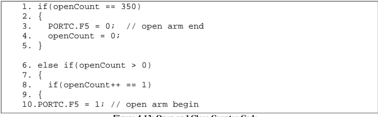
1. if(openCount == 350) 2. {
3. PORTC.F5 = 0; // open arm end 4. openCount = 0; 5. } 6. else if(openCount > 0) 7. { 8. if(openCount++ == 1) 9. {
10.PORTC.F5 = 1; // open arm begin
Figure 4-13: Open and Close Counter Code
In Figure 4-13 at line 1, there is an “if” condition at first line. That means when an integer value “openCount” reaches to 350 by Appling “PORTC.F5 = 0;” command, SW stopping to apply logic voltage to relay circuit. Initialize “openCount” to 0 for new opening operation.
As it is seen that in Figure 4-13 at line 10 there is a “PORTC.F5 = 1;” code. It means that start to apply logic voltage to relay drive circuit. When infrared distance sensor that is controlling Station B detects an object apply voltage to relay drive circuit till “openCount” reaches 350.
1. if(withinRangeSensorNegedge) 2. {
3. if((withinRangePartDefective = popFifo(0)) != NO_PART) 4. { 5. fifoCount--; 6. pushFiFo(1, withinRangePartDefective); 7. if(withinRangePartDefective == DEFECTIVE) 8. { 9. openCount = 1; 10. } 11. } 12. }
25
In Station B, when infrared distance sensor detect an object, SW looks FIFO array to understand whether product that passes in front of Station B station is rejected or not at line 5. If it will be rejected at line 6, “openCount = 1;” code runs and “openCount” start to count till 350.
1.if(arrivedSensorPosedge) 2.{ 3. arrivedPartDefective = popFifo(1); 4. if(arrivedPartDefective == DEFECTIVE) 5. { 6. closeCount = 1; 7. } 8.}
Figure 4-15: Station C Control Code
If Station C’s infrared distance sensor detect product and reject arm is opened, then run this code “closeCount=1;” to start to count “closeCount” counter. It is reached to 350 microcontroller stop to apply logic voltage to relay drive circuit. That is shown in Figure 4-15.
26
5.
XY-TABLE SYSTEM
XY-table is a type of basic two axis robot. XY-table, which is generally called plotter, has many different types. Basic ones have just two axes. Also, they have many application areas for example; chemistry, product assembly, etc. There is also plotter, which has many movement axes. They are flame cutting machines, CNC machines, etc. As a characteristic, XY-tables move in two axes in space. In order to make it move two or more stepper motor, servo motor or DC motors are used, which are driven by a special electronic circuit, which are called drivers. Also drivers are controlled by special microcontroller or microprocessor based control cards (PLC, PIC, etc.) to apply pulses to the drivers.
In this master’s thesis, XY-table is another sorting mechanism. Machine vision techniques are used to identify products that are pushed out from conveyor belt. A web camera is placed over the XY-table to detect object. After detection object that is pushed out from conveyor belt, vision SW analyzes shape type of product.
According to product shape, XY-table has been pushed product out from table. If shape of product is square, then it is pushed out from right side of the table. If it is round, then it is pushed out from left side of table
To determine shape of product, two different algorithms are defined and implemented. According to first algorithm, frame that is taken from web camera is analyzed. Frame is scanning pixel by pixel by stepping 10 pixels. When pixel crashed to white one coordinate value of pixel stored. In one frame actually 10-12 pixel Y axis coordinate information is stored. Then first coordinate value is subtracted from second coordinate value and second coordinate value is subtracted third one and goes on. If difference of subtraction is same then shape is square. Because one side of square is line so as to with subtraction of any two points must be same. However, round does not apply this rule. So if there is no linearity then we can say it is not square, it must be round.
27
This first algorithm just defines whether product is square or not. However, if any different shape type is pushed out from conveyor belt to XY-table, vision SW cannot detect object clearly. That is why; XY-table can push out product from wrong places. To eliminate this problem, a new algorithm is developed and implemented. In order to take advantage from ratio of perimeter root mean square to area. According to this advantage, ration of perimeter root mean square to area is 4 for square and 3.6 for round. By this way, it is easy to understand whether or not it is undefined object.
Also there are two different types of algorithm for XY-table. Algorithms are developed according to methodology. First methodology is sorting all products on the XY-table. This methodology is given up, because there is not enough space on the table to store products. By the way, products are pushed out from different places according to shape of them instead of storing on the table.
5.1
XY-TABLE ASSEMBLIES
Figure 5-1: XY-Table System
XY-tables are generally designed for some processing on about products. Most known operations are shaping products, flame cutting, plotter etcetera. At least, XY-tables make two moves axially as shown Figure 5-1. For high quality XY-tables must be so sensitive. By the way, for certain and lossless move software that runs to control
XY-28
tables written clearly and include some control algorithms, of course if needs. Also to produces XY-table must be protected from backlashes for lossless moves.
Master’s thesis’s XY-table is produced in a factory. It is designed for master’s lecture. Result of internet research, design of XY-table found at FID University’s lecture’s term project. Design of XY-table is directly taken. After some modification, XY-table of master’s thesis is appeared.
• If we consider specification of XY-table;
• Rotation speed: 25 km/hr.
• Height: 80 cm
• Width: 75X75 mc
• Made What: wood 5.1.1 Stepper Motors
Stepper motors (http://en.wikipedia.org/ 2009) are brushless electric motor that we can divide a full rotation into a large of steps as it is shown Figure 5-2. For example when we divide a full rotation into 1000 steps, when we apply 1 clock cycle to steppe, motor rotator returns just 0.0365 degree. So we can control motor position precisely.
When electric is applied to DC motor, it just rotates. However steppers have multiple toothed electromagnets. When electric is applied to one of electromagnet, motor shaft makes one step. As repeated, after applying electric to one toothed, electromagnets are slightly offset the next electromagnets. After that, when we applied electric to next electromagnet it is turn on and first one is turn off. So gear rotates slightly to align with next electromagnet.
29
Figure 5-2: Inside the Stepper
To rotate stepper motors, electric cannot be applied directly to electromagnets. To drive steppers a special circuit is needed that are called stepper driver. As it is understood, stepper motors are not close loop control systems. It is an open loop control system. Any feedback information is not being taken from stepper. When steppers are overloaded, stepper cannot catch exact position. Because electromagnets may be change their location because of overload.
Step motor terminal voltage is applied to the classic DC motors are different from returning. Step motor square in the centre of a lot of gears is gear electromagnets. With an external control circuit such as this electromagnets and energy are electromagnets. To move the motor shaft power is provided primarily to electromagnets. The teeth of the wheel centre with electromagnets teeth enters into interaction with each other. Head of the teeth of the wheel is aligned to the first electromagnets is the next electromagnets energy. First electromagnets was closed, the second will return a little more when the centre wheel. These steps will continue the same for other electromagnets. Each step of this movement is small, means that the desired action step can be provided at an angle. Step motors are still powerful engine (power = angular velocity x torque). Increase engine speed, the torque will decrease. Torque curve, or using the drive current limit may be extended by increasing the driving voltage.
Step motors than other types of engine vibration are shown. This vibration causes some speed to lose value as the engine's torque can be converted become harmful. This issue will create vibrations in the engine speed range can be solved. Moreover, the number of
30
phase motors in excess of the number of phases to be less than the engine vibration performs the work.
Also there are two phase stepper motors, that are, unipolar and bipolar steppers. The logic is that per phase unipolar step motor includes two windings. Current direction is for one of these windings. Movement direction of the magnetic poles through this coil can be inverted without change. For each circuit of the circuit is very simple, commutation is done in a way. Usually, one end of the phase is common for each coil end, and there are three per phase. Common 2-phase step motor end usually comes from outside. That stepper is only 5-end. End coil with discern common use is the most healthy method resistance measurement. Resistance between the tip end of the coil, coil resistance between the end-coil end is always half.
Figure 5-3: Bipolar Stepper
When the steppers start to fall to less than one coil, it is called bipolar steppers as it is shown Figure 5-3. This is why we drive the more complex circuits and driver circuits are usually derivatives of H-bridge. There are two ends per phase and there is no common end. Using the same weight as a result of bandage is better than the unipolar motor.
Such as step motor was wrapped 8
However, partners do not come from outside edge. This kind of engine can be established in different ways.
5.1.2 Stepper Motor Drivers
It is so difficult to drive stepper motors by applying direct electric to steppers’ electromagnets. So, step motor driver ci
more quickly they can change the torque curve can be extended, where the winding inductance limit will occur. Inductance problem is quickly overcome and the windings at this time are the key driver voltage
driver shown in Figure 5
31
Figure 5-4: Unipolar Stepper
Such as step motor was wrapped 8-ended unipolar step motors Shown in Figure 5 However, partners do not come from outside edge. This kind of engine can be established in different ways.
Drivers
to drive stepper motors by applying direct electric to steppers’ electromagnets. So, step motor driver circuit is needed to drive them. If the stator poles more quickly they can change the torque curve can be extended, where the winding inductance limit will occur. Inductance problem is quickly overcome and the windings at this time are the key driver voltage must be increased. A basic diagram of stepper driver shown in Figure 5-5.
Figure 5-5: Stepper Driver
Shown in Figure 5-4. However, partners do not come from outside edge. This kind of engine can be
to drive stepper motors by applying direct electric to steppers’ rcuit is needed to drive them. If the stator poles more quickly they can change the torque curve can be extended, where the winding inductance limit will occur. Inductance problem is quickly overcome and the windings A basic diagram of stepper
32
5.1.3 Web Camera
As it is explained before, XY-table is another sorting machine. Products that are pushed from conveyor belt that is first sorter machine are sorted by XY-table according to shape of products. Therefore by using OpenCV software that is written on .NET platform by using C# programming language shape of products are defined. A web camera that is over XY-table is used to take frames. Frames are sent to PC by web camera.
5.2
XY-TABLE CONTROL SOFTWARE AND VISION SOFTWARE
XY-table makes movements according to vision software decision. XY-table and vision systems work properly.
According to this, product that is pushed out from conveyor belt to XY-table is defined by vision system. According to this definition, type of product that is round or square and location of product on XY-table is defined by vision system.
After all definition of about product, all information is sent to PIC microcontroller that controls XY-table to sort product via RS-232.
5.2.1 XY-Table Control Software
As explained before, computer sends information about product that is on XY-table. Information contains about product type that means it is round or square and product location on XY-table via RS-232.
The format is “BCoorXCoorYSE”. This information is sent to microcontroller to sort product by vision software via RS-232. Microcontroller side is receiving this data and analyses and decides which product type is on XY-table and where it is location. To receive this data an interrupt routine is written for PIC microcontroller.
33 1. void interrupt() 2. { 3. if( PIR1.RCIF ) 4. { 5. read[ind] = Usart_Read(); 6. ind++; 7. if(read[ind-1]=='E') 8. { 9. parcala_behcet=1; 10. read[ind]='\0'; 11. ind=0; 12. } 13. } 14. PIR1.RCIF=0; 15. } Figure 5-6: RS-232 Interrupt
According to baud rate synchronization between microcontroller and PC an interrupt must be written. Firstly a char array defined. It has 12 members because of data that is sent by personal computer that runs on vision software. After microcontroller starts to run software inside of it, software is interrupted when a new data comes to microcontroller’s PORTC’s 7th pin till special command “E” arrived to microcontroller in Figure 5-6shown all explanation.
When letter “E” is arrived to microcontroller “'\0'” is added to last member of char array. By the way when microcontroller started to analyze command that is sent by personal computer, it can easily divide pieces.
When “E” is arrived microcontroller it means all information about product information that is stored in char array so array must be ended. To end char array, software add “'\0'“ end of char array. Look at line 10 in Figure 5-6.
A bool value “received” becomes true after last letter “E” is arrived to microcontroller. By the way in main routine there is an “if” shown in Figure 5-6 line 1block to check whether all command is arrived to microcontroller or not. If “received” becomes true, then in main routine “if” becomes true and does all operation in “if” block in Figure 5-6.
34 1. if(received==1) 2. { 3. while('x'!=read[xloc+1]) 4. { 5. locx[dix]=read[xloc+1]; 6. xloc++; 7. dix++; 8. yloc=xloc+1; 9. if('x'==read[xloc+1]) 10. { 11. locx[dix]='\0'; 12. xloc=0; 13. dix=0; 14. break; 15. } 16. } 17. }
Figure 5-7: Dividing Received Command
According to these operations all char array divided into parts. These parts contain shape type, coordinate X and coordinate Y that are coordinate of product on XY-table. After that coordinate information about product converted to integer value by using special function of microC compiler. That is shown in Figure 5-8.
1. locationx_int=atoi(locx); 2. locationy_int=atoi(locy);
Figure 5-8: MicroC Functions
Also received command includes product type. After char array broken into pieces, according to product type special functions are called to sort product. In order to sort product 5 different function is written. These functions are shown in Figure 5-8.
1. void ToHome();
2. void SquareToLine(int, int); 3. void RoundToLine(int, int); 4. void SquareOut(int, int); 5. void RoundOut(int, int);
Figure 5-9: Developed Functions
In Figure 5-9 “ToHome();” function is written. Because of this after sorting operation is finished, reject arms are brought back to initial station. “SquareToLine(int, int);” is used for that square product is bringing on square product sort line also “RoundToLine(int, int);” product is bringing on round product sort line.
35
“SquareOut(int, int);” after bringing product square line, it is ready to push out in other words it is ready for sorting. Also “RoundOut(int, int);” is used to sort round product to out.
A char array is defined to store product information called “shape[];”. In Figure 5-10 at line 1 and 16 there are two “if” block to check product type. If product type is round then code block branches in first if block and do all operation because of “if(shape[0]=='C')”. According to this operation round product is sorted. On the other hand is product is square then code block is branching into 9th line if block and sort product from its special location.
As it is seen that there are “ToHome();” function at line 7 and 15. After sorting operation reject arm turns back to initial station because of “ToHome();” function. To turn back reject arm LIFO algorithm is used. To implement this algorithm an integer array is defined that is “pos[14];”.
As it is seen, there is “ToHome();” function at line 7 and 15. After sorting operation reject arm turns back to initial station because of “ToHome();” function. To turn back reject arm LIFO algorithm is used. To implement this algorithm an integer array is defined that is “pos[14];”. According to this algorithm, each movement is storing into
1.if(shape[0]=='C') 2.{ 3. INTCON.GIE=0; 4. shape[0]='A'; 5. RoundToLine(locationx_int,locationy_int); 6. Delay_ms(400); 7. ToHome(); 8.} 9.if(shape[0]=='S') 10.{ 11. INTCON.GIE=0; 12. shape[0]='A'; 13. SquareToLine(locationx_int,locationy_int); 14. Delay_ms(400); 15. ToHome(); 16.}