The design of a wideband and widebeam piston
transducer in a finite closed circular baffle
Z. Sahin
aand H. Koymen
ba
Aselsan A.S., Mehmet Akif Ersoy Mah. 16.Cad. no:16, Macunkoy, 06370 Ankara, Turkey
bBilkent Univ., Dept. of Electrical and Electronics Engineering, 06800 Ankara, Turkey
Abstract- The design of a high power piezoelectric underwater transducer operating at frequency range 40
kHz-80 kHz with acoustic power capability in excess of 250W is described. The transducer consists of two
back-to-back elements. Each element is formed by stacked PZT-4 ceramic rings, a matching and a steel back-to-backing layer, and placed in a finite rigid circular baffle. We investigate the dependence of bandwidth and beamwidth to the combination of piston and baffle radii, a and b, respectively. With ka of 2.45 (k is the wave number) at resonance and a b/a ratio of 2, the transducer resonates at 60kHz with 67% bandwidth and has a beamwidth of 60º at each half space. We show that when two transducers are placed at right angles spatially and driven in parallel, we can obtain an omnidirectional beam pattern in the lower frequency band. The beam pattern exhibits two dips in each quadrant at the higher end of the frequency band, which are within 8 dB. We also investigated power handling capability of the transducer from thermal point of view using finite element analysis. The input impedance measurements agree well with the numerical results within the pass band.
Keywords: Underwater acoustic transducer, finite baffle, wideband, wide beamwidth, high power
1.
Introduction
Piezoelectric ceramic transducers are widely used in underwater acoustics. They may have various shapes depending on the application requirements such as source pressure level, bandwidth and radiation pattern. Sandwich transducers, also known as Langevin composite transducers, are commonly used transducers for high power applications due to their attractive properties [1]. Since piezoelectric ceramic elements are excited to vibrate in thickness mode, this type of transducers have high electromechanical coupling coefficient. Because of the large impedance mismatch between ceramic and water load, a quarter-wave matching layer is used to increase bandwidth. High impedance backing layer provide a nearly rigid boundary that allows ceramic rings to deliver large portion of the acoustical power to the load. While general design option is to obtain a half-wave resonator by making lengths of the backing and active section each one quarter-wavelength long, different length ratio of active and backing section can be used to adjust resonance frequency to the desired value. Sandwich transducers can endure high tensile strength by bolting ceramic elements with backing and matching layers under compressive stress. Furthermore, backing metal with high thermal conduction coefficient enables transducers to be driven safely at high power levels without critical temperature rise in ceramic rings.
Sandwich transducers have unidirectional beam pattern and their directionality increases with size compared to wavelength. Most common assumption in determining the radiation pattern and impedance is that the transducer is in an infinite baffle. This assumption is not appropriate for applications which do not contain any baffle. Radiation characteristics and radiation impedance of a disk in a finite closed circular baffle where baffle thickness is one quarter of piston radius is recently derived [2]. For a baffle of large thickness, we expect to see a second reflection when the wave reaches the edge of the rear surface, but this would produce weaker interference patterns because some of the wave has already been reflected at the edge of the front surface. In the case of the closed back disk with no baffle the beam pattern is same as that of a piston at the end of an infinite tube derived by Levine and Schwinger [3]. Therefore, same model can be used for baffle thickness larger than one quarter of the piston diameter. In this paper, the design and analysis of a wide beamwidth high power sandwich transducer is described. Two quarter wavelength elements each consists of two PZT-4 ceramic rings, a steel backing and glass reinforced polymer (GRP)
matching layers are placed in a back-to-back configuration to obtain half wavelength sandwich transducer as shown in Fig.1 The transducer has an operating frequency of 40kHz-80kHz and a beamwidth of 60º in each half space. When the two transducers are placed at right angles as shown in Fig.2 and driven in parallel, it is shown that an omnidirectional beam pattern is achievable. Radiation characteristics of the geometry in Fig 2 are analyzed for the various baffle sizes. Since radiation characteristics and operating band both depend on the transducer dimensions, transducer dimensions are tried to be optimized to achieve both high bandwidth and an omnidirectional beam pattern in one plane. Both equivalent circuit and finite element models are used for the design of the back-to-back transducer. Power handling capability of the transducer from thermal point of view is also analyzed using finite element model. Finally, admittance measurement of the constructed sandwich transducer is performed which agrees well with the theoretical results.
Fig.1 Back-to-back transducer
2.
Optimization of Transducer
Dimensions for Omnidirectional
Radiation Pattern in X-Y Plane
Far-field pressure response of a circular piston, of radius a, in a finite baffle, of radius b, is given as;
( , ) 0 0 1 ( ) 2 jkR p R jk c A D e R θ ρ θ π − = − (1) whereρ ,0 c0 are density and sound speed of water, A is the radiating piston area with radius a, R is the distance from piston center to the far field point Z and D( )θ is the directivity function expressed by;
2 1( sin ) 2 ( ) ( ) cos sin 2 3/ 2 ( 5 / 2)( ) 3/ 2( sin ) 0 sin J ka b D kb ka a M m m J kb m m m kb θ θ θ θ τ θ θ = − + ∑ Γ + + = (2) In the above equationτ is the power series coefficients, Γ
is the Gamma function and J is the Bessel function. Total pressure at point Z for a back-to-back transducer is; 1 2 ( ) ( ) 1 1 2 ( , ) 0 0 ( ) 2 1 2 jkR jkR D e D e p R jk c A R R θ θ θ ρ π − − = − + (3)
Since R>>r the distance of point Z from each piston can be approximated as;
R1≅R−rcosθ , R2 ≅R+rcosθ (4) Where r is the distance between the center of back-to-back
transducer to each piston surface. Normalized directivity function of a back-to-back transducer is computed for both infinite and finite baffle sizes for ka=1.7, 2.45 and 3.20 with a=9mm, b=2a and r=25mm and shown in Fig 3 where ka values of 1.7, 2.45 and 3.20 correspond to frequencies 45 kHz, 65 kHz and 85 kHz, respectively. Total pressure is normalized to maximum on axis pressure of a single element, given by 20 log10( )
max( 1)
p p
. Note that in the finite baffle case, there are some dips and peaks due to interference of reflected waves from the edges of baffle.
Fig.3 Normalized directivity function of a back-to-back transducer in an infinite baffle and a finite baffle with b=2a a=9mm and r=25mm.
In order to achieve an omnidirectional beam pattern on the x-y plane in the frequency band of 45 kHz - 85 kHz, we place two back-to-back transducers spatially symmetric around origin as shown in Fig.2. In the figure, h is the distance of transducer central axis to y-axis which isequal to baffle radius, θ is the angle of far field point Z with respect to +y-axis and R is the distance of point Z to the origin.
Four radiating discs give a total pressure on point Z as;
3 1 2 ( ) 4 ( ) ( ) ( ) 1 1 2 3 4 ( , ) 0 0 ( ) 2 1 2 3 4 jkR jkR jkR jkR D e D e D e D e p R jk c A R R R R θ θ θ θ θ ρ π − − − − =− − − − (5)
Since R>>h, r effective distances of point Z to the radiating pistons can be approximated as;
2 2 cos 1 R ≅R− r +h θ, R2 ≅R− r2+h2cos( / 2π −θ) 2 2 cos 3 R ≅ +R r +h θ , R4≅ +R r2+h2cos( / 2π −θ) (6) In the above equations subscripts 1, 2, 3 and 4 represents the radiating pistons directed towards +y, -x, -y and +x axes, respectively.
The far field pressure response of two back-to-back transducers given in Fig. 2 is computed for various values of b, a and r. Fig. 4 shows the normalized pressure response for the baffle sizes b=a, 1.5a, 2a, and 2.5a, a=9mm and r=25mm. Normalized pressure response with respect to disc radius a for a=5mm, 9mm, 15mm and 20mm while holding b=2a and r=25mm is given on Fig. 5. Finally, pressure response for the values of r=15mm, 25mm, 35mm and 45mm with a=9mm and b=2a are displayed in Fig. 6.
Normalized pressure response results show that optimum transducer dimensions to achieve maximum omnidirectionality in the interested frequency band are a=9mm, b=2a and r=25mm. Back-to-back transducer with the given dimensions, has a beamwidth of 60º in each half plane within the frequency band of 45 kHz - 85 kHz as shown in Fig 1. Since design of a back-to-back sandwich transducer depends also the dimensions of the elements, recursive optimization is made between radiation pattern analysis and back-to-back transducer design that will be discussed next.
Fig.4 Normalized directivity function of a two back-to-back transducer in a finite baffle with b=a, b=1.5a, b=2a, b=2.5a.
Fig. 5 Normalized directivity function of a two back-to-back transducer in a finite baffle with a=5mm, a=9mm, a=15mm and a=20mm.
Fig.6 Normalized directivity function of a two back-to-back transducer in a finite baffle with r=15mm, r=25mm, r=35mm and r=45mm.
3.
Design of a Back-To-Back
Transducer
Back-to-back sandwich transducer is constructed using two back-to-back elements as shown in Fig 1. Each element is formed by two PZT-4 ceramic rings, GRP matching and a steel backing layers. Electromechanical equivalent circuit of the transducer based on the transmission line theory, ignoring losses, can be represented by Fig. 7 [1, 4]. Using subscripts b for backing, c for ceramic rings and m for matching layer,Zb1,Zb2 and Zb3are the impedances of backing metal, Zm1, Zm2and Zm3are the impedances of matching material, Zc1, Zc2and Zc3are those of piezoelectric ceramic rings.
w
Z is the radiation impedance of water which depends on the radii of disc and baffle, a and b. Their expressions are;
0 1 sin( ) j c cc A Zc k lc c ρ = − , 2 3 0tan( ) 2 k lc c Zc =Zc = jρc cc A (7) 1 sin( ) j b b bc A Zb k lb b ρ = − , 2 3 tan( ) 2 k lb b Zb =Zb = jρb b bc A (8) 1 sin( ) j m m mc A Zm k lm m ρ = − , 2 3 tan( ) 2 k lm m Zm =Zm = jρm m mc A (9) Zw =ρ0 0c A R[ w+ jXw] (10) 3/ 2 2 (2 ) 1 1 2 1 2 ( ) 1 1 ( ) 0 2 m M J ka b a Rw kb m m ka a τ b + ∑ = − − ℜ − − =
⎛
⎡
⎡
⎤
⎤
⎞
⎜
⎢
⎢
⎥
⎥
⎟
⎜
⎢
⎣
⎣
⎦
⎥
⎦
⎟
⎝
⎠
(11) 3/ 2 2 (2 ) 1 1 2 1 2 ( ) 1 1 ( ) 0 2 m M H ka b a Xw kb m m ka a τ b + ∑ = − − ℑ − − =⎛
⎡
⎡
⎤
⎤
⎞
⎜
⎢
⎢
⎥
⎥
⎟
⎜
⎢
⎣
⎣
⎦
⎥
⎦
⎟
⎝
⎠
(12)Fig.7 Electromechanical equivalent circuit of a back-to-back transducer
In the above equationsρ , l and A are density, thickness and area of the elements with their corresponding subscripts. Sound speeds in backing and matching layers can be found from the equation c E
ρ
= , and in those of
the ceramic rings 33
D C cc
c
ρ
= where E is the Young’s modulus, CD33 is the elastic stiffness at constant charge density and ρ is the density of piezoelectric ceramic c rings. k is the wave number and can be expressed as
k c
ω
= ,H1 is the first order Struve function and Rw and
X w are the normalized radiation resistance and reactance of water. cb
,
ρb,
cm,
ρm,
cc,
ρc,
ρ0and c0are 5130m/s, 7860kg/m³, 2730m/s, 1890 kg/m³, 3800m/s, 7550 kg/m³, 1000 kg/m³, and 1500m/s, respectively. PZT4 with outer diameterd2 =18mm, inner diameter5.95 1
d = mm and thickness l=5mm is used as an active element. We adjust the length of the backing layer to 5.6mm and piezoelectric ceramics with the backing layer resonates around 60 kHz. Then 10.6mm GRP matching layers are placed on both ends to increase the bandwidth. Fig. 8 shows conductance-susceptance plot obtained from equivalent circuit analysis.
30 40 50 60 70 80 90 100 110 0 1 2 3 4 5x 10 -4 C ondu ct anc e( S ) 30 40 50 60 70 80 90 100 1102 3 4 5 6 7 x 10⁻⁴ S us cept anc e( S ) Frequency(kHz) Conductance-Susceptance
Fig.8 Conductance-Susceptance seen from the electrical terminals obtained from equivalent circuit analysis
4.
Finite Element Model (FEM) of
the Back-to-Back Transducer
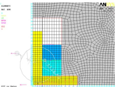
Equivalent circuit model assumes ideal conditions and none of the effects such that reflections, radial and shear mode vibrations are included. Since ceramic rings vibrate in 33 mode, sound speed is assumed to be constant which is not practical. As the thickness become comparable to the lateral dimensions of the rings, sound speed decreases. FEM calculates all these effects and provide more practical results. Using the symmetry of the transducer, 2D FEM model of the back-to-back transducer is constructed with ANSYS as shown in Fig. 9 where only half of the transducer is modeled [4].
Fig. 9 FEM of the back-to-back transducer
Data is extracted from ANSYS and plotted in Matlab [5]. Conductance and susceptance seen at the electrical terminals are given in Fig. 10. The admittance predicted by FEM analysis slightly differs from admittance obtained by equivalent circuit, particularly at the higher end of the frequency range. The lowest radial resonance frequency of the structure is at about 110 kHz. This resonance is not accounted for in the equivalent circuit model, whereas it is considered in FEM analysis. The rise in the conductance values above 85 kHz is due to this effect.
5.
Thermal Analysis of the
Back-to-Back Transducer
Heat characteristics of high power sandwich transducers are also an important consideration. Piezoelectric ceramic rings may generate considerable heat when they are driven at high levels. Electrical power loss in the piezoelectric ceramic ring is given by;
20 30 40 50 60 70 80 90 0 1 2 3 4 5 6x 10 -4 C onducta nce( S ) 20 30 40 50 60 70 80 902 3 4 5 6 7 8 x 10⁻⁴ S usceptance( S ) Frequency(kHz) Conductance-Susceptance Susceptance
Fig. 10 Conductance-Susceptance obtained from ANSYS
Pd =ωE V2 εtanδ
(13) Where ω is angular frequency, Eis the electric field, Vis the volume, ε is the free dielectric constant and tanδ is
the dissipation factor.
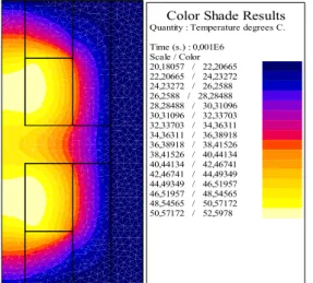
Thermal properties of back-to-back transducer with b=2a are analyzed using Flux2D [6]. We place back-to-back transducer inside an aluminum cylinder whose radius is twice of the transducer and thickness of the aluminum cylinder is 4.5mm. Between the aluminum cylinder and transducer, Loctite 3873 acrylic with thermal conductivity 1.25W/mºK is placed. Thermal conductivity of PZT rings and GRP matching layer are 0.2 W/mºK and 1.8 W/mºK, respectively. Convection coefficient of water is taken as 1350W/m²ºK and outside temperature is assumed to be 20°C. Transducer is driven with 1000Vrms at 80 kHz where tanδ equals to 0.01. At this drive level, average acoustic output power capability, ignoring mechanical losses, is 277W and average electrical power dissipation in four PZT rings is 7.9W. Transient temperature response of the inner surface of PZT rings and steady state response of overall system are given in Fig. 11 and Fig. 12, respectively. Maximum temperature takes place at the inner surface of the rings and the center bolt, as expected, since main path for the heat transfer is steel backing layer and center bolt. The transducer is capable of delivering acoustic power of above 250W where maximum temperature in ceramic rings is 52.6ºC.
Fig. 11 Transient temperature response of the inner surface of PZT rings
6.
Admittance Measurement of the
Back-to-Back Transducer
We have constructed the back-to-back transducer as shown in Fig. 13. Instead of rigid baffle, plastic mount was used for the measurement of admittance. Conductance-susceptance plot from the measured data is plotted as shown in Fig 14. Note that conductance-susceptance values agree well with the theoretical results and %67 bandwidth is achieved around 40 kHz - 80 kHz with a resonance frequency of 60 kHz. The effect of lowest radial resonance of the structure is also visible in the measured admittance values.
Color Shade Results
Quantity : Temperature degrees C. Time (s.) : 0,001E6 Scale / Color 20,18057 / 22,20665 22,20665 / 24,23272 24,23272 / 26,2588 26,2588 / 28,28488 28,28488 / 30,31096 30,31096 / 32,33703 32,33703 / 34,36311 34,36311 / 36,38918 36,38918 / 38,41526 38,41526 / 40,44134 40,44134 / 42,46741 42,46741 / 44,49349 44,49349 / 46,51957 46,51957 / 48,54565 48,54565 / 50,57172 50,57172 / 52,5978
Fig. 12 Steady state temperature response of the overall back-to-back transducer after 1000s
Fig. 13 Constructed back-to-back transducer with plastic baffle. 10 20 30 40 50 60 70 80 90 100 -1 0 1 2 3 4 5 6 7x 10 -4 C onduc tanc e( S ) 10 20 30 40 50 60 70 80 90 1003 4 5 6 7 8 9 10 11 x 10-4 S us cept an ce( S ) Frequency(kHz) Conductance-Susceptance Susceptance
Fig. 14 Conductance-Susceptance obtained from measurement.
7. Conclusion
In this paper, we have shown the design of a half wavelength bi-directional sandwich transducer using two quarter wavelength elements stacked in a back-to-back configuration. Overall transducer operates at frequency range 40 kHz - 80 kHz and has a beamwidth of 60º in each half space. We have analyzed the difference between infinite and finite baffle and showed that infinite baffle assumption would not be appropriate for practical purposes since it neglects all the reflections from the edges.
We have also shown that when the two back-to-back transducers are placed symmetrically around the origin, an omnidirectional beam pattern can be achievable. We have analyzed the far field radiation pattern of this geometry for various combinations of b, a and r, in order to determine the best a and b combination for widest beamwidth in this frequency range.
As a future work, geometry shown in Fig 2 will be constructed. Radiation pattern, frequency response and power handling capability of the overall transducer will be measured.
Acknowledgements
The authors are grateful to A. Sahin and S. Yilmaz for their help with ANSYS, S. Olcum for the sound velocity measurements in GRP, I. Bascuhadar and S. Koklu for their help for the manufacture of the transducer.
References
[1] C.H. Sherman, J.L. Buttler, “Transducers and Arrays for Underwater Sound”, Springer Science-Business
Media, New York. (2007)
[2] T. Mellow, L. Kärkkäinen “On the sound field of an oscillating disk in a finite open and closed circular baffle”, Joint Acoustical Society of America, 118(3), Pt.1(2005)
[3] H. Levine, J. Schwinger, “On the radiation of sound from an unflanged circular pipe”, Phys. Rev. 73 (4) (1948) 383–406.
[4] G. Kossoff, “The Effects of Backing and Matching on the Performance of Piezoelectric Ceramic Transducers”, IEEE Transactions on Sonics and
Ultrasonics, Vol. SU-13, No.1, (1966)
[5] ANSYS, “Piezoelectric Rectangular Strip Under Pure Bending Load”, Release 10.0 Documentation for
ANSYS, VM231.
[6] MathWorks, "MATLAB reference guide (Version 7.5 R2007b)," The MathWorks Inc, Natick, MA, 2007. [7] "FLUX2D Electromagnetic and Thermal Analysis 2-D
Finite Element Program," Magsoft Corporation, Troy, NY.