Makine Teknolojileri Elektronik Dergisi Cilt: 13, No: 3, 2016 (41-54) Electronic Journal of Machine Technologies
Vol: 13, No: 3, 2016 (41-54)
TEKNOLOJİK ARAŞTIRMALAR
www.teknolojikarastirmalar.com e-ISSN:1304-4141
Bu makaleye atıf yapmak için
Türkbaş O.S., Özdemir Z., Akdoğan M.A., “Helikopterlerde Kullanılan Tel Kesme Sisteminin Bilgisayar Destekli Simülasyonu - Alimünyum Tel Üzerine Bir Çalışma”, Makine Teknolojileri Elektronik Dergisi, 2016, 13(3) 41-54
How to cite this article
Türkbaş O.S., Özdemir Z., Akdoğan M.A., “Computer Aided Simulation Of Wire Cutting Systems In Helicopters - A Workout On Aluminium Wire”, Electronic
Journal of Machine Technologies, 2016, 13(3) 41-54
Makale (Article)
Computer Aided Simulation Of Wire Cutting Systems In Helicopters
- A Workout On Aluminium Wire
Osman Selim TÜRKBAŞ1, Zafer ÖZDEMİR*2, Mehmet Akif AKDOĞAN1
1
Gazi Üniversitesi Müh. Mim. Fak. Mak. Müh. Böl., Ankara/TÜRKİYE 2Balıkesir Üniversitesi Müh. Mim. Fak. Mak. Müh. Böl., Balıkesir/TÜRKİYE
*[email protected] (corresponding author) Geliş Tarihi:27.09.2016
Kabul Tarihi:28.10.2016
Abstract
The aerial lines cause great danger for helicopter flying at low altitudes. Twenty five percent of the helicopter accidents originates from wire strikes or crashes to similar obstacles. Therefore, Wire Strike Protection Systems (WSPS) are improved for the helicopters. The performance of a particular WSPS is very important for the flight safety. Prediction of the performance of a WSPS is hard and requires expensive test benches. The utilization of Computer Aided Engineering (CAE) tools would be beneficial in this effort. In this study, the mechanical cutting phenomenon of aluminum cable is analytically investigated and the energy required to cut off the selected cables and wires is analytically evaluated. Beside analytic investigations, a particular WSPS is adapted to a Charpy Impact Test Mechanism. The selected cables and their wires are mounted to the WSPS-adapted-Charpy mechanism and corresponding cutting energies are determined. The simulation of the Charpy tests are performed with the commercial software ABAQUS© 6.6.1. The experimental and numerical results predict similar solutions which implies that CAE tools can be beneficially used in determination of WSPS performance.
Keywords : Wire Cutting, Aluminium Cable, Cutting Energy, Computer Aided Simulation, Abaqus.
Helikopterlerde Kullanılan Tel Kesme Sisteminin Bilgisayar Destekli
Simülasyonu - Alimünyum Tel Üzerine Bir Çalışma
Özet
Havai hatlar düşük irtifada uçan helikopterler için büyük tehlike teşkil etmektedir. Helikopter kazalarının % 25'i tele çarpmalarda veya benzer engeller yüzünden gerçekleşmektedir. Bu sebepten dolayı helkopterler için Tele Çarpayı Önleyici Sistemler (TÇÖS) geliştirilmiştir. Belirli bir TÇÖS'in performansı uçuş güvenliği için bu yüzden çok önemlidir. Sistemin performansını ölçmek zor ve pahalı testler gerektirmektedir. Bu sebepten bilgisayar destekli benzeşim aletlerinden yararlanmak faydalı olabilir.. Bu çalışmada aliminyum kablonun kesilme durumu analitik olarak incelenmiş ve gereken enerji deneysel olarak araştırılmıştır. Aynı zamanda TÇÖS sistemi Charpy Darbe Test Cihazına adapte edilerek kesme enerjileri belirlenmiştir.. Charpy darbe (kesme) testleri simulasyonu ABAQUS© 6.6.1 yazılımı ile gerçekleştirilerek bilgisayar destekli analiz uygulanmıştır. Sonuç olarak deneysel ve numerik analizler benzer sonuçlar göstermiştir. Buradan hareket ile bilgisayar destekli simulasyonunun TÇÖS performansını ölçmede belirleyici olabileceği sonucuna varılmıştır.
42
1. INTRODUCTION:
Due to the advances in aerospace industry, air vehicles have become crucial. Helicopter is one of the most important of these air vehicles. They are practical and do not need wide areas for landing and departure, can even be used in urban areas. They can land and depart on the top of the buildings. They can be used in different areas such as security, search-rescue, military and firefighting [1].
In consequence of extensive and versatile use of helicopters, security problems have come up. Some of the most important of these threats for helicopters are wires in telephone-telegraph and high voltage transmission lines. Especially at flights in urban settlements; at low altitudes; accidents occur because of the crushing to these wires [2-9]. Wire Strike Protection Systems (WSPS) are in use for protection and safety in helicopters. In these systems; wire and cable cutting sysytems have been used to prevent accidents [10-14].
Some research have been conducted about impact analysis by computer aided design on cutting and tearing of metallic elements by some researchers.
Alsos H.S. investigated tearing and clevage process after impact of thin-slender shell metal elements by computer aided simulation and acquired similar results compared with mechanical tests [15]. Wisselink studied the effects of cutting and drilling by means of FEA (Finite Element Analysis) and concluded that most trends in shearing processes are qualitatively well described by the developed shearing models. [16]. Lea and his colleagues investigated the behavior of punched thin metals which were simulated by FEA and the research is part of a more extensive project aimed at the construction of a validated model of the blanking process, the experimental validation and the identification of the material properties (including an appropriate ductile fracture criterion) has been obtained [17]. Hatanaka and colleagues confirmed the results of the finite element simulation, blanking experiments were also carried out using sheet metal of 3mm. thickness under various clearances and for different materials. The experimental results show good agreement with the finite element simulation results [18]. Moesdijk and colleagues revealed that the internal stresses can be transfered into an equivalent load model that can characterize the blanking process. With this equivalent load model the deformed shape of a product after blanking can be determined in a very fast and easy way. Experiments are done to verify the results. Both introduced methods give qualitatively good results [19]. Picart and colleagues have developed a FEM software in order to help to blanking operators to adjust and control the technological parameters of the process and obtain a final part with the desired geometrical and mechanical characteristics [20]. Klingenberg and colleagues have investigated the behaviour of the blank material during the process through finite element simulations, analytical modelling and experimental work. The objective is to contribute towards the development of a system for the on-line characterisation of the blank material properties during the punching/blanking process. The finite element method was applied through the use of ABAQUS code [21]. Kazutake studied on seperation of nodal points at stress test simulation [22] and also shearing simulation test of nodal points [23]. Ko and his colleagues investigated the element disposal method used for piece break off by FEA simulation [24].
Aluminium cables (likely to cause accidents because of crushing of copters) have been subjected to charpy impact tests with a special test apparatus; then a simulation of wire and cable cutting system has been generated and compared with impact tests results in this study.
Impact tests have been carried out according to the EN 10002 and EN 50182. CAD simulation is carried out by ABAQUS© 6.6.1 FEM analysis software.
43
The present study contributes to the literature as a workout on impact (cutting) effect and cutting process on the effect of aluminium cables by means of FEM and CAD. So researchers can benefit from this study for other metals or alloys at different environmental conditions by using computer aided simulations. Hence it can be said that FEM and CAD modelling increase the insight into cutting-impact mechanism and can be used together with experimental research or as a support to the solution of practical problems. This study could enlighten the researchers that mechanical cable cutters could be simulated and analysed with different metals beside aluminium, not only in WSPS area but other scientific areas such as fracture mechanics, impact loading as well.
1.1. Examination of Shearing Force Analytically
The calculation in order to find shearing force is explained below as seen in Figure 1.;
Figure 1. Cutting force in shearing [19]
Fc = A.Kd (eq.1)
[25, 26]. Fc is cutting force, A is the cutting area and Kd is shear strength of material Thus;
A = λs.s (eq.2)
is generated. λs is cutting length and s is the thickness [25,26].
Fkmax = s. λs.Kd (eq.3)
Kd = FKmax / s. λs (eq.4)
is obtained [25].
We can correlate the maximum strength of material with the shear strength (Kd ). From here;
C1= Kd / ơmax (eq.5)
could be obtained [25,26].
C1 could be at the interval; 0,6<C1<0,95. Advised value is 0,8 - 0,95 for C1 [25,26]. From here;
Kd = 0,8. ơmax (eq.6)
44
1.2. Configuring Cutting Energy
There is 3 kinds of energy; elastic deformation, plastic deformation and cleavage energy as shown in below;
Ek = Ee + Ep + Ec [27]; (eq.7)
dE = F.dλ (eq.8)
Figure 2. Cutting energy graph [25]
Ec = 𝐹𝑐 𝑥 . 𝑑𝑥0𝑥 (eq.9)
Taking the integral [25];
Ec = C.x.FCmax (eq.10)
is concluded as seen in Figure 2.
2. MATERIALS AND METHOD
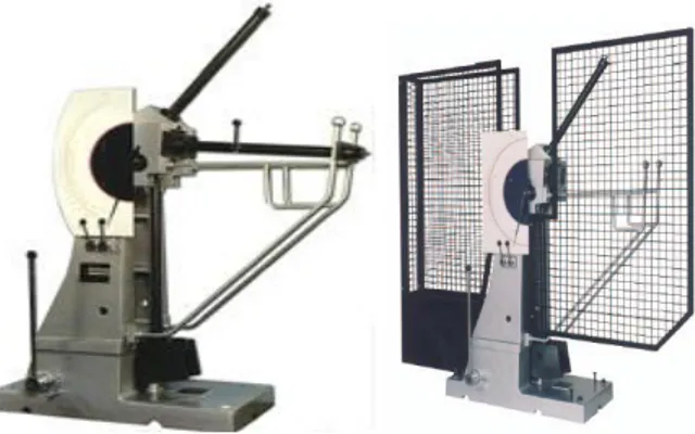
Charpy impact tests have been carried out by mechanism shown in figure 3. An additional apparatus have been mounted to the mechanism in order to carry out cutting process as shown in figure 4.
Figure 3. MAT 21 model , Adapted Charpy Impact Test Mechanism for a particular WSPS
to carry out cutting process
45
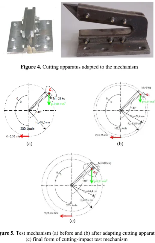
Figure 4. Cutting apparatus adapted to the mechanism
(a) (b)
(c)
Figure 5. Test mechanism (a) before and (b) after adapting cutting apparatus
(c) final form of cutting-impact test mechanism
As a result of the modification of the test device, some changes occur at the energy levels as seen in figure 5.
46
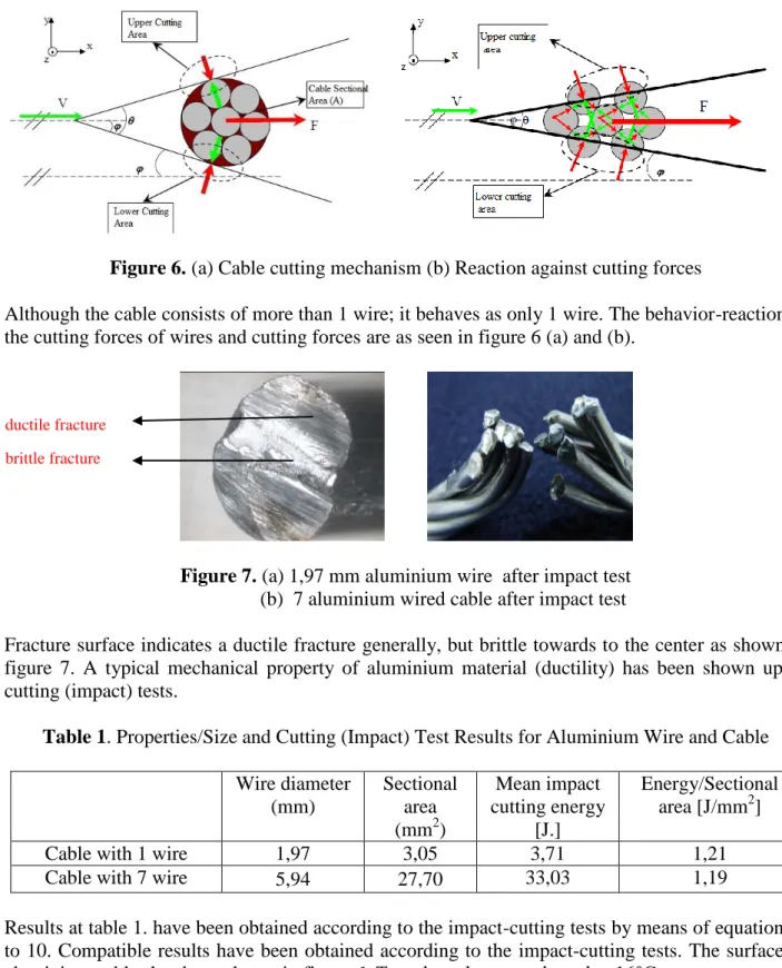
Figure 6. (a) Cable cutting mechanism (b) Reaction against cutting forces
Although the cable consists of more than 1 wire; it behaves as only 1 wire. The behavior-reaction to the cutting forces of wires and cutting forces are as seen in figure 6 (a) and (b).
Figure 7. (a) 1,97 mm aluminium wire after impact test
(b) 7 aluminium wired cable after impact test
Fracture surface indicates a ductile fracture generally, but brittle towards to the center as shown in figure 7. A typical mechanical property of aluminium material (ductility) has been shown up in cutting (impact) tests.
Table 1. Properties/Size and Cutting (Impact) Test Results for Aluminium Wire and Cable
Wire diameter (mm) Sectional area (mm2) Mean impact cutting energy [J.] Energy/Sectional area [J/mm2]
Cable with 1 wire 1,97 3,05 3,71 1,21
Cable with 7 wire 5,94 27,70 33,03 1,19
Results at table 1. have been obtained according to the impact-cutting tests by means of equations 1 to 10. Compatible results have been obtained according to the impact-cutting tests. The surface of aluminium cables has been shown in figure 6. Tests have been conducted at 16°C.
Selected aluminium properties have been shown at table 2.
Table 2. Material properties of aluminium 2011
Density (g/mm3) Elasticity Modulus (MPa)x103 Shearing Modulus (MPa)x103 Poisson Rate Yield Strength (MPa) Maximum Strength (MPa) Hardness (Brinell) Cutting Strength (kgf/mm2) 2,71 70 26 0,33 298 380 45 12 ductile fracture brittle fracture
47
3. COMPUTER AIDED DESIGN MODELLING
All the studies so far have been conducted in real situation in order to release some experimental data via impact-cutting tests. The following studies are computer aided design modelling in same situations to compare the impact test results and CAD.
The subject studied on is very dynamic and fast, so static and analytical approaches remain incapable. For that reason, computer aided modelling has been used and compared with impact-cutting tests for aluminium cables. This modelling approach could be useful for other materials such as copper and alloyed steel.
ABAQUS© 6.6.1 software has been used for CAD modelling. ABAQUS software, as a reliable method, contributes to study on a complex mounting mechanism, to understand a conceptual design and to model a complex manufacturing process.
3.1. Solid modelling for CAD
Solid model of cutter was composed at CAD, then was imported to ABAQUS© 6.6.1. software. Solid model has been created for 6 main pieces as shown in Figure 8. (a) and (b) in ABAQUS© 6.6.1 and then assembled in same software.
(a) (b)
Figure 8. Cutter assembly; a) Solid model (linear), b) Solid model (full)
Cable's solid model has been created in 2 ways. First as a single wire; 1 meter and 5 mm. diameter, second 7 wire with each diameter 2,36 mm., 1 meter and making a pitch in each 130 mm. and bended on each other so as to make a one cable. It is shown in Figure 9.
(a) (b)
48
3.2. Composing Finite Element Model
The model for cable (7 wires system) and cutting system have been created respectively as seen in figure 10,11 and 12.
Figure 10. Rigid model of cutting surfaces
Figure 11. 7 wired cable a) Solid model b) FEA model
Figure 12. Wire a) Solid model b) FEA model
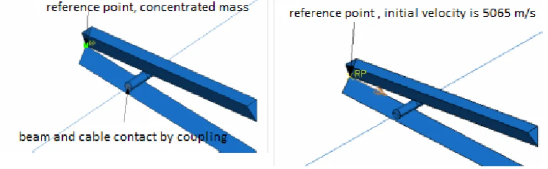
Reference point (RP) on the wire cutting tool and boundry conditions of aluminium cable have been indicated in figure 13. The aim of CAD is to make a similar model of charpy impact test. Hence, a mass of 20,5 kg or 0,0205 ton point mass has been defined. RP is allowed to make reciprocating motion only through 1 axis direction, but not rotational motion. No motion (reciprocating and rotating) through 2 and 3 axis directions are not allowed in order to get reliable results. In charpy impact test; at the junction of wire cutting system and cable only reciprocating motion is conducted. The same velocity (5,065 m/s) value at the charpy impact test is taken for CAD modelling. Boundry conditions for both impact-cutting test and CAD modelling is shown table 3.
49
(a) (b)
(c)
Figure 13. Cutter and cable boundry conditions;
a) Connecting mass and mass-cable relation ascribed to the reference point b) Initial velocity of reference point
c) Boundry conditions for cable edges and cutter.
Table 3. Boundry conditions for impact tests (experiment) and computer aided analysis
CUTTER CABLE
Displacement Rotate Displacement Rotate
Experiment Axis 1 Free None None None
Axis 2 None None None Free
Axis 3 None None None None
Model Axis 1 Free None None None
Axis 2 None None None None
Axis 3 None None None None
CAD is composed by determining rigid cutter model and cable respectively.
3.2. Analysis results
All wires (1,97 mm., 2,39 mm., 3,5 mm., 4,26 mm. and 5 mm.) and cable have been analysed both by impact tests and CAD. The CAD results and images have been submitted below through figure 14-16. The comparison between impact-cutting tests and CAD modelling is shown in table 4.
50
51
Figure 15. Cutting stages of 5 mm. Aluminium wire
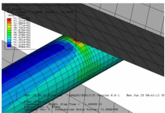
Figure 16. Pressure distribution of on aluminium wire just during cutting
Distribution of stress is homogeneous and consistent as seen in figure 15 and 16. Hence it can be said that a succesful simulation has been processed. Also range of deviation between experiment and simulation results is acceptable.
Table 4. Comparison of test and CAD results
Materi al Diamet er (mm) Kinetic energy in CAD without friction (Joule) Friction coefficient Kinetic energy in CAD with friction
(Joule) Kinetic energy in impact tests (Joule) Deviation % Al 1,97 1,1 0,3 3,66 3,71 1 2,39 1,4 0,3 4,67 5,66 21 3,5 4,5 0,3 15 12,7 18 4,26 5,1 0,3 17 13,81 23 5 8,4 0,3 28 32 14
As it is seen obviously at the simulation via FEM and CAD, the results of impact-cutting tests (table 4.) and simulation findings are compatible with each other. The contact surface takes the initial force (figure 14.) and stress distribution is an impact force distrubition rather than continuous cutting. Pressure distribution shows a cutting-impact behaviour composition as seen in figure 15 and 16.
52
5. DISCUSSION
The impact-cutting tests for WSPS systems have been carried out for Aluminium wires (5 different diameters) and cable (7 wired cable). Totally 30 impact tests have been carried out and CAD modelling has been performed for Aluminium wires. 5 mm. wire Aluminium CAD simulation via ABAQUS software has been presented.
From the simulation results and the comparison with experimental results can be concluded that most trends are well predicted by the simulations, but that quantitative differences between simulations and experiments are found ( table 4.). The main reasons for the differences between simulations and experiments are the coarse finite element mesh in the 3D simulations.
An apparatus adaption to the impact test device for cutting contributes the study an originality. The study consists of 3 main step; analytic-experimental-CAD simulation. This is also very remarkable for this research.
Although generally a ductile fracture has been observed, to the inside surface, brittle fracture could be seen . This is also remarkable because this shows us how cutting-impact phenomenon explains fracture and cleavage.
As the wire number increases, the energy required for fracture increases. Also stress distribution in the simulation shows us a proportional and consistant cleavage.
The tests and simulation could be done at lower temperatures to obtain other valuable findings. This could enlighten researchers for motivation.
When the cutting surfaces have been investigated, it is a ductile fracture-failure. In the CAD simulation the cutting time has been calculated between 0,008-0,02 s. Time interval is almost same as the cutting tests. The cutting energy values in CAD simulation deviates from impact-cutting tests approximately % 20 as shown in table 4. For us; this value (% 16) shows the success of simulation, because it is a reasonable result. The reason for the deviation is; the CAD simulation has been done in ideal circumstances (no gravity and friction) and but the impact-cutting tests have been carried out on with an adapted test mechanism. Not exactly the same conditions have been obtained, but results are compatible with each other. As the wire number increase, deviation between simulation and tests remain almost same. Only for 1,97 mm. the deviation is % 1. The other wires average deviation values are approximately % 16.
Previous studies literature [especially 15,16,17,18,19,] proves a compatibility between test results and simulation. This study also exposes compatibility; with one difference. The difference is an additional apparatus has been adapted to the charpy test mechanism. So the test became an impact-cutting experiment.
6. CONCLUSION
The current study reveals the following results ;
1. A combination of analytical, experimental and CAD simulation has been carried out in this workout. All of them are compatible with each other.
2. The CAD simulation could be an effective analytical method for solving different kinds of wires for example copper and steel for WSPS.
3. A new perspective could be obtained by CAD simulation for also tensile and compression tests of wires.
4. The tests and simulation could be done at lower temperatures to obtain distinctive findings. 5. The simulation could be used as an alternative to the practical usage, but should be reinforced and verified with the test-experiment results.
53
7. REFERENCES
1. Johnson, W., "Helikopter Theory", Princeton University Press, New Jersey, 11-20 (1980). 2. Tuomela, C.H., Brennan M.F., "Civil Helicopter Wire Strike Assessment Study", HumRRO
FR-MTR(CA)-80-13, Virginia, 1:1-58 (1980).
3. Doughty, L., "Wire Strikes", Aviation Safety Vortex, 9:1-4 (1989).
4. Australian Transport Safety Bureau, "Bell 206B, VH-CSH Dunedoo, NSW, ATSB - 200404590, Australian, 1-61 (2003).
5. Polkinghorne, A., "Powerlines are the number one hazard for low-flying helicopters", Flight Safety, Australlia, 34-35 (2005).
6. Walker, M., White, S., "Wire Strike", Flight Safety Australia, July-August 1999, 37-38 (1999). 7. The Transportation Safety Board of Canada, "Wirestrike" TSB-A95A0040, Canada, 1-14
(1995).
8. Harris, J.S., "Data Show 50 U.S.-registered Helicopters involved in Wire-strike Accident From 1996 Through 2000" Flight Safety Foundation Helicopter Safety, 28 (4):1-6 (2002).
9. ARMY Aviation Risk-Management Information, "Tree strikes, you are out!", Flightfax, http://safety.army.mil, 27 (6):1-12 (1999).
10. Jackson, K.E., Boitnott, R.L., Fasanella, E.L., "A History of Full-Scale Aircraft and Rotorcraft Crash Testing and Simulation at NASA Langley Research Center", U.S. Army Research Laboratory, VA, 1-22 (2003).
11. Jackson, K.E., Fasanella, E.L., "A survey of research performed at NASA Langley research cebter's impact dynamics research facility", American Institute of Aeronautics and Astronautics, U.S. Army Research Laboratory, VA, 1-19 (2003).
12. Jackson, K.E., Boitnott, R.L., Fasanella, E.L., "A Summary of DOD-Sponsored Research Performed at NASA Langley's Impact Dynamics Research Facility", U.S. Army Research Laboratory, VA,1-13 (2003).
13. Burrows, L.T., "Investigation of Helikopter Wire Strike Protection Conceps", USAAVRADCOM-TM-8D-7, U.S. Army Applied Technology Laboratory, Ft. Eustis, VA, 1-2 (1980).
14. Burrows, L.T., "Verification Testing of a UH-1 Wire Srike Protection System (WSPS)", USAAVRADCOM-TR-82-D-35, U.S. Army Applied Technology Laboratory, Ft. Eustis, VA, 1-2 (1982).
15. Alsos, H.S., "A Comparative Study on Shell Element Deletion and Element Splitting", Massachusetts Institute of Technology, Report No:127, Massachusetts, 1-94 (2004).
16. Wisselink, H., "Analysis of Guillotining and Slitting, Finite Element Simulations", Doktora Tezi, University of Twente, The Netherlands, (1-146000).
54
17. Lee, T.C., Chan, L.C., Zheng, P.F., "Application of the Finite-Element Deformation Method in The Fine Blanking Process", Journal of Materials Processing Technology, 63:744-749 (1997). 18. Hatanaka, N., Yamaguchi, K., Takakura, N., Takasi, I., "Simulation of sheared edge formation process in blanking of sheet metals", Journal of Materials Processing Technology, 140:628-634 (2003).
19. Moesdijk, R.D.V., Wisselink, H.H., Boogaard, A.H.V., Huetink, J., Bolt, P.J., Sillenkens, W.H., "Blanking by Means of the Finite Element Method", Computational Mechanics, Barcelona, 1-13 (1998).
20. Picart, P., Lemiale, V., Touache, A., Chambert, J., "Numerical Simulation of the sheet metal Blanking Process", VIII International Conference on Computational Plasticity, Barcelona, 1-4 (2005).
21. Klingenberg, W., Singh, U.P., "Finite element simulation of the punching/blanking process using in-process characterisation of mild steel", Journal of Materials Processing Technology, 134:296-302 (2003).
22. Komori, K., "Simulation of tensile test by node separation method", Journal of Materials Processing Technology, 125-126:608-612 (2002).
23. Komori, K., "Simulation of shearing by node separation method", Computers and Structures, 79:197-207 (2001).
24. Ko, D.C., Kim, B.M., Choi, J.C., "Finite-element simulation of the shear process using the element-kill method", Journal of Materials Processing Technology, 72:129-140 (1997). 25. Klocke, F., "Fine Blanking", WZL RWTH AACHEN, Germany, 5:1-32 (2005).
26. Behrens, B.A., Schaeper, E., "New shearing technique with adjustable blade clearance and online blade clearance control", Universität Hannover-Produktionstechnisches Zentrum-Schönebecker Alle 2 - D-30823 Garbsen, 1-10 (2003).
27. Ulbricht, V., Franeck, J., Schirmacher, F., Offermann, P., "Numerical Investigations for Cutting of Wires and Threads", AUTEX Research Journal, 3(1):9-15 (2003).
![Figure 1. Cutting force in shearing [19]](https://thumb-eu.123doks.com/thumbv2/9libnet/5828209.119318/3.892.257.639.366.550/figure-cutting-force-in-shearing.webp)