DESIGN AND IMPLEMENTATION
OF A TOOL FOR
TEACHING
PROGRAMMING
MESUT G~KTEPE, B~LENT &ZG~~C and MEHMET BARAY
Department of Computer Engineering and Information Sciences, Bilkent University, P.O. Box 8, 06572 Maltepe, Ankara, Turkey
(Received 23 &fur& 1988; ret,+.& 20 Jufy 1988)
Abstract-Recently, computers have been widely used in almost all fields of education. Our approach to computer aided education is mainly concerned with programming. Here, it is intended to teach the Pascai language for problem solving in a visual manner. In this project, we have used an object oriented approach for the implementation of an educational tool for programming. The paper mainly discusses the topics related to computer aided education, user interface, object oriented programming and ongoing research related to the project.
USING COMPUTERS FOR EDUCATION
It appears to be a common idea that computers widen the learning environment, extend the range of messages, provide immediate &es, feedback, and corrections necessary for learning. In the worId of education, the computer appears not as a substitute for the teacher but instead as an assistant taking over routine chores expected of the teacher.
Computer based teaching strategies{11 can be classified as: l drill and practice
l dialogues 0 simulation 0 games 0 testing l probIem solving l discovery learning
Drill and practice
Drill and practice as an education strategy promotes the acquisition of knowledge or skill through repetitive practice. In computer assisted instruction, drill and practice usually refer to small tasks such as the memorization of spelling of vocabulary or practicing of arithmetic facts.
Dialogue
The dialogue approach to computer assisted instruction tries to emulate a dialogue between a teacher and a student. Therefore the computer, in effect, holds the information that the student must learn through some type of interaction. This interaction is twofotd, one, a computer controlled dialogue (tutorials) in which the computer asks the student questions, the other, learner controlled dialogues in which the student makes inquiries of the computer.
Simulation is the controtled representation of real world phenomena. Simulations may be particufarIy appropriate when the real experience is too costly or awkward to provide, or when an element of risk is involved. Task performance, system modelling, and experience/encounter simulations may all be referred to as instructional simulations.
Games
A game is a goal oriented activity that can be completed successfully by the skillful application of a set of rules. Instructional games are those whose content and process closely relate to some instructional objective or benefit, such as word or vocabulary games.
168 MLSUT G~KTEPE et ai Computer assisted testing
A computer assisted testing system has the testing cycle of: l test construction
l test delivery
l grading and analysis 0 item analysis
l item storage for feedback in the next test for evaluating the performance of an entity.
Problem solving
In many academic disciphnes the major instructional objective is the development of students’ ability to formulate and solve problems. Problem solving with computers uses the same method of problem solving as other means. The computer is simply a tool that users must learn to manipulate in the same way as other tools to obtain the solution to a problem with a correct result.
Discovery learning is a strategy in which educators provide the student with tooIs for exploring, analyzing, and mastering new concepts and principles in a structured way.
We can now combine some of these strategies to present a tool for teaching programming.
COMPUTER AIDED EDUCATION FOR PROGRAMMING
At this stage, a combination of computer based teaching strategies can be applied to teaching programming.
Once the problem that requires a solution by computer is analyzed in detail, the most important step follows, the selection of the best algorithm. Derivation of the flowchart for the algorithm comes next. These steps lead to an efficient and correct program for solving the problem. An algorithm gives the logical steps of a program in textual form so that a program can be generated from it; the flowchart presents the same information graphically.
The structure of a program is derived by dividing the problem into logically complete blocks- subproblems-and analyzing each separately, After defining the structure, the code for the program can be written easily; ideally through a structured language.
Pascal facilitates writing structured programs; programs that are relatively easy to read, under- stand, manipulate, and maintain. It is currently one of the most widely used languages for teaching programming. Its popularity is due to the fact that its syntax is relatively easy to learn.
The goal of structured programming is to organize and discipline the program design and coding process in order to prevent most logic errors and to detect those that remain.
Structured programming concentrates one one of the most error-prone factors of programming, the logic. It has three major characteristics:
l top-down design o modular programming l structured coding
In top-down design, first the program is specified in the broadest outline and then the structure is gradually refined to fill in the details. In each step a given task is broken down into a number of subtasks until the subtasks are simple enough to be coded with a highly reliable process of programming. Modular programming is the process of dividing a program into logical parts called modules and then successively programming each part. Here the size of the modules must not be too large and each module must be independent of the others. Structured coding is a method of writing programs with a high degree of structure providing for understandable programs for testing, maintenance and manipulation. Any proper program- a program with one entry and one exit point and no infinite loops or unreachable code---can be accomplished only by the logic structures of:
__.f---f___ j--/__
Fig. I. BEGIN-process-END.
l a sequence of two or more operations as in Fig. 1 l the selection of one or two operations as in Fig. 2
l iteration of an operation when a condition is true as in Fig. 3
Pascal is a structured language facilitating the mentioned characteristics of structured pro-
gramming. It has BEGIN-END blocks, PROCEDURES, and FUNCTIONS providing constructs
for modular programming. Pascal executes the code from top to bottom in sequence, enabling the sequential processing. IF-THEN-ELSE, and CASE statements facilitate a selection mechanism for structured programming. For a tool for teaching programming the language is selected to be PASCAL for the reasons listed above[2].
In order to satisfy user needs in a simple way, we have to present the application in such a friendly manner that the user need not spend too much time in learning the system itself, but instead can play with it while learning programming in Pascal. This is accomplished best by means of user-friendly tools.
USER-FRIENDLY TOOLS
User interface
As the sophistication of computer systems increase with technology, the requirement for computers to remain friendly, comprehensible, and effective to continue to appeal to users also increases. A crucial factor in all three of these attributes is the quality of communication between user and machine.
The user interface is the part of the program that determines how the user and the computer communicate. The design of interactive user interfaces is very important for the performance of the application. Not only are bad user interfaces difficult to Ieam, but they make programs difficult to use even in the hands of experienced users.
For the naive user, graphical interfaces have now been introduced that represent a significant improvement over traditional command languages as a means of realizing the full potential of a computer. As an example, iconic interfaces present command and system information in a non- verbal manner, i.e. in the form of icons by which the learning curve can be reduced in both time and effort. Thus, it improves user performance while reducing errors. The reason for upgrading the user interface and thus performance in this manner follows the argument that communicating through images is the most natural way of communication. Furthermore, images can be easily recognized and learned, and thus may be better than their lexical equivalents[3].
Generally any graphicaf user interface is composed of two parts, the presentation part and the interaction part. The presentation or iayout part defines what pictures are on the screen, i.e. placing graphics and images on various parts of the screen. The interactions or behaviour part determines how these pictures change with user actions i.e., transfo~ing an object on the screen.
170 MEWT G~KTEPE et ~1
Models of the user interface can be considered to fall into two broad categories: linguistic models, and spatial models. Linguistic models view the interface as a dialogue between user and computer,
and focus on issues that occur within the semantic, syntactic, and lexical levels of the dialogue. Spatial models include interactive graphics or direct manipulation models. A well designed user interface normally incorporates both linguistic and spatial components[4].
User interface components[5] naturally can be grouped into four:
The user’s model. This is a conceptual model acting as a framework for the development of strategies for operating the program. It enables the user to have a broad understanding of what the program is doing. The use of familiar concepts makes the user’s model more intuitive and easier to learn. It is difficult to gain acceptance for a program that presents the user with unfamiliar objects that behave in highly unexpected ways.
Command language. Once the model is understood the user needs commands to manipulate it, a system of which forms a command language. Principal issues of command languages are command modes, selection sequence, a command abort mechanism and error handling. Command modes are the states in which a given operation by the user is interpreted differently by the program. Selection sequence is the order to manipulate a command. Command abort mechanism is necessary to disable a currently working command. An error handling mechanism is how a program must respond to incorrect input.
Feedback. Feedback is a component of the user interface through which the computer assists the user in operating the program. Some forms of feedback are provided only for naive users, and ignored by experienced users. Acknowledgement of reception of commands, explanatory messages, indication of selected objects, echoing of typed characters are some forms of feedback that help the user to be informed about the correct receipt of his commands.
informarion display. This component shows the user the state of the information he is manipulat- ing. By means of well chosen symbols and graphics, the user can be given confirmation that his model is correct. ‘For a more effective utilization of the screen for information display, the way menus, windows, informative icons or graphics are handled, together with selection mechanisms, must be taken care of properly. A device independent user interface that functions with a wide variety of devices is the most feasible design issue for a user interface, since it provides for applica- tions to be portable from one hardware configuration to another. On the other hand, such a design is quite difficult and the results might not be equally satisfactory for all classes of devices. In the following sections, implementation details are given for the topics discussed above.
Tools for user interface
In current user friendly systems, the hardware environment for applications generally consists of a high resolution bit addressable screen, a small pointing device called a mouse, and multitasking capabilities. On a single screen, multiple overlapped windows can be concurrently active and each window can contain multiple special purpose subwindows, each of which can have an active process. A wide variety of subwindow types provides for easy development of user interfaces.
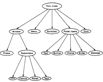
In such a system, management of the common interface functions is provided by a notifier and selection service, a window manager, and a broadcast service. The notifier and selection service are the runtime systems distributing input to the appropriate windows. The window manager manages the overlapping windows. The broadcast service makes it possible to activate tasks and exchange data between applications running in separate windows in the same or in different processes[6]. Such a notifier based system running in a multiple window environment contains various tools and actions for the user interface. A tool is a software entity providing a functional interface and is manipulated by passing its unique identifier, called a handle, to its associated functions. Classes of these tools are defined in a hierarchy and can contain subclasses that may inherit common behaviour from their superclass. For a window manager system[7] this class hierarchy can be represented as in Fig. 4.
Here we have used the terminology of SunView r”* (Sun Visual/Integrated Environment for Workstations)[7] to describe the elements of a window manager.
Fig. 4. Class hierarchy of a window manager system.
Windows. Windows refer to a visible component of the display that the user perceives as a single entity-tool-and manipulates as a unit.
Frames. Frames are windows containing nonoverlapping subwindows within their borders with
the purpose of bringing different types of subwindows together into a common framework, providing them to be operated on as a single unit.
~~~wjndo~s. Subwindows are windows which never exist inde~ndently and are always owned
by a frame.
l Panel: A panel is a subwindow containing panel items of buttons, message items, choice items,
text items, or sliders. Buttons are simple activation confirmation items, message items provide an output area, choice items are to select among a number of items, text items present a type-in area, and sliders are to provide a continuous range of values.
l Text: text is a subwindow with capabilities for editing text.
l Canvas: A canvas is a subwindow into which programs can draw.
l my: A TTY is a subwindow in which programs can be run and commands can be given. Panel items. Panel items are panel components facilitating a particular interaction between the user and the application by button, message, slider, and choice items.
Scrollbars. Scrollbars are lower class and dependent elements that may be attached to a
subwindow to control the display of the specified portion of the window by sending appropriate locational messages. Another name used for scrollbars is the elevator.
Menus. Menus are special purpose subwindows allowing the user to choose from a list of actions. Icons. Icons are small images symbolizing an application or its state.
These tools support the design of the style of user interfaces where the user typically uses a mouse to select and manipulate objects on the screen[7-91.
A window is activated when a user points to it say for input, and the window generates an event. Therefore events and their notification becomes a significant part of such a system.
A notification bused system
Having a multiplicity of independent input sources, control of flow has to be taken away from the application, i.e. without performing input and output explicitly, the application must register interest, describing the routines it wishes to be called when certain input/output events occur. A notifier is an example of this approach. Thus, notification based systems have some characteristics rather opposite to those of conventional sequential programming systems. In a notification based
172 MESGT G~KTEPE es al.
I
START I Collbock procedure 1 f Return to opplicotion Fig. 5. Control structure of a notifier based system.system, the main control loop of the application does not reside in the application itseIf but it is managed by the concurrent notifier that is the controlling entity for user processes. The duty of the notifier is to sense the events and activate the procedures of the applications-described as callback procedures-already specified for the events, An event is almost anything that is prescribed. The functions to be activated by the occurrence of an event for an apphcation are registered with the notifier. This registration process is provided through specification ofcallback procedures for events (741.
The control structure of a notifier based program is given in Fig. 5.
Without a centralized notifier, the application itself would have to carry the duty of detection and dispatching of events to its components as in the case of conventional interactive programming. But the existence of a centralized notifier provides for each function to receive only the events related to itself.
Therefore, in a noti~cation based system, the programmer creates the required functions and tool definitions for the application, then registers such definitions with the notifier, based on the occurrence of a class of events. The control is then passed to the notifier/selection mechanism and if an event from the prescribed class should occur, the selection service activates the necessary tools(6,7].
As will be the case in our application, sometimes two processes need to communicate with each other, say, to share common data. As an example, a process running in a window may want the
data generated by the process running in the next window. This communication can be accomplished by facilities provided in the operating system of the computer.
Communication processes
Operating systems do have some means to facilitate the communication of processes with each other. A process is simply a program in execution. A process may be informed of an exceptional condition-perhaps by another process-by means of a signal. The function of pipes is to provide a unidirectional data flow between processes. A true interprocess communication and networking may be accomplished by use of sockets[lO].
Signals. Many applications accomplish their tasks in isolated processes, but some require interprocess communication (IPC). Signals are not interprocess communication in any usual sense, but facilitate the handling of exceptional conditions. Various events such as terminal break, or program error are reported to a program via an asynchronous signal.
There are a number of signals, each one corresponding to a specific condition. Examples are an interrupt from the keyboard, an error in a process, a number of asynchronous events such as job control signals or timer generated signals.
An interrupt signal is used to stop a command before it would otherwise be completed. The quit signal has the same effect except that it writes its current memory image to a file. Stop/Restart signals are used to stop and restart a process in job control, while a kill signal kills a runaway process. An illegal instruction and an attempt to address memory outside the legal virtual memory space of a process also generate signals.
Pipes. A pipe is simply a connection between the standard output of one program and the standard input of another program. Data can be sent properly between two processes via an interprocess channel called a pipe. The pipe is the most characteristic interprocess communication mechanism of operating systems modelled on Unix. A pipe permits a reliable unidirectional byte stream between two processes. Communication through bidirectional data flow between processes can be facilitated by a socket mechanism.
Sockets. A socket mechanism provides a general interface, not only to facilities such as pipes which are local to one machine, but also to networking facilities.
A socket is an end point of communication having an address bound to it when in use. The nature of the address depends on the communication domain of the socket such that processes commu- nicating in the same domain use the same address format (e.g. Unix domain, Internet domain). A single socket ordinarily communicates in only one domain.
Several existing types of socket represent classes of service. Stream sockets provide reliable duplex sequenced data streams. Datagram sockets transfer messages of variable size in either directions. Reliable delivered message sockets would transfer messages that would be guaranteed to arrive.
As will be discussed in later sections in more detail, during the implementation we intended to use only pipes and signals for communication of multiple processes: pipes, since data flow would be unidirectional from one process to the other, and signals, for confirmation of receipt of data.
The window and selection/notification management, together with message broadcast or
reception, can be handled most suitably in a software development environment known as object oriented programming. Some basic concepts of this environment together with certain application details of the Tool for Teaching Programming will be explained in the following sections.
Object oriented programming
The object paradigm provides a natural mechanism for representing a system at several levels of abstractions from a very low level concept, such as a number, to a very high level concept, such as an office information system. Graphical applications, data base applications, and user interface design are the main areas where object oriented programming techniques have been widely used recently. The innovative work of Kay and Goldberg at Xerox corporation in developing objects for
the Smalltalk language obviously contributed much towards the advancements of these
techniquesI 1 l-l 31. A few other languages have such capabilities. Objects in C are a recent addition that this project makes use of mostly as an extension to the toolkit on which the code is built[7].
I74 MESUT G~KTEPE er al.
Object oriented programming differs from traditional control oriented programming in that al1 conceptual entities are modelled with a single concept, an object. An object is an entity with attributes and having relationships with other objects.
Temperature range, size, danger level, color can be the attributes of an object representing a temperature gauge. The identity of an alarm object could be the value of a relationship. Methods are a kind of procedure in which the behaviour of an object is embodied. The method for a temperature gauge coufd be the display of a temperature dial by graphics routines.
A message is the s~cification of an operation to be performed on an object, similar to a procedure catl. Messages provide for objects to communicate with other objects to request info~ation or some form of behaviour from them, for example a temperature gauge can be requested to display itself by messages from other objects. A method for an object is a function that implements the response when a message is sent to that object. An object reacts to a message by executing its corresponding method, which is a piece of code manipulating or returning the state of the object.
Objects can be represented in a class hierarchy inheriting properties down the hierarchy. Therefore different classes of object can be defined, each object being an instance of a cfass. A class describes the form of its instances and operations applicable to its instances. Objects of the similar type are grouped into the same class. An object differs from other instances of the same class by the value of its attributes and relationships, but all the instances have the same methods of the class. Lower down the class hierarchy, a class can also have subclasses as well as objects (instances of the class). All subclasses of a class inherit the properties of its superclass and additionally have its local propertiesf14,15].
As an example, a class for graphical objects can be defined as: Class: graphic-object
Attributes: list-of-coordinates, line-style, text-info, text-font, color
Relationships: list-of-graphic-objects Methods: display, erase, transform Messages: none
In the example, object hierarchies can be built from the graphic-object class as a list of graphic objects through reIationships. When a message is sent to a graphic object, the method implementing that message is found in the class definition of the graphic object. A graphic-object from the above class responds to messages to perform its methods but does not generate messages itself[4].
An object oriented system for the construction of a window based user interface consists of a set of objects and actions for the interface. Objects present a functional interface and are manipulated by passing their unique identifier to their associated functions.
Tools for the user interface described previousiy comprise a system of objects. Figure 4 shows the class hierarchy for such an object oriented system. The methods of manipulating these objects in an application are the callback procedures registered with the notifier.
In an object oriented window manager system each clement of the window manager belongs to a basic class object. Window is a subclass of object class having frame as an object and subwindow as a subclass. TTY, canuas, panel and text are the objects of subwindow. Additionally, text, button. message, choice and slider are the objects of panel items subclass belonging to object ciass. Also, menu, scrollbar, and icon are the objects of object class{7].
While developing our object oriented education tool, we have used the window manager’s own objects in addition to the objects designed specifically for our application.
The main concepts of object oriented systems[l6] can be summarized as:
l Data abstraction: In object oriented systems, the interest of the user is concerned with the
behaviour of an object rather than its representation, and the behaviour of an object is defined by its methods.
l Independence: The control of an object’s state and its existence is provided by the object itself.
An object’s methods are the only interface to its state. The ability to add new types of objects at run time can also be an independence concept in object oriented programming.
l Messagepass~ng: Communication of objects is only possible by the message passing paradigm.
The only way for one object to interact with other objects is by sending messages to invoke their methods.
l Inheritance: A subtype in the hierarchy of objects inherits the properties of its parent type, possibly adding some local properties.
l Homogeneity: In a fully object oriented system, everything is an object and objects are the active entities.
All the concepts discussed so far constitute a framework for our research. Our tool for reaching programming has been developing under sections related to education, object oriented pro- gramming, communication processes, and user interface. Now, our research can be presented with this as a background.
RESEARCH
The purpose of the research is the design and implementation of a toolfor teaching programming in Pascal language.
The environment for the research is a workstation with multitasking capabilities, the C pro- gramming language, and a revised object oriented window manager system to support interactive, graphics based applications running within windows.
Graphics architecture
Graphics architecture for the application is based on raster graphics. In raster graphics every visible picture element on the screen is called a pixel and has a corresponding storage location in memory. In workstations, display rasters are stored in dedicated regions of memory called frame buffers or video memory. A high speed frame buffer offers flexibility for the display of arbitrary objects, including variable width characters, foreign alphabets, mathematical symbols, lines, curves, shaded regions, and photographic images.
A frame buffer is generally organized by plane used for monochrome applications, mapping one bit of memory to one pixel. Also a frame buffer may feature additional raster operation hardware to speed up raster operations[9,17].
A tool for teaching programming in Pascal
The tool provides the user with a means to draw a program flowchart in a window through a menu of icons and commands, then displays the corresponding Pascal code of the flowchart through the directives from the user with the help of a pointing device, a mouse. An early work for constructing algorithms through a graphical tool has been discussed by Goldberg[l8]. There are a few other projects that use graphical tools for the development of various forms of mechanical languages, simulation models, critical path analysis, etc. The approach discussed here develops a complete Pascal code through the use of objects most of which are graphical; furthermore, the code can be compiled and interactively executed in the same environment. In essence, the compiled code behaves almost like a new object with respect to the global environment and a simple Pascal program with respect to the user running it.
Flowchart elements are picked from a menu containing flowchart symbols as icons and are drawn on the graphic screen. The text information of each symbol is filled in by selection of a text entry command from the menu (Fig. 6).
As for the naming conventions of the tool, flowchart symbols are named in two categories: boxes and arcs.
A bo_\: is a flowchart symbol representing an action or process in the chart and may contain text information in it. An arc is the flowchart symbol providing a means of connecting the boxes of a flowchart, in other words an arrow.
Boxes have connection points called pins to be connected to other boxes via arcs, and arcs can be connected to other arcs through dummy boxes.
Each entity in the application is designed as an object. At the top every object belongs to a basic
class, OBJECT, that has subclasses GRAPHIC-OBJECT-CLASS, and TEXT-OBJECT-CLASS.
GRAPHIC-OBJECT-CLASS has subclasses, say, DECISION-BOX-SYMBOL, PROCESS-
SYMBOL, START-STOP-RETURN-SYMBOL, DUMMY-SYMBOL, etc.
Instances of TEXT-OBJECT-CLASS are created during the code generation for each graphic object. Each DECISION-BOX-SYMBOL created at different times and places while running the
YIP t: integer; __I..1 nnn- Fig. 6. A snapshot of Ihc saecn. i----l SELECT
application generates one instance for that class, that is an object for DECISION-BOX-SYMBOL, and so do all the other graphic symbols. Each object keeps its method in its callback procedures which are called when an event occurs activating the related object through message passing, such as the click of a mouse button. Events are picked up by the central notifier of the window manager as described under “A notification based system”.
A text window can display the Pascal code corresponding to a flowchart in a graphics window. A single menu contains both the flowchart symbols and commands to operate on a flowchart as well as to accomplish the task of Pascal code generation and execution.
Although explicit editing of the Pascal code that is generated from a flowchart is not permitted, editing of the flowchart itself is possible by means of appropriate commands. Therefore, each flowchart symbol on the screen can be identified for further operations. Once a flowchart is edited, the corresponding Pascal code also changes accordingly.
Both the graphic portion of the screen (which is the window containing the flowchart) and the text portion (which is the window containing the Pascal code) are scrollable. Therefore, the whole Pascal code corresponding to the flowchart can be displayed part by part by scrolling. This is true for the flowchart itself as well. Similarly, the code for only some selected portion of the flowchart -selection through menu-may be displayed. Exit from the tool is provided by means of a button on the panel of the window in which our flowchart resides.
For experienced users, metakeys will also be provided to manipulate the tool. Each menu item or operation would be replaced by a key from the keyboard such that instead of selection from menu by click of a mouse button, pressing a function key performs the same operation. This shortens the time spent in menu display, mouse movement and clicking the mouse button, and replaces the whole process by a single key press.
Once the code is generated, it can be executed step by step, or continuously to the end, as if using a debugger. During stepwise execution, values of the variables concerned are displayed and related flowchart elements of the code are highlighted. To achieve this we have two windows and two simultaneously executing processes. One of the windows is for the display of the flowchart and the other for the Pascal source code listing. The main process is the teaching tool itself and the child process is the compiled Pascal code running under the tool. Executing the child process sends a message to its parent about the identity of the source line that is being executed and the identity of the box that this particular line belongs to. Communication is provided through a pipe defined in between, since data flow is unidirectional from the child process to its parent. Since the parent is aware of this pipe, after the receipt of the message, it processes it, marking the identified line in our window, and highlighting the related box in the other. When this is completed, it sends a signal to the child to confirm the completion and awaken the child process waiting for the signal. Thus, two processes talk with each other by means of the piping and signaling mechanisms.
CONCLUSION
We have discussed some characteristics of computer aided education, the user interface, tools of the user interface, notification based systems, and object oriented programming. Within the context of these issues, our research is described as an object oriented tool for teaching programming. The tool is being developed as a graphics based system to provide a better interface between the user and the application.
The tool requires the user to represent his problem in the form of flowchart. The resulting code is a Pascal program implementing this flowchart. Thus, the tool informs the user about issues to do with structured programming and programming languages.
User interface tools such as window, panel, menu, scrollbar and icon are well suited to the object oriented programming concept and each one is represented as an object, as are all other entities of the program.
The reason why we have used an object oriented approach for the implementation of the tool is the advantages it provides: versatility, flexibility, modularity, reusability, implementation indepen- dence and increased programmer productivity.
The paper introduces a new approach to computer aided education by the object oriented programming paradigm in a different field of education, that of programming.
178 MFSUT GOKTEPE et ai.
REFERENCES
I. Merrit P. F., Tolman M. N., Christensen L., Hammons K., Vincent B. R. and Reynolds P. L., Computers in ~duea~ion.
Prentice-Hall, Englewood Cliffs, N.J. (1987).
2. Tassel D. Van, Program Sfyle, &sign, Deficiency, Debugging, and Tesring. Prentice-Hall, Englewood Cliffs, N.J. (1978). 3. Lodding K. N., lconic interfacing. IEEE CGA4 (March/April), 1 I-20 (1983).
4. Sibert J. L., Hurley W. D. and Bleser T. W., An object oriented user interface management system, ACM Siggraph ‘86 20(4), 259-268 (1986).
5. Newman W. N. and Sproull R. F., Principles of Interactice Computer Graphics. McGraw-Hill. Tokyo (1981). 6. c)zgi& B. H., Thoughts on user interface design for multiwindow environment. Second ~nfernafjona~ Symposium on
Computer and ~n~orrnarjon Sciences, Istanbul, pp. 477-488 (1987). 7. Sun Microsystems Inc., SunYiew TM Programmer’s Guide ( 1982-86).
8. Densmore 0. M. and Rosenthal D. S. H. A user-interface toolkit in object oriented POSTSCRIPT. Compur. Graphics Forum 6, 171-180 (1987).
9. Rogers D. F., Procedural Elements for Computer Graphics. McGraw-Hill, New York (1985).
10. Quarterman J. S., Silberschatz A. and Peterson J. L., 4.2 BSD and 4.3 BSD as examples of the Unix system. Compuf. Suru. l?(4), 379-418 (1985).
Il. Diederich J. and M&on J., Experimental prototyping in smailtalk. IEEE Software, SO-64 (May 1987). 12. Tesler L., The Smalltalk environment. Bye 90-147 (August 1981).
13. Goldberg A. and Robson D., Smaiftnlk-80: The Language and Its Implemenfation. Addison-Wesley, Reading. Mass. (1983).
14. Banerjee J.. Chou H.-T., Garza J. F., Kim W., Woelk D., Ballou N. and Kim H.-J., Data model issues for object oriented applications. MCC Technical Report (12 November 1986).
IS. Wisskirchen P., Towards object oriented graphics standards. Compur. Graphics 10(2), 183-187 (1986).
16. Nientrasz 0. M., What is the object in object oriented programming. In Objects and Things (Edited by Tsichritzis D.), pp. t-13. Universite de Geneve (f986).
17. Sun Microsystems, Inc.. Stm-3 Archirecrure. Sun Technical Report (1985-86). 18. Goldberg A., Educational uses of a dynabook. Computers Educ. 3,247-266 (1979).