Robust Coordinated Passivation Control for
Generator Excitation and TCSC System ⋆
Li-Ying Sun.∗
Georgi M. Dimirovski.∗∗
Jun Zhao∗,∗∗∗ ∗
Key Laboratory of Integrated Automation of Process Industry, Ministry of Education, School of Information Science and Engineering,
Northeastern University, Shenyang 110004, PR China (e-mail: lgsunliying@ 163.com; [email protected]) ∗∗
Department of Computer Engineering, Dogus University, Kadikoy,TR-34722, Istanbul, Turkey (e-mail: gdimirovski@
dogus.edu.tr) ∗∗∗
Department of Information Engineering, Research School of Information Sciences and Engineering, The Australian National
University, Canberra ACT 0200, Australia
Abstract: Transient stability problem for a single machine infinite bus system with the generator excitation and thyristor controlled series compensation when damping coefficients are measured inaccurately is investigated. A robust coordinated passivation controller is designed to achieve the stability of the rotor angle and speed. The excitation voltage control is obtained by means of adaptive back-stepping method and Lyapunov stability theory using a fourth-order two-input nonlinear model. A parameter updating law is obtained simultaneously, and the reactance modulated input is derived via the coordinated passivation approach. This way the feedback passivity of the overall system is achieved and the closed-loop system is made asymptotically stable. Simulation results for a given example of the SIMB benchmark case demonstrate the effectiveness of the proposed design.
1. INTRODUCTION
It is well known that as the electrical power transmission levels increase, the stability margins of the power system decrease. The design of an advanced control system to enhance power systems stability margin so as to achieve higher transfer limits is one of the major problems in power systems, and a great deal of research has been dedicated to it.
Synchronous generator excitation control is one of the most important, effective and economic methods to en-hance stability of power systems. Therefore it is a very active area of research (Bazanellan and Conceic, 2004; Paul and Gerardo, 2004; Sae-Kok et al., 2006). Since exci-tation control is retained by exciexci-tation current ceiling, the requirement of generator possessing excess of excitation current ceiling will increase its manufacturing cost. Also, the rise speed of generator excitation current is retained by the time constant of excitation windings. Therefore, the improvement of power systems stability limits depends heavily on excitation control. Still studies (Wang et al., 1992; Wang et al., 1993) have shown that the power system may not maintain the synchronism when a large fault occurs in a power system with a high transfer level and with generator excitation control only.
Thyristor controlled series compensation (TCSC) capaci-tor device is one of the FACTS devices that are increas-ingly applied by the utilities in modern power systems ⋆ This work was supported by the Dogus University Fund for Science and NSF of China under Grant 60574013.
with long transmission lines and remote sources of elec-tricity generation. In the steady state, FACTS devices like TCSC help in controlling voltage stability and increasing the power flow through a line due to its reactive power compensation capacity. However, the other important as-pect of these controlling devices is their use during large disturbances such as faults because of their capability to improve the transient stability and damp oscillations in power systems (Dimirovski et al., 2006; Farsangi et al., 2004; Li, 2006). The effectiveness of TCSC based con-trollers in enhancing the transient stability limit has been studied in (Chaudhuri and Pal, 2004; Mei et al., 2003). Recently, coordinated generator excitation and TCSC con-trol schemes to enhance system stability have been pre-sented. The main goal of the coordinated controller design is to enable all the major fast response controllers in a power system to co-operatively improve the system perfor-mance. Kuiava et al. (2006) proposed a simultaneous de-sign of the power system stabilizer (PSS) and TCSC sup-plementary damping controllers. The design procedure is based on robust control theory and structured in the form of linear matrix inequalities type of solution. In Abdel-Magid and Abido (2004) and Abido (2000), the design problem was transformed into an optimization problem and, respectively, then employed the real-coded genetic algorithm (RCGA) (Abido, 2000) and simulated annealing algorithm (SA) (Abdel-Magid and Abido, 2004) to search for the optimal settings of stabilizer’s parameters. In the case of generator excitation control, traditionally the conventional PSS control method is based on using
approximately linearized model without taking nonlinear features into consideration. Although the feedback lin-earization design makes use of nonlinear models, it not only linearizes the original system but also requires a completely accurate model. Therefore, in many cases, it cannot achieve robustness to system model and parameter variations. Recently, several nonlinear designs have been proposed. Lei et al. (2001) presented a coordinated control scheme based on optimal-variable-aim strategies (OVAS) techniques for the TCSC and excitation system for a transmission power system. But the dynamic of TCSC is not considered. In Wang et al. (2002), a direct feedback linearization (DFL) technique and robust nonlinear design approach were employed to design a robust nonlinear co-ordinated generator excitation and TCSC controller. In Lan et al. (2006), on the grounds of dissipativity theory and disturbance attenuation method, coordinated control strategy of TCSC and generator excitation was proposed. So far, to the best of authors’ awareness, simultaneous consideration of the uncertainty of generator damping coefficient has not been taken accounted for.
In nonlinear control design, the feedback passivation (Khalil, 2002; Kokotovi´c and Arcak, 2001) has become a popular approach during the last decade. Passivation designs often exploit the inherent system properties, and also tend to require less control effort. The coordinated passivation (Chen et al., 2006; Larsen et al., 2003) is an improvement of the passivity based method, which releases some constraints in the case of multi-input multi-output (MIMO) systems such as the vector relative degree must exist and be zero or one. For MIMO systems, coordinated passivation uses two steps to in the design of the nonlinear controller. First some input-output pairs are chosen for which the relative degree is one or zero, and then the stabilization of its zero dynamics is pursued using the remaining inputs. Larsen et al. (2003) applied the coordi-nated passivation design to the example of a diesel engine model. In Chen et al. (2006), the coordinated passivation design was applied to the dual-excited and steam-valving control for synchronous generators. However, the param-eter uncertainty in system model was not considered in deriving the controller design.
In here, we apply the coordinated passivation approach to the control problem of generator excitation and TCSC system with the excitation voltage and the reactance mod-ulated inputs along with the damping coefficient uncer-tainty accounted for. In terms of coordinated passivation method, the proposed design procedure is also carried out in two steps. This paper is organized as follows. Section II gives an outline of the coordinated passivation method-ology. The novel design synthesis using the benchmark case of single-machine infinite-bus electrical power system is derived in Section III. Section IV presents simulation result. Conclusion and references follow thereafter.
2. COORDINATED PASSIVATION METHODOLOGY 2.1 System Passivity Concept
In this subsection, we recall some basic definitions, prop-erties, and a lemma about the system passivity (Khalil, 2002).
Consider a dynamical nonlinear system represented with the general model
½ ˙x = f(x, u)
y = h(x, u), (1)
where x ∈ Rn is the system state vector, and u, y ∈ Rm are the system input and output vectors respectively. Definition 2.1 : The system (1) is said to be passive if there exists a continuously differentiable positive semi-definite function V (x) (called the storage function) such that
uTy ≥ ∂V
∂xf (x, u)+ εu
Tu + δyTy + ρΨ(x)
∀(x, u) ∈ Rn× Rm, (2) where ε, δ and ρ are nonnegative constants, Ψ(x) is positive semi-definite function, and ρΨ(x) represents the state dissipativity ratio. Moreover, system (1) is said to be a) lossless if ε = δ = ρ = 0, i.e.
uTy ≥ ∂V
∂xf (x, u); (3)
b) input strictly passive if ε > 0 ; c) output strictly passive if δ > 0; d) state strictly passive if ρ > 0.
From Definition 2.1 it follows at once that, if the system (1) is passive, we can readily design a controller to generate control vector u so as to achieve ˙V ≤ 0, which ensures the system stability in closed loop. However, in order to get asymptotic stability, the zero-state detectability of system (1) is needed (Khalil, 2002).
Lemma 1 : Consider the system (1). The origin of ˙x = f (x, 0) is asymptotically stable, if the system is output strictly passive and zero-state detectable with a positive definite storage function V (x). Furthermore, if the storage function V (x) is radially unbounded, the origin is globally asymptotic stable.
If system (1) is not passive, but there exist a positive definite storage function V (x) and feedback u = ϕ(x) + ζ(x)v such that ˙V ≤ vy, then the feedback system of system (1) is passive, i.e. the system (1) is feedback passive.
Feedback passivation is a useful preliminary step in a stabilization design because additional output feedback
v = −φ(y),
where φ(y) is a sector-nonlinearity satisfying yφ(y) > 0 for y 6= 0 and φ(0) = 0, does achieve ˙V ≤ −yφ(y) ≤ 0 , which ensures stability in closed loop. Moreover, if the system is zero state detectable, this also guarantees the asymptotic stability.
2.2 Coordinated Passivation
In the coordinated passivation approach (Larsen et al., 2003), for a two-input system (of main concern in this paper)
˙x = f (x) + g1(x)u1+ g2(x)u2, (4) where u1, y ∈ R, and u2 ∈ Rm, firstly an input-output pair (u1, y) is selected for which the relative degree is
one. This design approach is feasible if the zero dynamics of the subsystem associated with the chosen pair can be stabilized using the input u2.
For clarity, the normal form (Isidori, 1995) of system (4)
˙z = q(z, y)+ p(z, y)u2 (5)
˙y = α(z, y)+ β1(z, y)u1+ β2(z, y)u2 (6) is used in here. Now, let also assume that its zero dynamics subsystem, i.e. (5) with y = 0, is stabilized by u2, where z ∈ Rn−1.
The coordinated passivation design approach is carried out in the following two steps: zero dynamics stabilization and feedback passivation.
From equation (5) and (6), we can obtain the zero dynam-ics
˙z = q(z, 0) + p(z, 0)u2. (7) Next, we find a control Lyapunov function (CLF), denoted by W (z) for the zero dynamics subsystem, for which there exists a control law u2= γ(z) such that
˙
W = ∂W (z)
∂z (q(z, 0) + p(z, 0)γ(z)) < −α(kzk), where α is a class-K function. Having found γ(z), we proceed with the feedback passivation of the whole system (5) and (6) for the pair (u1, y). To this end, we rewrite (5) with u2= γ(z) as
˙z = q(z, y) + p(z, y)γ(z) = ˜q(z) + ˜p(z, y)y,
where ˜q(z) = q(z, 0) + p(z, 0)γ(z) and ˜p(z, y)y = q(z, y) − q(z, 0) + p(z, y)γ(z) − p(z, 0)γ(z).
Further, we choose the storage function V = W (z) +12y2 whose derivative is
˙
V = ˙W ˙z + y ˙y = ∂W
∂z (˜q + ˜py)+
y[α(z, y) + β1(z, y)u1+ β2(z, y)u2], and then design the control law as follows
u1= β −1 1 (z, y)[−β2(z, y)u2− α(z, y) − ∂W ∂z p(z, y) + v].˜ Thus, we obtain ˙ V = ∂W ∂z q + vy ≤ −α(kzk) + vy ≤ vy.˜
From Definition 2.1, we know that this system is output feedback passive. Moreover, if we choose v = −φ(y) satisfying yφ(y) > 0 for y 6= 0 and φ(0) = 0, we get
˙
V ≤ −yφ(y) ≤ 0 hence y(t) → 0. Also the system is zero-state detectable, and from Lemma 1 we know z(t) → 0 and thus the system is made asymptotically stable.
3. DESIGN OF ROBUST COORDINATED PASSIVITY CONTROLLER
Consider a dynamic model of single-machine infinite-bus (SMIB) electrical power system with the generator exci-tation and TCSC, which is widely known and used as a benchmark example in the literature. The schematic
diagram is depicted in Figure 1. For the convenience of modeling and without loss of generality, the TCSC is located at the midpoint of the transmission lines. It is worth noting that the TCSC can be located anywhere in the transmission lines.
Vs G X T X 1 X 1 X2 X 2 TCSC
Fig. 1. A Single Machine Infinite Bus system with TCSC 3.1 System Model
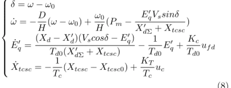
The dynamics of this plant system (Wang et al., 2002) can be expressed by means of the following nonlinear differential equations: ˙δ = ω − ω0 ˙ω = −D H(ω − ω0) + ω0 H(Pm− E′ qVssinδ X′ dΣ+ Xtcsc ) ˙ E′ q = (Xd− Xd′)(Vscosδ − Eq′) Td0(XdΣ′ + Xtcsc) − 1 Td0 E′ q+ Kc Td0 uf d ˙ Xtcsc= − 1 Tc (Xtcsc− Xtcsc0) + KT Tc uc (8) In this model, the symbols represent: δ and ω are the angle and speed of the generator rotor, respectively; H is the inertia constant; Pm is the mechanical power on the generator shaft; D is the damping coefficient; E′
q and Vs are the inner generator voltage and infinite bus voltage, respectively; Tc is the time constant of TCSC; Td0is the direct axis transient open circuit time constant, respectively; Vtis the terminal voltage; XdΣ′ = XT+ Xd′+
1
2(X1+ X2), XdΣ = XT + Xd + 1
2(X1+ X2); XT is the reactance of the transformer; Xd and Xd′ are the direct axis reactance and transient reactance, respectively, of the generator; X1and X2are the line reactance whereas Xtcsc is the reactance of TCSC device; Xtcsc0is the initial stable value of ; Kc is the gain of the excitation amplifier; uf d is the excitation voltage; KT is the gain of TCSC regulator and uc is the reactance modulated input of TCSC. It should be noted that, generally speaking, the damping coefficient D can not be measured accurately. Hence D is an unknown and/or uncertain constant parameter. There-fore θ = −D
H is also an unknown and/or uncertain constant parameter, and this fat causes difficulties that should be overcome.
3.2 Controller Design
Now we are ready for designing the robust controller via coordinated passivation techniques when damping coeffi-cient is measured inaccurately so as to achieve asymptotic stability of rotor angle and speed in the power system simultaneously.
Let (δ0, ω0, Eq0′ , Xtcsc0) represents an operating point of the power system. Define the system state variables as x1= δ − δ0, x2= ω − ω0, x3= Eq′ − E
′
q0 and x4= Xtcsc− Xtcsc0. Then the inputs are u1 = uc and u2 = uf d, and the output is y = x4= Xtcsc− Xtcsc0. The system (8) is thus transformed into the following form
˙x = x2 ω0 HPm+ θx2− ω0(x3+ Eq0′ )Vssin(x1+ δ0) H(X′ dΣ+ y + Xtcsc0) (Xd− Xd′)(Vscos(x1+ δ0) − x3− Eq0′ ) Td0(XdΣ′ + y + Xtcsc0) − x3+ Eq0′ Td0 + 0 0 Kc Td0 u2 (9) ˙y = − 1 Tc y +KT Tc u1 (10)
For the system (9) and (10), we choose the input-output pair (u1, y) for which the system has relative degree one. Then the design is divided into two parts. First, we stabilize the zero dynamics with the input u2. Then, passivation method is used to design the input u1 so as to make the whole system asymptotically stable in closed loop.
(1) Control the zero dynamics subsystem by means of the adaptive back-stepping technique
Following the ideas of the coordinated passivation method, when the control for TCSC is not considered, the excita-tion voltage is designed.
From (9), the zero dynamics subsystem with the uncertain damping coefficient can be written as follows:
˙x1= x2 ˙x2= ω0 HPm+ θx2− ω0(x3+ Eq0′ )Vssin(x1+ δ0) H(X′ dΣ+ Xtcsc0) ˙x3= (Xd− Xd′)(Vscos(x1+ δ0) − x3− E′q0) Td0(XdΣ′ + Xtcsc0) −x3+ E ′ q0 Td0 + Kc Td0u2 (11) In the following procedure, we will design the control law by using the adaptive back-stepping method.
Step1 : For the first subsystem of system (11), x2 is assumed to be the virtual control variable. Then we choose the virtual control of x2 as x∗2= −c1x1, where c1> 0 is a design parameter. Define error variable z2= x2− x∗2 and z1= x1. Then
˙z1= z2− c1x1. (12)
For the system (12) we choose Lyapunov function V1=
1 2z
2
1. (13)
The time derivative of V1 along the system trajectory is ˙
V1= z1(z2−c1z1) = z1z2−c1z12. It is apparent that ˙V1≤ 0 when z2= 0.
Step2 : Augment Lyapunov function of Step 1 as V2= V1+
1 2z
2
2, (14)
and notice that ˙z2 = ˙x2 − ˙x∗2 = ωH0Pm + θx2 − ω0(x3+Eq0′ )Vs
H(X′
dΣ+Xtcsc0)
sin(x1+ δ0) + c1x2. Thus the time derivative of V2along the system trajectory is
˙ V2= ˙V1+ z2˙z2= −c1z12+ z2[z1+ ω0 HPm+ θx2 − ω0(x3+ E ′ q0)Vs H(X′ dΣ+ Xtcsc0) sin(x1+ δ0) + c1x2]. (15) For the (15), x3 is assumed to be the virtual control variable. Define error variable z3= x3−x∗3. Then we choose the virtual control of x3as x∗3=
H(X′ dΣ+Xtcsc0) ω0Vssin(x1+δ0)[z1+ ω0 HPm+ ˆ
θx2+ c1x2+ c2z2] − E′q0, where ˆθ stands for the estimate of θ, and c2> 0 is another design constant. Next, we define the estimation error ˜θ = θ − ˆθ, and then it follows:
˙
V2= −c1z12− c2z22+ z2θx˜ 2− z2ω0Vssin(x1+ δ0) H(X′
dΣ+ Xtcsc0) z3. Step3 : Augment Lyapunov function of Step 2, and thus Lyapunov function for zero dynamics subsystem is
V3(z1, z2, z3, ˜θ) = V2+1 2z 2 3+ 1 2γθ˜ 2, (16)
where γ is the adaptive gain coefficient. Note that˙˜θ = −˙ˆθ, and ˙z3= ˙x3− ˙x∗3. Thus the time derivative of V3along the system trajectory is ˙ V3= ˙V2+ z3˙z3+1 γθ˜˙˜θ = −c1z 2 1− c2z22+ z2θx˜ 2−1 γθ˜˙ˆθ +z3{−z2 ω0Vssin(x1+ δ0) H(X′ dΣ+ Xtcsc0) +(Xd− X ′ d)Vscos(x1+ δ0) Td0(XdΣ′ + Xtcsc0) −(Xd− X ′ d)(x3+ Eq0′ ) Td0(XdΣ′ + Xtcsc0) +H(X ′ dΣ+ Xtcsc0) ω0Vssin(x1+ δ0) [x2+ c1c2x2 +(ˆθ + c1+ c2)( ω0 HPm+ θx2+ c1x2) +˙ˆθx2− (x1+ ω0 HPm +c1x2+ c2z2+ ˆθx2)ctg(x1+ δ0)] + Kc Td0 u2− (x3+ E ′ q0)}. Choose the feedback control law
u2= Td0 Kc {z2 ω0Vssin(x1+ δ0) H(X′ dΣ+ Xtcsc0) −(Xd− X ′ d)Vscos(x1+ δ0) Td0(XdΣ′ + Xtcsc0) +(Xd− X ′ d)(x3+ E ′ q0) Td0(XdΣ′ + Xtcsc0) −H(X ′ dΣ+ Xtcsc0) ω0Vssin(x1+ δ0) [c1c2x2+ x2 +(ˆθ + c1+ c2)(ω0 HPm+ ˆθx2+ c1x2) +˙ˆθx2− (x1+ c1x2 +ω0 HPm+ c2z2+ ˆθx2)ctg(x1+ δ0)] + (x3+ E ′ q0) − c3z3}, (17) where c3> 0 is another design constant.
If the parameter update law is selected as ˙ˆθ = γ[z2+ z3
H(X′
dΣ+ Xtcsc0)(ˆθ + c1+ c2) ω0Vssin(x1+ δ0)
then ˙V3 = 3 P i=1 zi˙zi = 3 P i=1 −ciz2i < −α(kzk), where ci(i = 1, 2, 3) are positive constants, α is a class-K function. Therefore, under the feedback control law (17), the zero dynamics closed-loop system
˙z1= z2− c1z1 ˙z2= −c2z2− z1+ ˜θx2− ω0Vssin(x1+ δ0) H(X′ dΣ+ Xtcsc0) z3 ˙z3= −c3z3+ z2ω0Vssin(x1+ δ0) H(X′ dΣ+ Xtcsc0) +H(X ′ dΣ+ Xtcsc0)(ˆθ + c1+ c2) ω0Vssin(x1+ δ0) ˜ θx2 ˙ˆθ = γ[z2+ z3 H(X′ dΣ+ Xtcsc0)(ˆθ + c1+ c2) ω0Vssin(x1+ δ0) ]x2 (18)
is asymptotically stable. In fact, ˙V3 < −α(kzk) ≤ 0, implies V3(t) ≤ V3(0), i.e. z1, z2, z3are all bounded. Define Ω = − ˙V3, then R
t
0Ω(τ )dτ = V3(0) − V3(t). Since V3(0) is bounded, and V3(t) is non-increasingly bounded, then
lim t→∞
Rt
0Ω(τ )dτ < ∞. In addition, since ˙Ω is bounded, lim
t→∞Ω = 0 holds due to Barbalat’s lemma. So z1 → 0, z2 → 0, and z3 → 0 as t → ∞. From the definition of x1, x2, x3, x∗2, x
∗
3, it is apparent that the system state variables x1, x2, x3also converge to zero.
It is therefore that, when the reactance modulated input uc= 0, u2 can stabilize the system (9) with v = 0. (2) The design by using coordination passivation method Now we proceed to the next design step, to the feedback passivation. That is, we proceed to design uc to stabilize the whole system (9) and (10). Let W = V3. We select the storage function V = W (z) + 1
2y
2, and the control law
u1= uc= Tc KT {−z2 ω0(x3+ Eq0′ )Vssin(x1+ δ0) H(X′ dΣ+ Xtcsc0)(X ′ dΣ+ Xtcsc0+ y) +z3 (Xd− Xd′)[x3+ Eq0′ + Vscos(x1+ δ0)] Td0(XdΣ′ + Xtcsc0)(XdΣ′ + Xtcsc0+ y) + v}. (19) Then the time derivative of V along the system trajectory is ˙ V = ˙W + y ˙y = ∂W (z) ∂z ˙z|y=0− 1 Tc y2+ vy ≤ −1 Tc y2+ vy. From Definition 2.1, we know the system output is strictly passive. If we choose v = −βy(β > 0), then ˙V ≤ 0 and y(t) → 0 as t → ∞.
We now study the invariant set with y ≡ 0. From the positive limit set and LaSalle’s theorem, it follows x1 → 0, x2 → 0 and similarly x3 → 0 as well. It is therefore that the system is zero-state observable. Hence, under the proposed control design, the SMIB system with generator excitation and TCSC is asymptotically stable.
Remark 1. If sin(x1+δ0) = 0, that is if δ = kπ, k = 0, 1, 2, ·· ·, synchronism of the power system will be lost and there is no longer normal operation. Fortunately, under the normal operating conditions in the system 0 < δ < π holds, and
therefore the condition sin(x1+δ0) 6= 0 can be guaranteed in (17).
4. UNITS NUMERIC AND SIMULATION RESULTS Simulation of the overall system has been carried out by using Matlab software on the grounds of the above control design results. The SMIB case system exam-ple solved has the following parameters (Wang et al., 2002): E′
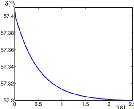
q0 = 1.0149, Vs = 1, XT = 0.127, X1 = X2 = 0.2426, Xd = 1.863, Xd′ = 0.257, δ0 = 57.3◦, ω0 = 314.159rad/s, Xtcsc0 = 0, Td0 = 6.9, Tc = 0.06, c1 = 2, c2 = 2, c3 = 2, γ = 2, β = 2, H = 4. A set of the responses are depicted in Figure 2, Figure 3, and Figure 4; corresponding to arbitrary chosen nonzero initial states.
0 0.5 1 1.5 2 2.5 57.3 57.32 57.34 57.36 57.38 57.4 t(s) δ(°)
Fig. 2. Transient response of the rotor angle
0 0.5 1 1.5 2 2.5 313.7 313.8 313.9 314 314.1 314.2 t(s) ω(rad/s)
Fig. 3. Transient response of the speed
0 0.5 1 1.5 2 2.5 −0.15 −0.1 −0.05 0 0.05 0.1 0.15 0.2 t(s) X tcsc(pu)
Fig. 4. Transient response of the reactance controlled by TCSC
Figure 2, Figure 3, and Figure 4 show that under robust coordinated passivation controller, the speed of response is indeed considerably fast, and the system reaches the stable state rather rapidly. Through repeated simulation
experimentation procedure we noticed that the smaller value of γ is, the better effect of parameter adaptation is. However, since too small γ causes the controller become excessively sensitive for slight disturbances, by comparison analysis of simulation responses and from the expression of the control law, we established that the controller gain increase further to non-acceptable values. Even it might happen that the controller can not be implemented. Therefore, for the parameter γ , a moderate value should be carefully selected.
5. CONCLUSIONS
A novel design for the generator excitation and TCSC robust coordinated passivation controller when damping coefficients are unknown has been derived. First, the exci-tation voltage input is obtained by adaptive back-stepping and Lyapunov methods to achieve stability of rotor angle, speed and voltage. Parameter updating law are obtained simultaneously. And then the reactance modulated input is obtained by using passivity approach to achieve sta-bility of reactance of TCSC, such that the whole system is in the effective operating state. Computer simulations verified the effectiveness of the proposed nonlinear control design. Further studies will be devoted to the extension of this approach to robust control design for the case with simultaneous presence of external disturbances.
At the control design stage, the coordinated passivation method is exploited to divide the system into two parts and curry out the design respectively. For the first part, the design complexity is remarkably reduced. The design for the other part yielded an improved design effect for the whole system. Since the controller design is based on the nonlinear model of the plant dynamics without linearizing it, nonlinear features of the plant model are exploited to the full yielding a robust nonlinear controller. And robustness for system parameter variety is considerably stronger because the damping coefficient is considered within the setting of internal parameter uncertainty.
REFERENCES
Abdel-Magid, Y. L. and M. A. Abido (2004). Robust coordinated design of excitation and TCSC-based stabi-lizers using genetic algorithms. Electric Power Systems Research, 69(2-3), 129-141.
Abido, M. A. (2000). Pole placement technique for PSS and TCSC-based stabilizer design using simulated an-nealing. Int. J. of Electric Power Systems, 22(8), 543-554.
Bazanellan, A. S. and C. L. Conceic (2004). Transient stability improvement through excitation control. Intl. J. of Robust & Nonlinear Control, vol.14, 891-910. Chaudhuri, B and B.C. Pal (2004). Robust damping
of multiple swing modes employing global stabilizing signals with a TCSC. IEEE Trans. on Power Systems, 19(1), 499-506.
Chen, H., H.-B. Ji, B. Wang and H.-S. Xi (2006). Co-ordinated passivation techniques for the dual-excited and steam-valving control of synchronous generators. IEE Proceedings J. on Control Theory & Applications, 153(1), 69-73.
Dimirovski, G. M., Y.-W. Jing, W.-L. Li and X.-P. Liu (2006). Adaptive back-stepping design of TCSC robust
nonlinear control for power systems. Intelligent Automa-tion & Soft Computing, 12(1), 75-87.
Farsangi, M. M., Y. H. Song and K. Y. Lee (2004). Choice of FACTS device control inputs for damping inter-area oscillations. IEEE Trans. on Power Systems, 19(2), 1135-1143.
Isidori, A. (1995). Nonlinear Control Systems (3rd Ed). Berlin, DE: Springer-Verlag.
Khalil, H. K. (2002). Nonlinear Systems (3rd Ed). Upper Saddle River, NJ: Prentice-Hall.
Kokotovi´c, P. V. and M. Arcak (2001). Constructive nonlinear control: A historical perspective. Automatica, 37(5), 637-662.
Kuiava, R., R. V. de Oliveira, R. A. Ramos and N. G. Bretas (2006). Simultaneous coordinated design of PSS and TCSC damping controller for power systems. The 2006 General Meeting of the IEEE Power Engineering Society, 1-8.
Lan, H., D. G. Xu, S. Liu, L. H. Yang, S. K. Qu, et al. (2006). Study on Dissipative Theory in Coordinated Control for TCSC and Generator Excitation. Journal of System Simulation, 18(8), 2230-2234.
Larsen, M., M. Jankovi´c and P. V. Kokotovi´c (2003). Coordinated passivation designs. Automatica, 39(2), 335-341.
Lei, X., X. Li and D. Povh (2001). A nonlinear control for coordinating TCSC and generator excitation to enhance the transient stability of long transmission systems. Electric Power Systems Research, 59(2), 103-109. Li, X. Y. (2006). Nonlinear controller design of thyristor
controlled series compensation for damping inter-area power oscillation. Electric Power Systems Research, 76(12), 1040-1046.
Mei, S. W., T.L. Shen and K.Z. Liu (2003). Modern Ro-bust Control Theory and Application, Beijing: Tsinghua University Press.
Paul, M. O. and E. P. Gerardo (2004). Output feedback excitation control of synchronous generators. Intl. J. of Robust & Nonlinear Control, vol. 14, 879-890.
Sae-Kok, W., A. Yokoyama, S.C. Verma and S. Ogawa (2006). Excitation Control System Design of Rotary Type Frequency Converter for Performance Improve-ment of Power System Dynamics. IEEE Trans. on Energy Conversion, 21(1), 210-220.
Wang, Y., L. Xie, D. J. Hill and R. H. (1992). Middleton Robust nonlinear controller design for transient stability enhancement of power systems. in Proceeding of the 31st IEEE Conference on Decision and Control, Tucson, Arizona, USA, 1117-1122.
Wang, Y., D. J. Hill, L. Gao and R. H. (1993). Middleton Transient stability enhancement and voltage regulation of power systems. IEEE Trans. on Power Systems, 8(2), 620-627.
Wang, Y., Y. L. Tan and G. Guo (2002). Robust nonlinear co-ordinated excitation and TCSC control for power sys-tems. IEE Proceedings J. on Generation, Transmission & Distribution, 149(3), 367-372.