Liquid Level Process Control with Fuzzy Logic Based Embedded System
1
Barış Çelik,
2Sibel Birtane,
2Emrah Dikbıyık,
1Hasan Erdal
1Marmara University, Faculty of Technology Electrical-Electronics Engineering, Istanbul, Turkey
[email protected], [email protected]
2
Istanbul Arel University, Vocational High School, Istanbul, Turkey [email protected], [email protected]
Abstract
In this study, the design of embedded Sugeno fuzzy logic based controller for controlling non-linear liquid level process is realized. First, the system was activated on Matlab-Simulink platform and uploaded to Arduino Mega. With this study, activation of modern control methods on embedded systems is simplistically proven. When the control system operation was checked out, it has been observed that it was pretty successful.
1. Introduction
There are a lot of fuzzy logic based controller implementations in the industry such as control of tank level, greenhouse cultivation to prepare the most suitable environment for living of plants, livestock farming to keep the eggs at the suitable temperature by arranging internal temperatures of incubators, food industry to obtain top quality products by keeping the boilers at the wanted temperature, control of deteriorative effects of environmental factors in ornamental pools, and air conditioners.
One of the aims of the fuzzy logic is to make computers think as people do. Usage of fuzzy logic algorithms makes it possible to understand human thoughts such hot, cold, big, small etc. with ambiguous concepts and answer for machines. At the same time, it may provide a relatively simpler approach to reach definite results from indefinite information. Fuzzy logic may have some benefits for nearly each implementation including embedded control implementations. The usage of fuzzy logic in the embedded systems may increase performance, productivity, ease of improving implementation and decrease the cost of market and duration of project development [1].
To constitute fuzzy logic algorithms, human experience is needed at the stage of imitating expertness or thoughts. Besides; training determination of a fuzzy logic is a compelling task [2]. Great numbers of implementations including embedded implementations combine usage of fuzzy logic and artificial neural networks. Systems developed with improved fuzzy-neural network topology by taking advantage of this combination of human decision-making process may imitate:
x Indefinite and uncertain information processing.
x Learning expert experience information.
x Teaching and organizing itself [2].
Many implementations on this field are available in the literature. Although there are hardware differences, it seems that
fuzzy logic is used as a computer based controller. In this study, S. Srivastava et al. improved a new laboratory environment in which embedded fuzzy logic implementations could be performed. Fuzzy logic implementations which are made on Matlab were turned into C code by using MCC and operated by uploading to the microprocessor. During the observations, it seemed that students improved their engineering talents by performing implementation and reinforced information that they previously learned [3]. S. Krivic et al. used fuzzy logic in control of water level. Controller with fuzzy logic was designed by using the mathematical model of tank system on Matlab platform. On the other hand, Arduino Uno was used to transfer sensor information to the computer. Evaluations within the framework of obtained results showed that fuzzy logic system yielded better results than PID system did [4]. In the study by Min Huang et al., microprocessor implementation of fuzzy logic control which was performed on an unmanned ground vehicle (UGV) was realized. The result of fuzzy logic was uploaded to the processor as look-up to be able to use fuzzy logic real time. This also made operation time shorter and easier [5]. Ramadan Ebrahim Abd El-Hamid Mohamed and et al. made FPGA based fuzzy logic and PI controller design for engine control. The aim of presented design is to prevent the angular velocity of the engine from being affected by the load change and keep it at the desired velocity. Performed experimental studies showed that designed fuzzy logic system had better watching performance [6]. In this study A.R. Patil et al. made accumulator charge implementation with fuzzy logic based buck DC-DC converter. The implementation was realized by using PIC microcontroller. The system uses solar panel as a power supply. The voltage change of the solar panel is minimized by buck converter [7]. When fuzzy logic implementations made with embedded systems are analyzed, it seems that in general microprocessors are programmed with C language and FPGAs are programmed with either Verilog or VHDL languages. This also makes it harder to design modern control methods on embedded systems and restricts the use of embedded systems because; a little change after designing is required in order to change the whole software. Besides, it seems that microprocessors were used in communication between the computer and the system in some studies in the literature.
In this study fuzzy logic based liquid level control was realized on an embedded system. Embedded systems are not commonly used in modern control methods because these systems require expertness and take the long time. However, Matlab has recently given programming support to many embedded systems. One of these systems is Arduino Mega. In this study, embedded system, which one of the modern control
methods, is operated by simply designing on Arduino Mega thanks to this feature of Matlab. When the designed system is tested, it seemed that it worked successfully. It also shows that modern control methods on embedded systems could be used not only for academical but also industrial for industrial purposes.
This paper continues with the introduction of liquid level system in the second section, design of fuzzy control system in the third section, implementation results in the fourth section and finally conclusions and recommendations in the fifth section.
2. General Structure Of Gunt RT 512 System Gunt RT 512 liquid level unit is a system which controls the level of liquid in a transparent tube and similar to the systems used in industry. The aim of the system is to reach the liquid level in the tube to the reference value. It has pneumatic energy input, proportional valve with 4-20 mA current control input, liquid tank, a pomp driven by a single phase induction motor, return valve (disturbance valve), pressure sensor, pressure/current transducer, 0-62 cm scale level transparent tube, and UDC 5000 digital controller. As shown in Figure 1, its structure consists of eight components as follows:
1. Transparent liquid level tube
2. Pressure sensor
3. Scaled spherical return valve(disturbance valve)
4. Pumping storage tank
5. Pneumatic control valve
6. Constant line recorder
7. Main pulpit
8. Controller
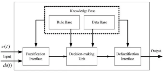
Fig. 1. General Structure of the Gunt RT 512 System 3. Design Of Fuzzy Control System As shown in Figure 2, fuzzy logic firstly blurs the input variables(fuzzification process). Then, after outlets are found by the rule mechanisms, it is turned into numerical data via clarification.
Fig. 2. Fuzzy Logic Working Priciple
When the system of liquid level control is designed with fuzzy logic algorithm, questioning blocks are created based on errors, error changes (derivatives of error) and references values and it is found out in which interval error and error change is in. The reference input is used to multiply output in the Sugeno fuzzy logic system with a coefficient which will directly influence it. As liquid level increases, more water must be put into the tank in order to keep the system at the desired reference. More voltage must be given to electro-pneumatic valve in order to give more water to the tank. Therefore, the reference input is divided by 60 and added to the fuzzy logic output.
Fig. 3. Fuzzy Logic Flow Diagram in Matlab 3.1. System Inputs
Six different membership function were used for error input factor. Used linguistic tags are defined as negative high (NH), negative average (NA), negative low (NL), positive high (PH), positive average (PA) and positive low (PL). Error change was defined with three different membership function, which are change negative (CN), change null (CN) and change positive (CP). As shown in Figure 4 and 5, graphical display of membership functions for the error and error change are shown. Membership functions are defined in (-25, 25) space.
Fig. 5. Error Change Variable Membership Function 3.2. System Outputs
Level control is made by changing the space of control signal valve which is system output. The rule base is evaluated based on error and error change amounts, control valve with the electronic actuator is arranged as a certain percentage of the maximum valve in order to control liquid level.
3.3. Rule Bases
A total of 21 rules were constituted for the control of the system. Each of the rules has an impact on output signal at the rate of own control act.
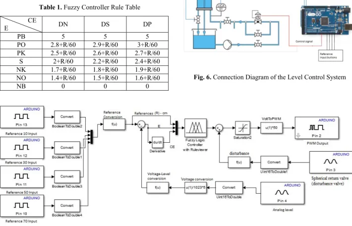
Table 1. Fuzzy Controller Rule Table CE E DN DS DP PB 5 5 5 PO 2.8+R/60 2.9+R/60 3+R/60 PK 2.5+R/60 2.6+R/60 2.7+R/60 S 2+R/60 2.2+R/60 2.4+R/60 NK 1.7+R/60 1.8+R/60 1.9+R/60 NO 1.4+R/60 1.5+R/60 1.6+R/60 NB 0 0 0
3.4. Design of Embedded Controller
Arduino Mega is a microprocessor card with an ATmega2560 processor. It has 54 digital input/output pins and 14 of them could be used as PWM output. Besides it has 16 analog input pins. It operates with its 16 MHz crystal oscillator. To program Arduino Mega, the software called "Arduino", which is provided by the producer, is used. Because Arduino is an open source, there are a lot of examples made with this system on the Internet [8]. However, as part of this study, Arduino Mega was programmed with Matlab Simulink. As shown in Figure 7 of Simulink block diagram, 4 buttons were connected to Arduino Mega for the reference input. These buttons respectively 10, 30, 50 and 70 cm are used to define liquid level references to the system. A potentiometer could be connected to an analog input instead of these buttons; however, reference to observe the working of the system specific reference values need to be defined. Therefore, reference information is preferred to define by the help of the buttons. In Figure 6, connection diagram of the control system is shown.
Fig. 6. Connection Diagram of the Level Control System
Fig. 7. Block Diagram of Level Control System in Simulink In Section 2, it was stated that 3 input information was
needed to control the system with the fuzzy controller: the values of the error, error change and defined references. After references information is defined via the button, error information is obtained by taking off the level information which comes from this information and the information which comes
from the level sensor connected to the analog input. Three inputs which are needed by the logic block are obtained by taking the derivative of this error information. Fuzzy logic tries to cancel out the error in accordance with obtained information by producing the most suitable output. Spherical return valve (disturbance valve) of the tank is not stable to a stable openness.
Thus, the control system also needs to know about this openness information. Because of this, this information was defined to the analog input of Arduino. Openness information of the disturbance valve, unlike reference information, is not defined to the fuzzy logic block because the effect of the cock to the system is not linear. Due to the fact that a quadratic polynomial cannot be added to Sugeno fuzzy logic system, the effect of the disturbance valve to the system were tested for some values and added to the fuzzy logic output via the spline fit method. Finally, output information was transferred to PWM output of Arduino and electro-pneumatic valve which gave water to the tank was checked.
4. Implementation Results
The control system was first installed on Matlab/Simulink and was operated in External mode in order to test the system at different levels and different degrees of disturbance valve as shown in Figure 8-11. Afterwards, when the system was observed to performing at a suitable level, reference information and disturbance valve inputs of the system were changed in accordance with data flow from Arduino, and control system was embedded in Arduino Mega. Prior to uploading process, the hardware to be uploaded was selected in "Options" section of "Run on Target Hardware". Then, "Deploy to Hardware" in "Tools" menu was selected and the control system in Simulink was uploaded to Arduino Mega.
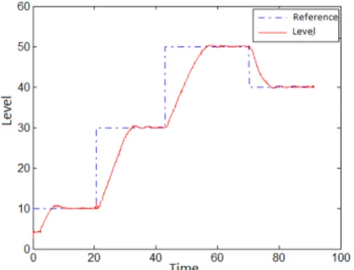
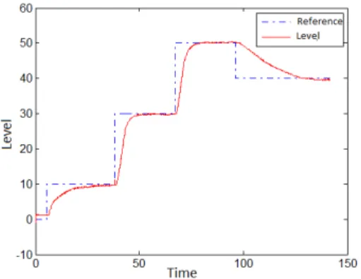
When system response at different disturbance valve degrees are analyzed as follows, the control system is very successful in both Simulink, as shown in Figure 8-11, and Arduino, as shown in Figure 12-15.
Fig. 8. Level graph of disturbance valve at 10 degrees
Fig. 9. Level graph of disturbance valve at 30 degrees
Fig. 10. Level graph of disturbance valve at 50 degrees
Fig. 11. Level graph of disturbance valve at 70 degrees
Fig. 12. Level graph of Arduino Controlled System when disturbance valve is at 10 degrees
Fig. 13. Level graph of Arduino Controlled System when disturbance valve is at 30 degrees
Fig. 14. Level graph of Arduino Controlled System when
disturbance valve is at 50 degrees
Fig. 15. Level graph of Arduino Controlled System when disturbance valve is at 70 degrees
5. Conclusion and Recommendations
Embedded systems have been widely used in recent years.
This is because embedded systems are inexpensive and requires low energy. However, these systems are not preferred in modern control applications due to the difficult adaptation and programming. Because any changes in the system to be controlled may change all software programs, it is not widely used in modern control applications.
This study was carried out by uploading fuzzy logic, which is one of the modern control methods, to the Arduino Mega via Matlab/Simulink add-on. In this context, the system was first installed on Simulink for non-linear liquid level control and was later uploaded to Arduino, which enabled to program Arduino Mega in an easier way. Graphs suggest that control system operates quite successfully.
References
[1] Alçı, M., Karatepe, E. (2002), " Fuzzy Logic and Matlab Implementations."
[2] Ibrahim, A. (2003). “Fuzzy logic for embedded systems applications.” Newnes.
[3] Srivastava, Smriti, et al. "A laboratory testbed for embedded fuzzy control." Education, IEEE Transactions on 54.1 (2011): 14-23.
[4] Krivic, Senka, et al. "Design and implementation of fuzzy controller on embedded computer for water level control." MIPRO, 2012 Proceedings of the 35th International Convention. IEEE, 2012.
[5] Huang, Min, and Dagui Huang. "Embedded fuzzy logic control of AGV in path tracking." Mechatronics and Automation (ICMA), 2010 International Conference on. IEEE, 2010.
[6] Ramadan, Ebrahim Abd El-Hamid Mohamed, et al. "Embedded system based on a real time fuzzy motor speed controller." Ain Shams Engineering Journal 5.2 (2014): 399-409.
[7] Patil, A. R., et al. "Embedded Fuzzy Module for Battery Charger Control." International Journal of Advanced Research in Electrical, Electronics and Instrumentation Engineering 2.8 (2013): 4072-4078.