Selçuk J. Appl. Math. Selçuk Journal of Vol. 13. No. 1. pp. 11-21, 2012 Applied Mathematics
Flow of Micropolar Fluid through a Porous Tube of Varying Cross-Section in the Presence of Magnetic Field
D. Srinivasacharya, Mekonnen Shiferaw
Department of Mathematics, National Institute of Technology, Warangal-506 004, India
e-mail: dsc@ nitw.ac.in, dsrinivasacharya@ yaho o.com
Department of Mathematics, Arba Minch University, Ethiopia e-mail: m ekk_ aya@ yaho o.com
Received Date: November 8, 2010 Accepted Date: May 17, 2012
Abstract. The steady flow of incompressible and electrically conducting mi-cropolar fluid through a tube with permeable wall of slowly varying cross-section is studied. The fluid motion is subjected to an external uniform magnetic field directed transverse to the flow direction. Assuming small aspect ratio and ne-glecting the inertia terms, a closed form solutions are obtained for velocity and microrotation components. The profiles of velocity and microrotation compo-nents presented for different micropolar fluid parameters, magnetic parameter and wall absorption parameter. The variation of wall skin friction is presented graphically for different flow geometries.
Key words: Magnetohydrodynamics; Micropolar fluid; Permeable wall; Vary-ing cross-section.
2000 Mathematics Subject Classification: 76A05, 76W05. Nomenclature
a (z) Arbitrary wall surface function a0 Tube characteristic radius
B0 Magnetic induction
Ha Hartmann number H (z) Arbitrary flux funtion j The micro inertia parameter L Tube characteristic length m Micropolar parameter
N Coupling number (0 ≤ N < 1) p Fluid pressure
(r, θ, z) Cylindrical polar coordinate system
Re The entrance flow Reynolds number
S The funtion describing the tube varying wall geometry u (r, z) , w (r, z) Velocity components
U The entrance flow characteristic velocity (i.e at z = 0)
ρ Fluid density
E Aspect Ratio
μ, κ, γ Material constants (viscosity coefficients) (Eringen, 1996) σ Electric conductivity of the fluid
φ1 The non-dimensional asymptotic flux
φ2 The wall absorption parameter
ψ (r, z) Stream function
υ (r, z) Microrotation component 1. Introduction
The increasing number of technical applications using magnetohydrodynamic (MHD) effects has made it desirable to extend many of the available hydrody-namic solutions to include the effects of magnetic fields for those cases when the fluid is electrically conducting. After the pioneering works of Hartmann and Lazarus [1] in relation to the effect of magnetic fields on the laminar flow of viscous fluids between parallel plates, several researchers [2, 3, 4] have stud-ied similar effects in many other flow geometries including converging/diverging channels. The study of MHD flow through converging or diverging channels or tubes has applications in mathematical modeling of several industrial and biological systems such as in the field of industrial metal casting i.e. the control of molten metal flows, in the motion of liquid metals or alloys in the cooling systems of advanced nuclear reactors and also in physiological flow problems. In recent times, many medical diagnostic devices especially those used in di-agnosing cardiovascular diseases make use of the interaction of magnetic fields with tissue fluids. It is also applicable in the development of magnetic device for cell separation, targeted transport of drugs using magnetic particles as drug carriers, magnetic wound or cancer tumor treatment causing magnetic hyper-thermia, reduction of bleeding during surgeries or provocation of occlusion of the feeding vessels of cancer tumors and development of magnetic tracers [5] . The flow of fluids through tubes of varying cross-section with permeable wall has several applications such as blood flow in arteries, acoustics, lubrication and internal combustion engines as well as various industrial processes where fluid transport on filtrations are very essential e.g. petroleum refinery industries. Several authors, Manton [6], Ramachandra Rao and Rathna Devanathan [7] , Schneck and Ostrch [8], Srinivasacharya et al [9] and Makinde [10] mentioned but few, have studied the laminar flow of an incompressible viscous fluid in a converging or diverging channels or tubes.
The study of non-Newtonian fluid flows has gained much attention by the re-searchers because of their applications in biology, physiology, technology and
industry. In addition, the effects of magnetic field on the non-Newtonian fluid also have great importance in engineering applications. The theory of micropo-lar fluids initiated by Eringen [11] exhibits some microscopic effects arising from the local structure and micro motion of the fluid elements. Further, they can sustain couple stresses and include classical Newtonian fluid as a special case. The model of micropolar fluid represents fluids consisting of rigid randomly oriented (or spherical) particles suspended in a viscous medium where the de-formation of the particles is ignored. The fluids containing certain additives, some polymeric fluids and animal blood are examples of micro polar fluids. The mathematical theory of equations of micropolar fluids and applications of these fluids in the theory of lubrication and in the theory of porous media is presented by Lukaszewicz [12].
In the present study, the flow of an incompressible micropolar fluid through a tube of varying cross-section is investigated under the influence of transverse magnetic field. The governing equations are solved analytically by neglecting the inertia terms. The effects of Hartmann number, coupling number and the absorption parameters on velocity and microrotation are reported. The vari-ation of wall skin friction for various values of wall absorption parameter is studied.
2. Mathematical formulation
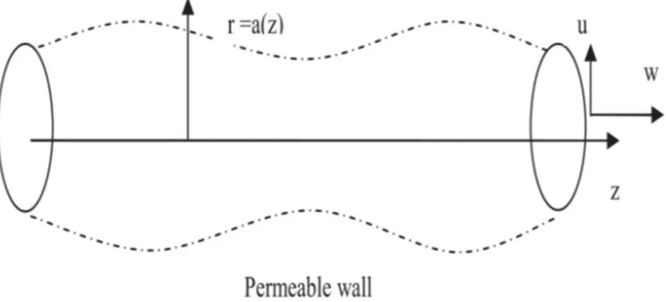
Consider a steady incompressible electrically conducting micropolar fluid flow in a tube of slowly varying cross-section. Choose the cylindrical polar coordinate (r, θ, z) system such that r = 0 is the axis of the symmetry. A uniform magnetic field B0 is applied to the fluid normal to the flow direction. Assume that the
magnetic Reynolds number (the characteristic ratio of the induced to applied magnetic field strengths) is very small so that the induced magnetic field can be neglected. The geometry of the wall surface is assumed as an arbitrary function of z (i.e. r = a(z)) and the wall is permeable.
Since the flow is axisymmetric, all the flow variables are independent of θ. Hence, for this flow the velocity vector is given by (u(r, z), 0, w(r, z)) and microrotation vector is (0, υ(r, z), 0). Within the framework of these assumptions, the equa-tions that comprise the MHD flow in the absence of both body force and body couple are (1) ∂u ∂r + u r + ∂u ∂z = 0 (2) ρ[u∂u ∂r+ w ∂u ∂z] = − ∂p ∂r− κ ∂υ ∂z− (μ + κ)( ∂2u ∂r2 + ∂2u ∂z2 + 1 r ∂u ∂r2− u r2) − σB 2 0u (3) ρ[u∂w ∂r + w ∂w ∂z] = − ∂p ∂z−κ( υ r+ ∂υ ∂r) + (μ + κ)( ∂2w ∂r2 + ∂2w ∂z2 + 1 r ∂w ∂r) −σB 2 0w (4) ρj[u∂υ ∂r + w ∂υ ∂z] = −2κυ − κ( ∂w ∂r − ∂u ∂z) + γ( ∂2υ ∂r2 + ∂2υ ∂z2 + 1 r ∂υ ∂r2 − υ r2)
where p is the fluid pressure, ρ is the density of the fluid, j is the micro inertia parameter, σ is the electric conductivity of the fluid and B0 is the magnetic
induction. μ, κ, and γ are the material constants (viscosity coefficients) which satisfy the following inequalities.
(5) κ ≥ 0, 2μ + κ ≥ 0, 3α + β + γ ≥ 0, γ ≥ |β|
In the limit κ → 0 the equations (2) and (3) are uncoupled with (4) and they reduce to the classical Navier-Stokes equations. Hence the flow of viscous fluid can be obtained as a special case from the present analysis.
The appropriate boundary conditions are the regularity of the solution along z - axis, no slip condition for the tangential velocity at the wall and hyperstick condition for the microrotation at the wall. The hyperstick condition can be expressed by the statement that there is no slip at the boundary and that a fluid particle is inflexibly attached to it so that the microrotational velocity of the particle on the boundary equals to the angular velocity of the boundary.
(6) ∂w
∂r = 0, u = 0, υ = 0, at r = 0
(7) w + (da
dz)u = 0, υ = 0, at r = a(z) The flow rate across any cross-section of the tube is
(8) a(z) Z 0 2π Z 0 rwdθdr = 2πU a20H(z/L)
where U is the entrance flow characteristic velocity (i.e at z = 0), H(z) is the arbitrary flux function of axial distance defined such that H(0) = 1 corresponds to the case of an impermeable wall, a0 is the tube characteristic radius and L
is tube characteristic length.
Assume that the function a(z) depends upon a small parameter ε such that a(z) = a0S(εz/a0), (0 < ε = a0/L << 1)
where S is the function describing the tube varying wall geometry. In the limit ε → 0 the tube is at constant radius.
Eliminating the pressure from (2) and (3), introducing the stream function ψ(r, z) through (9) w = −1 r ∂ψ ∂r, u = 1 r ∂ψ ∂z and the following non dimensional variables (10) z0 = ε a0 z, r0= 1 a0 r, ψ0 = 1 U a2 0 ψ, υ0= a0 Uυ, p 0= a0 μUp, j 0= j a2 0
in the resulting equations , we get (after dropping primes) (11) Re r2ε h ∂ψ ∂z ³ −2 r∇ 2 1ψ + ∂r∂(∇ 2 1ψ) + r12 ∂ψ ∂r ´ −∂ψ∂r ∂ ∂z(∇ 2 1ψ) i = N 1−N 1 r∇ 2 1(rυ) +1−N1 1 r∇ 4 1ψ −1rHa 2∇2 1ψ (12) ε j Re ∙ ∂ψ ∂z ∂υ ∂r− ∂ψ ∂r ∂υ ∂z ¸ = − N 1 − N µ 2υ −1r∇21ψ ¶ + N (2 − N) m2(1 − N) 1 r∇ 2 1(rυ) where ∇21= ε2 ∂ 2 ∂z2 +1r∂r∂ + ∂ 2 ∂r2, m2= a2 0κ(2μ+κ)
γ(μ+κ) is the micropolar parameter,
N = κ
μ+κ, is the coupling number, Ha = B0a0
q
σ
μ is the Hartmann number,
Re = ρU a0
μ is the entrance flow Reynolds number.
The boundary conditions in terms of ψ can be written as
(13) ψ = 0, ∂ ∂r( 1 r ∂ψ ∂r) = 0, 1 r ∂ψ ∂r = 0, υ = 0 as r → 0 ∂ψ ∂r = ε 2 ∂ψ ∂r dS dz, ψ = H(z), υ = 0 as r = S(z) 3. Method of Solution
Assuming small aspect ratio ε(i.e.ε << 1) and neglecting the inertia terms (Re = 0), Eqs. (11) and (12) reduce to
(14) − N 1 − N 1 rD 2 (rυ) + N 1 − N 1 rD 4 ψ −1rHa2D2ψ = 0
(15) −2υ +1 rD 2ψ +2 − N m2 D 2(rυ) = 0 where D2= ∂2 ∂r2 −1r∂r∂
The corresponding boundary conditions are
(16) ψ = 0, ∂ ∂r( 1 r ∂ψ ∂r) = 0, 1 r ∂ψ ∂r = 0, υ = 0 as r → 0 (17) ∂ψ ∂r = 0, ψ = H(z), υ = 0, at r = S(z) From (14) and (15) we get
(18) rυ = 2 − N 2N m2D 4ψ + ∙ 1 2− (2 − N)(1 − N) 2m2N Ha 2 ¸ D2ψ = 0 Substituting (18) in (14) (19) D6ψ − (α2+ β2)D4ψ + α2β2D2ψ = 0 where (20) α2+ β2= Ha2(1 − N) + m2, α2β2= 2m 2(1 − N)Ha2 2 − N The solution of (19) is (21) ψ(r, z) = C1+ C2r2+ C3rI1(αr) + C4rK1(αr) + C5rI1(βr) + C6rK1(βr)
where I1(αr) and K1(αr) are modified Bessel functions of the first-order of first
and the second kind respectively and C1, C2, C3, C4, C5 and C6 are arbitrary
constants. Substituting Eq. (21) into Eq. (18), we get
(22) υ(r, z) = Cα[C3I1(αr) + C4K1(αr)] + Cβ[C5I1(βr) + C6K1(βr)] where (23) Cα= α2[β2(2 − N) − 2m2] 2N m2 , Cβ= β2[α2(2 − N) − 2m2] 2N m2
Using the boundary condition (16) (i.e., regularity condition at r = 0), we get C1 = C4 = C6 = 0. The other constants C2, C3 and C5 can be determined
The non-zero dimensionless shearing stresses are given by (24) τrz= 1 1 − N 1 rD 2ψ + N 1 − Nυ (25) τzr= 1 rD 2 ψ − N 1 − Nυ The skin friction at the wall is defined as (τzr)r=s(z)
4. Results And Discussion
The flow characteristics are analyzed by choosing the following two cases of wall geometries.
1. S(z) = 1 + 0.5Sin(2πz) 2. S(z) = exp(z)
The first geometry corresponds to wavy wall tube and second one corresponds to diverging tube. The flow rate function is taken as H(z) = φ1+ (1 − φ1)e(−φ2z2),
where φ1 is non-dimensional asymptotic flux and φ2 is the wall absorption pa-rameter. It is possible to see from this relation that φ1 = 1 gives the case of impermeable wall.
For showing the effects of various parameters like coupling number N , magnetic parameter Ha, and φ1 on velocity, microrotation, and pressure gradient explic-itly, these quantities are evaluated numerically by using MATHEMATICA and they are presented graphically in Figs. 2 - 4. The effect of micropolar parame-ter (m) and wall absorption parameparame-ter (φ2) on the velocity and microrotation components is not significant, hence we set m = 2.0 and φ2= 2.
The coupling number N characterizes the coupling of linear and rotational mo-tion arising from the micromomo-tion of the fluid molecules. Hence N signifies the coupling between the Newtonian and rotational viscosities. With a large value of N the effect of microstructure becomes significant, whereas with a small of N the individuality of the substructure is much less pronounced. As κ tend to zero, N also tends to zero, the micro-polarity is lost and the fluid is to behave as non-polar fluid.
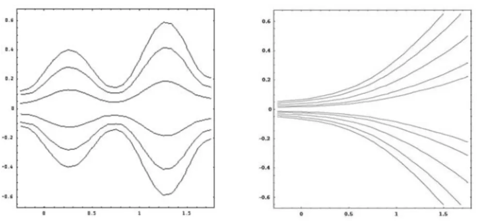
The stream line pattern has plotted for a wavy wall tube and exponentially diverging geometries for fixed values of coupling number N = 0.5, Hartman number Ha = 5.0 and asymptotic flux φ1 and is illustrated in Fig.2.
The effect of the coupling number on the axial velocity for a wavy wall tube has been depicted in Fig.3(a). It is observed that axial velocity increases near the center as the value of N increases. However, this trend is reversed near the boundary. This is because of the wavy nature of the boundary. It can also be
noted that the velocity in the case of viscous fluid (N → 0) is greater than in a micropolar fluid. Fig.3(b) shows the effect of coupling number N on micro-rotation. As the coupling number increases, the microrotation component also increases.
The variation of axial velocity and microrotation with wall absorption rate is shown in Fig.4(a) - (b). It is shown that an increasing in the wall absorption rate increases the axial velocity. It is also observed that as the wall absorption rate increases microrotation and the maximum of the microrotation shifts to-wards the boundary.
Fig. 5(a) and (b) shows the effect of Ha on the axial velocity and microrotation. It can be seen from Fig. 5(a) that the velocity, as it is expected, becomes small for large values of Ha. This happens because of the imposition of a magnetic field normal to the flow direction. This magnetic field gives rise to a resistive force and slows down the movement of the fluid in the pipe. Fig 5(b) shows decreasing microrotation with increasing Ha.
Fig. 6(a) shows the distribution of wall skin friction with axial distance for wavy wall geometry. The wall skin friction increases rapidly for the converging part but not significantly for the diverging part. An increase in wall absorption causes a general increase in wall skin friction. Fig. 6(b) shows the effect of absorption on wall skin friction for the exponentially diverging geometry. It is possible to see from the graph skin friction decreases as z increases. Also an increase in a wall absorption parameter increases the wall skin friction.
5. Conclusions
An analytic solution to the steady conducting micropolar fluid through a tube of varying cross-section under the influence of an applied uniform magnetic field has been obtained. It is shown that the axial velocity increases near the center and decreases near the boundary as the effects of the microstructure become significant. The velocity in case of micropolar fluid is always less than that of viscous fluid. Similarly, the microrotation increases, as the effects of the mi-crostructure become significant. It is also observed that increasing the magnetic field decreases the velocity and the micro rotation. Increasing the wall absorp-tion rate increases in the axial velocity and increases the skin fricabsorp-tion. The wall absorption rate increases microrotation and maximum of the microrotation shifts towards the boundary.
References
1. Hartmann, J and Lazarus, F. (1937), Hg-dynamics II: Experimental investigations on the flow of mercury in a homogeneous magnetic field, K. Dan. Vidensk. Selsk. Mat. Fys. Medd., 15(7), 1-45.
2. Mhone P.Y., and Makinde,O.D., Unsteady MHD flow with heat transfer in a diverging channel, Rom. J. Phys. Vol. 51, pp 963-975, 2006.
3. Rao A.R. and Deshikachar,K.S., MHD Oscillatory flow of blood through channels of variable cross section, Int. J. Engng. Sci., Vol. 24(10), pp1615-1628, 1986.
4. Verma, P.D.S., Kapoor, A. and Massoi, J. S. , Magnetic fluid flow in a two dimen-sional diverging channel, Int. J. Engng. Sci., Vol. 36, pp913- 919, 1998.
5. Tzirtzilakis,E.E., A mathematical model for blood flow in magnetic field, Phys. Fluids, Vol. 17, pp 077103-077115, 2005.
6. Manton, M. J., Low Reynolds number flow in slowly varying axisymmetric tubes, J. Fluid Mech., Vol. 43 pp 451-459, 1971.
7. Ramachandra Rao, A. and Devanathan, R, Pulsatile flow in tubes of varying cross-section, Z.A.M.P. Vo. 24, pp 203-213, 1973.
8. Schneck, D.J. and Ostrch, S., Pulsatile blood flow in a channel of small exponential divergence-I. The linear approximation for low mean Reynolds number, J. Fluids Eng., Vol. 97(3), pp353-360, 1975.
9. Srinivasacharya, D., M. Mishra and A. R. Rao, Peristalic pumping of a micropolar fluid in a tube, Acta Mechanica, Vol.161, pp165-178, 2003.
10. Makinde,O.D., Asymptotic approximations for oscillatory flow in a tube of varying cross-section with permeable isothermal wall, Rom. J. Phys. Vol.52, pp61-72, 2007. 11. Eringen, A. C., The theory of micropolar fluids, J. Math. Mech., Vol. 16, pp1-16, 1965.
12. Lukaszewicz, G, Micropolar fluids - theory and applications, Birkhauser, Boston, 1999.
Figures
Figure 2. The streamline pattern for (a) the sinusoidal flow geometry (b) for exponentially diverging geometry for
Figure 3. The effect of N on axial velocity (a) and microrotation (b) for m = 2, Ha = 5, z0= 1, φ1= 0.3, φ2= 2
Figure 4. The effect of φ1 on axial velocity (a) and microrotation
Figure 5. The effect of Ha on axial velocity (a) and microrotation (b) for m = 2, N = 0.5, z0= 1, φ1= 0.3, φ2= 2
Figure 6. Wall skin friction for different values of φ1 (a) wavy wall tube geometry (b) Exponentially diverging tube geometry for