Journal of Natural and Applied Sciences Volume 22, Issue 2, 528-535, 2018 Fen Bilimleri Enstitüsü Dergisi
Cilt 22, Sayı 2, 528-535, 2018
DOI: 10.19113/sdufbed.81545
The Effect of Nonwoven Electrospun PAN Nanofiber Mat on Mechanical and Thermal
Properties of Epoxy Composites
Mehmet Okan ERDAL1, Şakir YAZMAN2, Lokman GEMİ*1, Ahmet YAPICI3
1Necmettin Erbakan University, Meram Vocational School, 42090, Konya 2Selcuk University, Ilgın Vocational School, 42600, Konya
3Iskenderun Technical University, Eng. & Natural Sciences Faculty, Mechanical Engineering Dep., 31200, Hatay
(Alınış / Received: 02.11.2017, Kabul / Accepted: 11.05.2018, Online Yayınlanma / Published Online: 26.05.2018)
Keywords Electrospinning, Nanofiber, PAN, Composite, TGA, DSC
Abstract: In this study mechanical and thermal properties of epoxy resin reinforced with
different numbers of nanofiber layers which produced with electrospinning method was investigated. Solution of 10 wt% of polyacrylonitrile (PAN) in N,N-dimethylformamide (DMF) was used for electrospinning. The diameters of the obtained nanofibers were in the range of 380-420 nm. The average thickness of the produced nanofiber layer was about 200 µm. The special molds were prepared to produce the laminated composite plates. The tensile tests show that the using of nanofiber PAN layers increase the tensile force 34.54% and decrease the elongation 8.87% in comparison with neat epoxy. The fracture surfaces of the specimens were inspected by using optical and scanning electron microscopy (SEM). The thermal properties of the nanofiber layered composites were determined by thermo gravimetric analysis (TGA) and differential scanning calorimetry (DSC) analysis. It was observed that the glass transition temperature increased parallel to this as the number of PAN layers increased and rose up to 86ᵒC, while the thermal stability did not show much effect of PAN layers.
Örgülü Olmayan Elektrospin PAN Nanofiber Malzemenin Epoksi Kompozitlerin
Mekanik ve Termal Özelliklerine Etkisi
Anahtar Kelimeler Elektrospin, Nanofiber, PAN, Kompozit, TGA, DSC
Özet: Bu çalışmada elektrospin metodu ile üretilmiş farklı sayılardaki nanofiber takviyeli
tabakalı epoksi kompozitlerin mekanik ve termal özellikleri araştırılmıştır. Elektrospin işlemi için ağırlıkça %10 oranında poliakrilonitril (PAN) ve N,N dimetilformamid (DMF) çözeltisi kullanılmıştır. Elde edilen nanofiber çapları 380-420 nm aralığındadır. Üretilen nanofiber tabaka kalınlığı ortalama 200 µm’dir. Tabakalı kompozit plakaları elde etmek için özel kalıplar hazırlanmıştır. Çekme deney sonuçları nanofiber tabaka kullanımının çekme kuvvetini saf epoksiye oranla % 34.54 arttırdığı ancak uzamayı saf epoksiye oranla % 8.87 azalttığı belirlenmiştir. Numunelerin kırılma yüzeyleri optik ve taramalı elektron mikroskopu (SEM) ile incelenmiştir. Üretilen nanofiber tabakalı kompozitlerin termal özellikleri termal gravimetrik analiz (TGA) ve diferansiyel taramalı kalorimetre (DSC) analizleri ile belirlenmiştir. Camsı geçiş sıcaklığının PAN tabaka sayısı arttıkça buna paralel olarak arttığı ve 86 C ye kadar çıktığı, termal kararlılıkta ise PAN tabakalarının etkisinin çok fazla olmadığı görülmüştür.
1. Introduction
The epoxy resins are generally used as a matrix in composites materials and for their adhesive, chemical resistance, electrical insulation, low density and strong bond properties [1–3]. For achieving required mechanical and thermal properties, the approach of adding micro or nanofillers to polymer materials was applied [4,5]. The fibers which have diameters in nanometers show many good properties such as
flexibility, large surface area and high mechanical performance [6].
The nanofiber reinforced composite laminates are expected to have an improved strength, interlaminar fracture toughness, and delamination resistance towards static, impact and fatigue loadings. Especially, the nanofibrous reinforcement could be useful to prevent delamination from any source such as matrix cracks, notches, holes, bolted joints, etc. The
aim of nanofibers is to bond adjacent plies and to reduce the stress concentration without reduction of in-plane properties. The matrix between adjacent plies of the laminate can be reinforced with nanofibers [7,8]. There are several techniques to produce the nanofibers like jet blowing, melt blowing, co-extrusion, interfacial polymerization, electrospinning and others [9–14]. The electrospinning method has been widely used, among these techniques, to produce nanofibers of polymer and to produce also nanofibers filled with various nanoparticles [15–22].
Many researches have been carried out on the use of nanofibers in laminated composites to enhance the mechanical performance. But, there are a few papers in the literature [23–27] and additional researches are required to be carried out on the benefits of electrospun nanofibers in composite materials. This study presents an investigation of the use of polymeric nanofibrous layers to increase mechanical performance of the composite materials. The electrospun nanofibers of PAN layers are produced by electrospinning and placed in an epoxy. Three different layers were used to reinforce the epoxy. The fracture surface characterization is performed after the tensile test and the fiber breakage are investigated by using scanning electron microscopy (SEM).
2. Materials and Methods
2.1. Polymeric nanofibrous mats
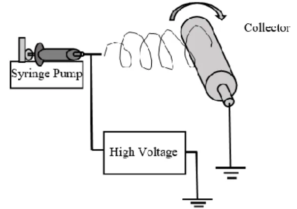
Polyacrylonitrile (PAN) and pure N,N-dimethylformamide (DMF) were provided from Sigma–Aldrich. PAN granules were dissolved at 10 wt% in DMF. PAN solution was stirred at room temperature and stirred with magnetic stirrer to ensure its dissolution. A horizontal setup was used for electrospinning processes. A syringe was used as injector. The electrospinning setup consisted of a high voltage power supply, a syringe pump, a syringe and a grounded electrode connected with rotating drum.
The parameters for electrospinning processes were chosen as 20 kV voltage, the distance between the collector and the tip of the spinneret 15 cm and the feed rate 2 mL/h. The electrospinning setup is shown in Figure 1. The nanofibers were collected on a rotating drum. The fiber diameter and its alignment mainly depend on the applied voltage, flow rate and distance between needle and collector [28].
2.2. Thermal properties
The curing behavior of the neat epoxy, 1, 2 and 3 layer reinforced epoxy is investigated using DSC (METTLERTOLEDO DSC 1 STAR System) in a
temperature range 20-350 °C. The thermal decomposition behavior of the composite specimens was carried out using TGA (METTLERTOLEDO TGA/DSC 2 STAR System) in the range 30– 800 °C.
Figure 1. Electrospinning setup
2.3. FTIR
Fourier transform infrared (FTIR) spectrum measurements were performed by means of a BRUKER-Vertex 70 spectrophotometer. All analyses were made in the range between 400 and 4000 cm-1
with a resolution of 2 cm-1 at room temperature. 2.4. Specimen fabrication
The composite laminate production is summarized in Figure 2. In composite materials Momentive MGS L285 (diglycidyl ether of bisaphenol A) was used as a resin and Momentive MGS H285 was used as a hardener. The PAN nanofibrous layers were placed in a special prepared mold then epoxy resin added. The mold is left for 24 hours at room temperature before it is placed into the oven for 80 °C temperature post cure for 15 hours.
Figure 2. The fabrication scheme used to create the
structure [29, 30]
Tensile testing of the composite specimens was carried out according to ASTM D638 on a Shimadzu model 10 kN universal testing machine. The experimental studies were repeated five times for each parameter.
3. Results and Discussion
3.1. Characterization of nanofibers
The morphology and structure of the PAN nanofibers were analyzed by SEM. Electrospun non-woven mats
were found to be 200 ± 10 µm thick and kept at room temperature for 24 h. The SEM image of electrospun fabric is shown in Figure 3. Fibers diameter (400 ± 20 nm) was measured by using image acquisition software.
(a) Electrospun mat
(b) Nanofiber of PAN
Figure 3. Morphology of electrospun PAN fibers
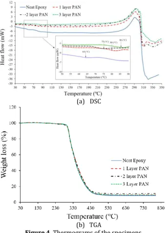
3.2. DSC and TGA studies on the composites
As shown in Figure 4(a), DSC was used to analyze the neat epoxy and three different PAN layers/epoxy composites. The glass transition heat of epoxy resin Tg shows an endothermic peak at 64.33 °C. The glass
transition temperature (Tg), reaction enthalpy (ΔH)
and heat capacity (Cp) temperature for each
composite are shown in Table 1. Figure 4(b) shows TGA results of neat epoxy and reinforced epoxy with various layers of PAN. The higher mass loss rate occurs at temperatures between 297 °C and 309 °C.
Table 1. The glass transition temperature (Tg), reaction
enthalpy (ΔH) and heat capacity (Cp) temperature of
samples. Specimens Tg (°C) ΔH(j/g) Cp (j/g°K) Neat Epoxy 64 382 0.278 1 Layer PAN 80 285 0.142 2 Layer PAN 75 294 0.246 3 Layer PAN 86 290 0.201
The thermal parameters like Td5- the initial
decomposition temperature (the temperature of 5% weight loss), Tonset- the temperature at which the
degradation started, Td-degradation temperature and
Tendset- the temperature at ending process were
determined by the TGA as shown in Table 2.
(a) DSC
(b) TGA
Figure 4. Thermograms of the specimens
Table 2. TGA parameters of samples obtained from TGA
thermograms
Specimens T(°C) onset T(°C) endset (°C) Td5 (°C) Td Char (%) at 800°C
Neat Epoxy 175 628 299 306 8.5
1 Layer PAN 180 610 298 307 9.6 2 Layer PAN 170 584 297 308 10.9 3 Layer PAN 180 630 299 309 9.3 The results show that Tg values increase with the
increasing of PAN layers compared to neat epoxy. The PAN layers show the catalytic effect in epoxy, they reduce the free space between macromolecular structures in the interface of PAN-epoxy. They increase also the crosslink intensity and decrease the unsaturated bonds. Similarly, by increasing the PAN layers the values of ΔH and Cp decrease. This means
that the PAN layers in the composite absorb heat and act as a heat sink in the structure [31,32]. Cp generally
related with the molecular mobility, the increase in molecular mobility gives higher ΔCp values.
Eventually increasing in Tg values cause decreasing in
molecular mobility and Cp values.
Figure 4. and Table 1-2 show that there is no remarkable effect on thermal stability of epoxy with increasing the PAN layers.
3.3. FTIR spectra
The FTIR spectrum of nanofiber layers of PAN reinforced resin are depicted in Figure 5. and FTIR results for pure resin is given also for comparison. FTIR spectra of the resin with PAN layers prepared
was used to clarify the possible interaction between the epoxy resin and PAN layers. In the FTIR spectrum of the resin with PAN layers and without layers the characteristic absorption of the nanofibers based PAN layers was superposed over the pure epoxy resin structure.
Figure 5. FTIR spectra of neat epoxy and nanofiber PAN
layers
Chemical structure of epoxy resin based on bisphenol A, amino curing agent and PAN are given in Figure 6. Stretching vibration of different chemical groups of the neat epoxy and nanofiber PAN layers are given in Table 3 [33,34].
Two characteristic peaks at 2239 and 1447 cm−1 attributed to the –C N stretching vibration
and –CH2 scissoring vibration of PAN polymer
structure are not observed. No shifts can be detected in the fundamental vibration frequencies resulting from composite formation. Furthermore, the spectrum of nanofibers based PAN did not show any appearance or disappearance of bond formation between resin and PAN layers, which indicates that no new chemical bonds are formed in the interaction. This situation supports the possible intermolecular interactions such as hydrogen binding, van der walls attractions and weak or strong dipol-dipol interactions between resin and PAN materials.
3.4. Tensile properties
The typical load-displacement diagram of the pure epoxy and three nanocomposites with the
reinforcement content of one, two and three-layered plates are illustrated in Figure 7. The presented results show obvious changes in the mechanical behavior of the epoxy under tensile loading. The curves of reinforced epoxy show increasing of the value of load with a decrease in the plastic region comparing to the neat epoxy (Figure 8 (a-d)).
Figure 6. Chemical structure of a) epoxy resin based on
bisphenol A, b) amino curing agent and c) PAN
Table 3. Stretching vibration of different chemical groups
of the neat epoxy and nanofiber PAN layers
Bands (cm-1) Assignment
3340-3500 Hydroxyl (–OH) stretching 3060 Symmetric stretching of C–H of the
oxirane ring
2960-2870 Alkyl units (C–H and –CH2) stretching
2349 –CO2
1607 C=C stretching of aromatic ring 1509 C–C stretching of aromatic ring
1236 –C–C–O–C stretching
1036 C–O–C stretching of ethers
828 Aromatic absorbance
Figure 7. Tensile graphs of the composites with different
layer numbers
The tensile test results of epoxy and composites are given in Figure 9. The highest improvements of these four graphs were achieved for two-layered PAN composite with enhancement of 34.54% in tensile strength while elongation decreases 8.87% compared with neat epoxy.
(a) R-NH2
(b)
a) Neat epoxy
b) 1 Layer PAN
c) 2 Layer PAN
d) 3 Layer PAN
Figure 8. The yield points and plastic deformation regions
of neat epoxy and composites in the tensile graphs.
3.5. Structural and morphological
characterization after tensile tests
Figure 10. shows cross-sectioning and optical microscope study after tensile tests. The Figures
10(b-d) show that PAN layers are straight, tight and bonded perfectly with epoxy.
(a) Ultimate tensile stress
(b) Elongation at break (%)
Figure 9. Tensile tests results
(a) neat epoxy
(b) 1 layer PAN
(c) 2 layer PAN
(d) 3 layer PAN
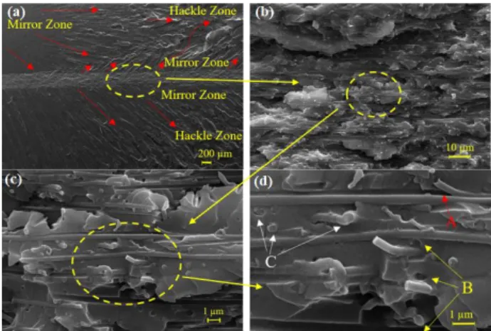
SEM fractographs were taken after failure of the specimens at various points. The matrix cracks inclined towards the direction of crack propagation Figure 11(a-b).
(a)
(b)
Figure 11. SEM pictures of fractured surfaces of neat epoxy
(a) X21 (b) X500 magnification.
Figure 12. shows the detailed PAN-epoxy bond and crack propagation lines on cross-sectioning surface of the specimen. It is obvious that the PAN layer bonded perfectly with epoxy. Generally, mirror, mist and hackle three different fracture zones observed in case of thermosetting polymers [35]. The three fracture zones can be seen on the fracture surface of neat epoxy and PAN reinforced epoxy as shown in Figure 11(a) and Figure 12(a). The crack propagation direction is indicated by red color arrows. At the beginning of the fracture the crack grows very slowly and creates very smooth surface (mirror zone) [36,37]. Then the crack accelerates and creates a little rougher region (mist zone). When the crack reaches its maximum speed a very rough region occurs (hackle zone). Investigating Figure 12(a), crack propagates in PAN layer faster than in epoxy from left to right and creates mirror zone (about ± 45 crack lines) around the PAN layer. This result is compatible with the result of tensile test. Because the catalytic effect in the interface of PAN- epoxy increases the crosslink intensity and decreases the unsaturated bonds making the composite plate brittle than neat epoxy and increasing the strength (Figure 7). Figure 12(d) shows also the debonding and pullout of the nanofiber of PAN from epoxy and nanofiber breakage after tensile test [38,39].
Figure 12. SEM images of tensile fracture surface of 1 layer
PAN-epoxy (a) X20 (b) X1000 (c) X5000 (d) X10000 magnification; where A-debonding, B-pullout, C-breakage.
4. Conclusions
The nanofiber PAN layers were produced using electrospinning by dissolving PAN in DMF solution. PAN layers are placed in epoxy using special mold. Thermal and mechanical properties of neat epoxy, one-layer PAN, two-layer PAN and three-layer PAN reinforced composites plates were investigated. DSC results show that the PAN layers/epoxy composites have slight higher temperature range comparing to neat epoxy. TGA thermograms show that there is no remarkable effect on thermal stability of epoxy with increasing the PAN layers. As a result of tensile tests, PAN layers increase the tensile stress but they decrease the elongation. Two-layered composite gives the highest tensile load value.
Acknowledgment
The authors thank Necmettin Erbakan University Science & Technology Practice and Research Center (BITAM) and Scientific Research Project Funding office (BAP-Project number: 171228002) for their financial support and Selcuk University Department of Metallurgical and Materials Engineering Lab.
References
[1] Ueki, T., Nishijima, S., Izumi, Y. 2005. Designing of epoxy resin systems for cryogenic use. Cryogenics, 45(2), 141–8.
[2] Kang, S., Hong, SI., Choe, CR., Park, M., Rim, S., Kim, J. 2001. Preparation and characterization of epoxy composites filled with functionalized nanosilica particles obtained via sol–gel process. Polymer, 42(3), 879–87.
[3] Shan, X., Huang, C., Yang, H., Wu, Z., Li, J., Huang, R., et al. 2015. The thermal expansion and tensile properties of nanofiber-ZrW2O8 reinforced epoxy resin nanocomposites. Phys Procedia, 67, 1056–61.
[4] Chen, IH., Wang, CC., Chen, CY. 2010. Preparation of carbon nanotube (CNT) composites by
polymer functionalized CNT under plasma treatment. Plasma Process Polymers, 7(1), 59– 63.
[5] Li, J., Wu, Z., Huang, C., Liu, H., Huang, R., Li, L. 2014. Mechanical properties of cyanate ester/epoxy nanocomposites modified with plasma functionalized MWCNTs. Composites Science and Technology, 90,166–73.
[6] Huang, ZM., Zhang, YZ., Kotaki, M., Ramakrishna, S. 2003. A review on polymer nanofibers by electrospinning and their applications in nanocomposites. Composites Science and Technology, 63(15), 2223–53.
[7] Palazzetti, R., Zucchelli, A., Gualandi, C., Focarete, ML., Donati, L., Minak, G., et al. 2012. Influence of electrospun Nylon 6,6 nanofibrous mats on the interlaminar properties of Gr-epoxy composite laminates. Composite structures, 94(2), 571–9. [8] Kim, JS., Reneker, DH. 1999. Mechanical
properties of composites using ultrafine electrospun fibers. Polymer Composites, 20(1), 124–31.
[9] Borkar, S., Gu, B., Dirmyer, M., Delicado, R., Sen, A., Jackson, BR., et al. 2006. Polytetrafluoroethylene nano/microfibers by jet blowing. Polymer, 47(25), 8337–43.
[10] Ellison, C.J, Phatak, A., Giles, DW., Macosko, CW., Bates, FS. 2007. Melt blown nanofibers: Fiber diameter distributions and onset of fiber breakup. Polymer, 48(11), 3306–16.
[11] Wang, J., Langhe, D., Ponting, M., Wnek, GE., Korley, LT., Baer, E. 2014. Manufacturing of polymer continuous nanofibers using a novel co-extrusion and multiplication technique. Polymer, 55(2), 673–85.
[12] Zhang, X., Zhu, J., Haldolaarachchige, N., Ryu, J., Young, D. P., Wei, S., Guo, Z. 2012. Synthetic process engineered polyaniline nanostructures with tunable morphology and physical properties. Polymer, 53(10), 2109-2120. [13] Zhao, S., Wu, X., Wang, L., & Huang, Y. 2004.
Electrospinning of ethyl–cyanoethyl cellulose/tetrahydrofuran solutions. Journal of Applied Polymer Science, 91(1), 242-246. [14] Yang, F., Murugan, R., Wang, S., Ramakrishna, S.
2005. Electrospinning of nano/micro scale poly (L-lactic acid) aligned fibers and their potential in neural tissue engineering. Biomaterials, 26(15), 2603-2610.
[15] Bhardwaj, N., Kundu, S. C. 2010. Electrospinning: A fascinating fiber fabrication technique. Biotechnology Advances, 28(3), 325-347. [16] Jeun, JP., Kim, YK., Lim, YM., Choi, JH., Jung, CH
KP., Yc, N. 2007. Electrospinning of Poly (L-lactide-co-D, L-lactide). Journal of Industrial and Engineering Chemistry, 13(4), 592-596.
[17] Demir, MM., Yilgor, I., Yilgor, E., Erman, B. 2002. Electrospinning of polyurethane fibers. Polymer, 43(11), 3303-3309.
[18] Zhu, J., Wei, S., Rutman, D., Haldolaarachchige, N., Young, DP., Guo, Z. 2011. Magnetic polyacrylonitrile-Fe@ FeO nanocomposite fibers-Electrospinning, stabilization and carbonization. Polymer, 52(13):2947–2955. [19] Zhu, J., Chen, M., Qu, H., Wei, H., Guo, J., Luo, Z.,
Guo, Z. 2014. Positive and negative magnetoresistance phenomena observed in magnetic electrospun polyacrylonitrile-based carbon nanocomposite fibers. Journal of Materials Chemistry C, 2(4), 715-722.
[20] Tomczak, N., Gu, S., Han, M., van Hulst, NF., Vancso, G.J. 2006. Single light emitters in electrospun polymer nanofibers: Effect of local confinement on radiative decay. European polymer journal, 42(10), 2205-2210.
[21] Qu, H., Wei, S., Guo, Z. 2013. Coaxial electrospun nanostructures and their applications. Journal of Materials Chemistry A, 1(38), 11513-11528. [22] Almuhamed, S., Khenoussi, N., Bonne, M.,
Schacher, L., Lebeau, B., Adolphe, D., Brendlé, J. 2014. Electrospinning of PAN nanofibers incorporating SBA-15-type ordered mesoporous silica particles. European polymer journal, 54, 71-78.
[23] Shivakumar, K., Lingaiah, S., Chen, H., Akangah, P., Swaminathan, G., Russell, L. 2009. Polymer nanofabric interleaved composite laminates. AIAA journal, 47(7), 1723-1729.
[24] Sihn, S., Kim, RY., Huh, W., Lee, KH., Roy, AK. 2008. Improvement of damage resistance in laminated composites with electrospun nano-interlayers. Composites Science and Technology, 68(3-4), 673-683.
[25] Liu, L., Huang, ZM., He, CL., Han, X. 2006. Mechanical performance of laminated composites incorporated with nanofibrous membranes. Materials Science and Engineering: A, 435, 309-317.
[26] Zhang, J., Lin, T., Wang, X. 2010. Electrospun nanofibre toughened carbon/epoxy composites: Effects of polyetherketone cardo (PEK-C) nanofibre diameter and interlayer thickness. Composites Science and Technology, 70(11), 1660-1666.
[27] Lin, S., Cai, Q., Ji, J., Sui, G., Yu, Y., Yang, X., Deng, X. 2008. Electrospun nanofiber reinforced and toughened composites through in situ nano-interface formation. Composites Science and Technology, 68(15-16), 3322-3329.
[28] Akangah, P., Lingaiah, S., Shivakumar, K. 2010. Effect of Nylon-66 nano-fiber interleaving on impact damage resistance of epoxy/carbon fiber composite laminates. Composite Structures,
92(6), 1432-1439.
[29] Erdal, MO., Yazman, Ş., Gemi, L., Yapıcı, A. 2015. Çok Katmanlı Nanoelyaf Takviyesinin Epoksi Reçinenin Mekanik Özelliklerine Etkisinin İncelenmesi. Mühendislikte Yeni Teknolojiler Sempozyumu, 22-23 Ekim, Bayburt, 30-35. [30] Jin, F-L., Ma, C-J., Park, S-J. 2011. Thermal and
mechanical interfacial properties of epoxy composites based on functionalized carbon nanotubes. Materials Science and Engineering: A, 528(29-30), 8517-8522.
[31] Yapici, A., Özkan, V., Yıldız, M., Erdal, M., Gemi, L., Yazman, Ş. 2016. The Effect of Nylon 6.6 Nanofiber Layers on Mechanical Properties of Epoxy. The International Journal of Engineering and Science, 5(11), 86-89.
[32] Yapici, A., Özkan, V., Yıldız, M., Erdal, M., Gemi, L., Yazman, Ş. 2016. The nylon 6.6 nanofiber layers’ effect on mechanical properties of epoxy. 12th
International Nanoscience and Nanotechnology Conference, 03-05 June Kocaeli, 152.
[33] Tait, J., Davies, G., McIntyre, R., Yarwood, J. 1997. FTIR-ATR studies of interfacial interactions in epoxy resin/polymer laminate structures. Vibrational spectroscopy, 15(1), 79-89.
[34] Nacimiento, F., Alcántara, R., González, JR., Tirado, JL. 2012. Electrodeposited polyacrylonitrile and cobalt-tin composite thin
film on titanium substrate. Journal of The Electrochemical Society, 159(7), A1028-A1033. [35] Goyat, M., Suresh, S., Bahl, S., Halder, S., & Ghosh,
P. 2015. Thermomechanical response and toughening mechanisms of a carbon nano bead reinforced epoxy composite. Materials Chemistry and Physics, 166, 144-152.
[36] Gemi, L., Yazman, Ş., Uludağ, M., Dışpınar, D. 2017. The effect of 0.5 wt% additions of carbon nanotubes & ceramic nanoparticles on tensile properties of epoxy-matrix composites: A comparative study. Materials Science and Nanotechnology, 1(2), 15-22.
[37] Yazman, Ş., Gemi, L., Uludağ, M., Dışpınar, D. 2015. Investigation of The Effect of Carbon Nanotube Ratio on The Wear Behavior of Carbon Nanotube/Epoxy Nanocomposites. International Journal of Enhanced Research in Science, Technology & Engineering, 4(7), 201-207. [38] Güneş, E., Erdal, M., Gemi, L. 2017. The effect of
nanofiber on the biological traits of Drosophila Melanogaster. Sakarya University Journal of Science, 26(6), 1612-1617.
[39] Morkavuk, S., Köklü, U., Bağcı, M., Gemi, L. 2018. Cryogenic machining of carbon fiber reinforced plastic (CFRP) composites and the effects of cryogenic treatment on tensile properties: A comparative study. Composites Part B: Engineering, 147, 1-11.