Lyotropic Liquid Crystalline Mesophase of Sulfuric Acid
−Nonionic
Surfactant Stabilizes Lead(II) Oxide in Sulfuric Acid Concentrations
Relevant to Lead Acid Batteries
Can Berk Uzundal,
†Fadime Mert Balci,
†Burak Ulgut,
*
,†and Ömer Dag
*
,†,‡†Faculty of Science, Department of Chemistry and‡UNAM-Institute of Materials Science and Nanotechnology, Bilkent University,
06800 Ankara, Turkey
ABSTRACT: Concentrated sulfuric acid (SA) and nonionic surfactant (C12H25(OCH2CH2)10OH, C12E10) form lyotropic liquid crystalline (LLC) mesophases in a broad range of SA concentrations; the SA/C12E10mole ratio may vary from 2 to 11 in the LLC mesophases in the presence of a small amount of water. The mesophase is hexagonal at low SA concentration and cubic at higher concentrations. Three different composi-tions were prepared (one hexagonal and two cubic) with the SA/C12E10mole ratio of 2.5, 6, and 9, denoted as 2.5LC, 6LC,
and 9LC, respectively. They all display electrochemical SA activity in Pt and Pb systems. Most interestingly, they show the electrochemical formation of stable PbO species in a deeply acidic medium as evidenced by the X-ray diffraction, cyclic
voltammetry, and linear sweep voltammetry experiments. The preferable properties of PbO over PbSO4for lead acid batteries (LABs) make it uniquely positioned as a superior gel electrolyte for the LABs that would mitigate sulfation.
■
INTRODUCTIONHygroscopic species, such as salts and acids, can be used as solvents in the assembly of surfactants into the lyotropic liquid crystalline (LLC) mesophases.1−4 Acids, such as H3PO4 and
H2SO4(sulfuric acid, SA), which have very low vapor pressure, form stable LLC mesophases in a very broad range of acid concentrations.3,4Notice also that SA is a strong acid and forms mesophases upon addition of a small amount of water. The mixture of concentrated SA and surfactant is a liquid thatflows when it is spread over a substrate. However, in a short period, it absorbs enough ambient water to form a rigid and stable LLC mesophase. The typical water uptake of a stable SA/C12E10
LLC phase changes with the SA concentration and varies from 2.3 to 4.3 water/SA when the SA/C12E10ratio increases from 2 to 12.4Note also that the mesophase is two-dimensional (2D) hexagonal up to around 3.5 SA/C12E10 and becomes micelle
cubic above this ratio. The cubic mesophases are always better conductors than the 2D hexagonal ones due to the three-dimensional (3D) connectivity of the ionic species in the mesophase.5The SA/C12E10mesophases have excellent proton conductivities that increase with increasing SA concentration in the media. As the SA/C12E10ratio increases from 2 to 11, the
proton conductivity increases from 2 to 19 mS/cm.4
Acid−surfactant and salt−surfactant mesophases have great potential to be used as gel electrolytes in various electro-chemical devices such as batteries, solar cells, supercapacitors, electrochromic devices, and so on.6−11The LLC mesophases have already displayed excellent conductivity that finds application in many electrochemical systems.2,3,6−11 In this
report, this phase and its application in lead acid batteries (LABs) will be investigated.
Recent industry projections predict that LABs will hold their dominant position in the energy storage market in the near future, owing to their current standing applications such as starter batteries in cars and uninterrupted power supplies at various institutions where low cost, reliability, and relative safety of the chemistry make them stand out.12 Applications where safety is the most critical component, as is the case in military applications, LABs’ proven safety record makes them indispensable. For example, LABs are used to buffer the output of the reactor in nuclear submarines. The U.S. Department of Defense has recently awarded a contract worth U.S.$31 million to improve the batteries for this application.13On theflip side, SA industry is thriving, owing to the established market in LABs, which use SA as an electrolyte. The total annual consumption is estimated to be U.S.$85 billion.14 Therefore, new developments that improve LABs would have substantial industrial and commercial impact, even though the chemistry is mature and well-known.
In the charged state, the positive electrode of a LAB consists of Pb(IV) species and the negative electrode consists of Pb(0) species. At the end of discharge, both electrodes attain Pb(II) species. The main electrochemical reactions are as follows (forward reaction indicates discharge)15
Received: June 21, 2017
Accepted: July 11, 2017
Published: July 20, 2017
Article http://pubs.acs.org/journal/acsodf
Attempted solutions to combat sulfation in the literature involve the addition of conductive additives to the electrode material or involve composite approaches, where current demands that would otherwise cause deep discharge are drawn from an ultracapacitor instead of the LAB.17,18
At the end of the discharge cycle, if the Pb(II) species formed were oxides and not sulfates, it would be advantageous both in terms of the kinetics of electrode reactions and conductivity. The Pb(II) oxide species is known to be more advantageous both in terms of conductivity and kinetics than sulfate.15 Therefore, during the industrial production of LABs, the active material production starts from PbO and is mixed with enough water to produce the tribasic PbSO4(PbSO4·3PbO), which is
more stable in acid solutions compared with PbO. During the actual battery operation, the Pb(II) species generated on both positive and negative electrodes are the sulfate because that is the stable form according to the well-known Pourbaix diagram at any pH below 8, as shown inFigure 1.15,19In 6 M H2SO4, which is typically used in LABs, the oxide species is not expected to be stable.
LABs using gel electrolytes are already commonplace.20,21 The gels employed are made up of colloidal silica that is cross-linked using the acid-based dehydration.20,21 The major advantage of using a gel-based electrolyte is the mitigation of
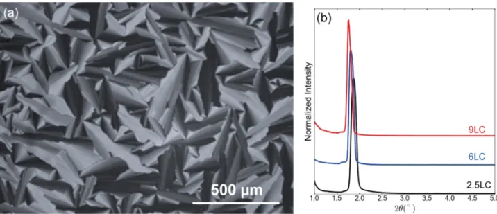
(1:2.5:7.5, 1:6:18, and 1:9:27 mole ratios, respectively) to obtain the liquid crystalline gel phases. The 2.5 SA/C12E10 sample (denoted 2.5LC) displays a focal conic fan texture, characteristic of the 2D hexagonal columnar phase (Figure 2a). The other two samples of 6 and 9 SA/C12E10 mole ratios
(denoted as 6LC and 9LC, respectively) are dark between the crossed polarizers. All of the three samples diffract at small angles, with a slight shift to the lower angles with increasing SA amount in the samples; seeFigure 2b. Even though there is a single line in the diffraction patterns, the mesophase is micellar cubic in 6LC and 9LC.4 Notice also that the surfactant molecules are not stable in concentrated SA solutions and slowly undergo dehydration to form carbon nanoparticles. A mixture of concentrated SA and surfactant is a transparent colorless liquid, which slowly turns into dark brown over time. The carbonization process is halted in the presence of a small and stoichiometric amount of water in the LLC media. For instance, if a solution of concentrated SA and C12E10 (undergoes slow carbonization) is exposed to ambient laboratory condition, the mixture slowly absorbs enough water to transform to a stable gel phase, where the C12E10
molecules are stable.
Two separate studies have been performed to investigate the proton activity or the apparent pH of the LC systems. Both tests are picked from the electrochemistry literature on well-established experiments using SA solutions as electrolytes. The two experiments picked are the well-known polycrystalline Pt in SA CV experiment and the standard polarization resistance experiment on stainless steel. The CV of a 5 M aqueous SA solution, 6LC, and 9LC using Pt as the working electrode (WE) are shown in Figure 3a (2.5LC data not shown for clarity). CVs clearly show that both 6LC and 9LC have electrochemically active SA and display characteristic peaks of Pt in the SA systems.22,23This is a clear indication that the SA inside the LLC mesophases is electrochemically active, and that the cyclic voltammetric features of hydrogen adsorption/ desorption and the oxide formation/reduction are feasible inside the LLC mesophases. The peak onsets shift to more positive potentials on the hydrogen desorption/adsorption in case of LLC phases than in the 5 M SA aqueous solution. This shift, roughly 40 mV, indicates that the activities of H+ are slightly higher in the LLC mesophases than in the 5 M aqueous SA solution. The corrosion rate measurements of stainless steel in the LLC phases indicate a similar level of activity. In the literature,24 it is well-established that the rate of corrosion increases with increasing concentration until 6 M and decreases with further increase from 6 M SA to a concentrated SA. As
Figure 1.Well-known Pourbaix diagram for Pb species in SA solution. Reprinted from ref19with permission.
Figure 2.Polarized optical microscope (POM) image of 2.5LC (a) and small-angle XRD patterns of 9LC, 6LC, and 2.5LC, top to bottom (b). XRD patterns are offset for clarity.
Figure 3.Pt electrode experiments (a) and the corrosion rate experiments (b) to confirm the electrochemical activity and to establish an analogy to aqueous solutions of SA.
may have an impact on the preparation and preservation of the electrodes in the traditional LABs. As a result, we mainly focus on the oxidation of Pb to PbO/PbSO4 and subsequent
reduction of the latter to Pb metal, which is the negative electrode half-reaction in the LABs.
A typical Pb CV of a 5 M SA is shown inFigure 4. It displays an oxidation peak due to oxidation of Pb to PbSO4 on the
oxidation side and a much smaller reduction peak attributed to the reduction of PbSO4 back to Pb, as also shown in the
literature.25−27 The weak reduction peak is attributed to the formation of large nonconducting PbSO4 crystallites that
cannot be reduced.15 The corresponding CVs in 2.5LC and 9LC mesophases display distinctively different voltammograms. Notice that the single oxidation peak in the 5 M SA becomes two in the SA/C12E10samples. We focus our attention on 9LC due to its higher SA activity (as confirmed by the polarization resistance and the Pt electrode experiments). Looking at the data more carefully, we notice that the oxidation peak not only has a shoulder but also a new reduction peak, which is distinct from the reduction of PbSO4present. This shows the unique effect of SA/C12E10 mesophases on the Pb redox products.
There is clearly a new species that gets reduced at a distinctly more positive potential than sulfate. Furthermore, the ratio of PbSO4reduction peak current to the Pb oxidation peak current is also markedly larger in the LLC system at 1 mV/s compared with the ratio in the 5 M SA solution, suggesting a more reversible reaction, as shown inTable 1. The LLC system leads to smaller PbSO4products that are more readily reduced than
their counterparts formed in the aqueous solution.
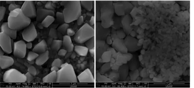
Shoulder peaks can only be resolved at low sweep rates, such as 1 mV/s, indicating the slow kinetics of the process. To identify the new species formed in the LLC system, we conducted chronoamperometry (CA) experiments at various potentials to growfilms over the Pb electrode and characterized them using the XRD and scanning electron microscopy (SEM) (Figure 5). First inspection of the Pb electrodes after this process shows a distinct difference between the electrodes
α-PbO and β-PbO with a higher concentration ofβ-PbO) are observed in the pattern obtained from the 9LC electrode. The SEM images of these two electrodes, prepared using 9LC and 5 M SA, display quite different surface morphologies. Crystalline surface species over the surface of the electrode used in 9LC are more uniform and much smaller than those on the electrode used in 5 M SA, consistent with the electrochemical and XRD results; see
Figures 5and6. One explanation for this observed result is that the PbO formation on the surface of the Pb electrode is stable when it is in contact with the LLC phase opposed to the high instability in the SA solution.
To test this hypothesis, the resulting PbO/PbSO4grown on the Pb electrode using 9LC was submerged in the 5 M SA solution. The loss of the initial yellow-brown color hints at the instability of the formed oxide in the solution phase. The linear sweep voltammogram (LSV) of PbO/PbSO4after submerging in the 5 M SA solution (for 24 h), showing a single reduction peak attributed to the lead sulfate reduction back to lead, is shown in Figure 7b. Similarly, the LSV of a pristine PbO/ PbSO4shows a shoulder peak (Figure 7a), thus suggesting the presence of another species, which is not stable in the aqueous SA solution, in the coating. Further cycling the potential for this lead strip did not yield the same shoulder peak as shown in
Figure 7c. These results clearly show that the oxide species, as expected, are not stable in the solution phase, whereas they do form in LLC mesophases and are stable.
The reduction peak that is attributed to the reduction of PbO was also observed in the aqueous systems only when the CV was performed to very oxidizing potentials that also lead to PbO2. This behavior was also shown in the literature.26,27 Under these conditions, the two reduction peaks are present, and the peak at the more positive potential is attributed to the reduction of PbO. In the current work, the reduction peak attributed to PbO is visible even when potentials are never swept to as positive potentials.
■
CONCLUSIONSSA forms LLC mesophases with a nonionic surfactant (such as C12E10) and displays the electrochemical activity similar to that of aqueous SA. The SA/C12E10mesophases, however, produce
stable PbO in addition to PbSO4 during the oxidation or discharge of LABs, which can be utilized industrially. It is likely that the PbO always forms during oxidation of lead in the discharge of LABs. However, PbO converts into insoluble, nonconducting PbSO4 in ordinary LABs due to its high instability in aqueous SA solution. The formation and high Table 1. PbSO4Oxidation and Reduction Peak Currents at 1
mV/s Sweep Rate electrolytes
oxidation peak current (μA)
reduction peak current (μA) ratio (%) 9LC 107.8 101.6 94.2 6LC 225.2 46.08 20.5 5 M H2SO4 979.6 270.5 27.6
stability of PbO in the case of LLC as the electrolyte would be a vital improvement for the development of gel electrolyte LABs over traditional LABs.
One possible explanation for this effect is that the contact between the electrode and electrolyte is hindered by the surfactant molecules. This stabilizes the PbO formed over the electrode surface. Otherwise, a direct contact of the SA solution with the electrode surface is detrimental for the PbO particles and decomposes them into PbSO4. The mesophases are
electrochemically active but chemically protective for the formation and stability of PbO.
■
EXPERIMENTAL SECTIONPreparation of LLC Gels. In a general procedure, the LLC gels were prepared by varying SA/C12E10 (SA is H2SO4 and
C12E10is 10-lauryl ether, C12H25(OCH2CH2)10OH) mole ratio
from 2.5 to 9 (2.5 low, 6 intermediate, and 9 high) and keeping the SA/H2O mole ratio constant at 3.0. For example, the
sample with a 9 SA/C12E10mole ratio was prepared as follows: first, 9 mmol of SA (1.038 g, 85% SA) was added to 27 mmol of water (0.486 g) and stirred a few seconds by magnetic stirrer. Afterward, 1 mmol of C12E10(0.626 g) was added to the above clear solution. The resulting mixture was homogenized by using a vortex mixer and then heated in the heat bath at 80°C for 48 h to obtain the clear gel (denoted as 9LC). The other two compositions, 2.5LC and 6LC, were prepared using 0.288 g SA, 0.135 g water, and 0.626 g C12E10 and 0.692 g SA, 0.314 g
water, and 0.626 g C12E10, respectively, following the same procedure. For characterization, the gels were dissolved in water and then coated on glass slides via spin coating at 1000 rpm. For electrochemistry, the gel formed was used directly in a vial.
Figure 5.SEM images of a lead strip after 10 h of CA at−0.91 V (vs Ag2SO4) (left) in 5 M H2SO4and in (right) 9LC.
Figure 6.XRD patterns of as-conditioned Pb electrodes (a) and after oxidation (b). The black curves (I) show the results in the LC and the red curves (II) show the aqueous solution. XRD patterns are offset for clarity.
Measurements. The XRD patterns were recorded using a Rigaku Miniflex diffractometer equipped with a high-power Cu Kα source operating at 30 kV/15 mA and a wavelength of 1.5405 Å. The POM images were obtained in the transmittance mode by using a Zeiss Axio Scope.A1 polarizing optical microscope. The SEM images were recorded using a ZEISS EVO-40 SEM operated at 15 kV.
All of the electrochemical experiments were conducted on a Gamry Interface 5000E potentiostat. The Pt CVs were conducted in a three-electrode cell with a 6 mm diameter Pt WE, a graphite counter electrode (CE), and Ag/Ag2SO4as a
reference electrode (RE).
Polarization resistance experiments were conducted in a two-electrode geometry, using stainless steel two-electrodes fitted through a Teflon frit. Each stainless steel electrode had an area of 0.48 cm2. Voltage sweeps were chosen to be±0.015 V versus open-circuit potential (Eoc) with a sweep rate of 0.10
mV/s. A 10 min equilibration time followed by 5 h experiment was done. The value of the self-exchange current was obtained by a linearfit to the data near 0 V (vs Eoc).
The Pb CVs were collected in a three-electrode cell with a Pb WE strip of 2 cm× 6 cm, a graphite CE, and an Ag/Ag2SO4as RE. The electrode area of the Pb WE was normalized by an epoxy resin such that only a 6 mm diameter circular region of Pb was exposed to the solution/liquid crystal. Moreover, the surface of the Pb WE was conditioned before each sweep experiment at sufficiently negative potentials to reduce all of the electrode surface. Reported Pb in H2SO4CVs were, in all of the cases, in a steady state; at least 12 cycles were done and no appreciable change was observed in subsequent cycles.
Ag/Ag2SO4RE was fabricated following a literature report.28
Briefly, an Ag wire 1 mm in diameter and 3.2 mm long was oxidized under a constant current of 80 μA for 3 h in a degassed 0.1 M Na2SO4. The formation of gray-white Ag2SO4
as opposed to the brown oxide was observed. Facile ion transport across the ion-exchange membrane of RE and liquid
crystal was confirmed by impedance measurements (measured Z = 346.5 Ω). The stability of the fabricated electrode was confirmed by Pt in H2SO4 CVs over a 24 h period. The potential calibration was done by measuring and monitoring the open-circuit potential of a two-electrode system, in which the working side is a Ag/AgCl RE and the reference side is the Ag/Ag2SO4RE (Eoc=−0.407 V).
Chronoamperometry experiments were done at various potentials for 1, 5, and 10 h for both 9LC and 5 M H2SO4 solutions after conditioning at appropriate negative potential and linear sweep (at 1 mV/s) to the potential of interest. A three-electrode setup consisting of Pb WE, graphite CE, and the previously prepared Ag/Ag2SO4 RE was used. The lead strips were washed gently with deionized water and the SEM images were taken.
■
AUTHOR INFORMATIONCorresponding Authors
*E-mail:[email protected](B.U.). *E-mail:[email protected](Ö.D.).
ORCID
Burak Ulgut:0000-0002-4402-0033
Ömer Dag:0000-0002-1129-3246
Notes
The authors declare no competingfinancial interest.
■
ACKNOWLEDGMENTSÖ.D. is a member of the Science Academy, Istanbul, Turkey.
■
REFERENCES(1) Çelik, Ö.; Dag, Ö. A new lyotropic liquid crystalline system:oligo(ethylene oxide) surfactants with [M(H2O)n]Xm
tran-sition metal complexes. Angew. Chem., Int. Ed. 2001, 40, 3799−3803. (2) Albayrak, C.; Cihaner, A.; Dag, Ö. A new, highly conductive, lithium salt/nanoionics surfactant, lyotropic liquid crystalline meso-phase and its application. Chem.− Eur. J. 2012, 18, 4190−4194. Figure 7.PbO−PbSO4film is developed on top of a lead strip in 9LC by 10 h CA, followed by LSV in aqueous H2SO4(a). Another similarfilm is
(3) Tunkara, E.; Albayrak, C.; Polat, E. O.; Kocabas, C.; Dag, Ö. Highly proton conductive phosphoric acid-nonionic surfactant lyotropic liquid crystalline mesophases and application in graphene optical modulators. ACS Nano 2014, 8, 11007−11012.
(4) Olutaş, E. B.; Balcı, F. M.; Dag, Ö. Strong acid-nonionic surfactant lyotropic liquid crystalline mesophases as media for the synthesis of carbon quantum dots and highly proton conducting mesostructured silica thin films and monoliths. Langmuir 2015, 31, 10265−10271.
(5) Ichikawa, T.; Yoshio, M.; Hamasaki, A.; Kagimoto, J.; Ohno, H.; Kato, T. 3D connected ionic nano-channels formed in polymer films: self-organization and polymerization of thermotropic cubic liquid crystals. J. Am. Chem. Soc. 2011, 133, 2163−2169.
(6) Armand, M.; Endres, F.; Macfarlane, D. R.; Ohno, H.; Scrosati, B. Ionic-liquid materials for electrochemical challenges of the future. Nat. Mater. 2009, 8, 621−629.
(7) Yazaki, S.; Funashasi, M.; Kagimoto, J.; Ohno, H.; Kato, T. Nanostructured liquid crystals combining ionic and electronic functions. J. Am. Chem. Soc. 2010, 132, 7702−7708.
(8) Sakuda, J.; Hosono, E.; Yoshio, M.; Ichikawa, T.; Matsumoto, T.; Ohno, H.; Zhou, H.; Kato, T. Liquid-crystalline electrolytes for lithium-ion batteries: ordered assemblies of a mesogen-containing carbonate and a lithium salt. Adv. Funct. Mater. 2015, 25, 1206−1212. (9) Kobayashi, T.; Ichikawa, T.; Kato, T.; Ohno, H. Development of glassy bicontinuous cubic liquid crystals for solid proton-conductive materials. Adv. Mater. 2017, 29, No. 1604429.
(10) Yılmaz, E.; Olutaş, E. B.; Barım, G.; Bandara, J.; Dag, Ö. Lithium salt-nonionic surfactant lyotropic liquid crystalline gel-electrolytes with redox couple for dye sensitized solar cells. RSC Adv. 2016, 6, 97430− 97437.
(11) Högberg, D.; Soberats, B.; Uchida, S.; Yoshio, M.; Kloo, L.; Segawa, H.; Kato, T. Naostructured two-component liquid-crystalline electrolytes for high temperature dye-sensitized solar cells. Chem. Mater. 2014, 26, 6496−6502.
(12) Garche, J.; Karden, E.; Moseley, P.; Rand, D. Lead-Acid Batteries for Future Automobiles, 1st ed.; Elsevier Science: Amsterdam, 2017; pp 3−25.
(13) Defence Protection Act Title III, Submarine Valve Regulated Lead Acid Batteries. http://www.dpatitle3.com/dpa_db/project. php?id=198(accessed Aug 5, 2017).
(14) Davenport, W. G.; King, J. M. Sulfuric Acid Manufacture, 1st ed.; Elsevier Science: Amsterdam, 2005; pp 7−15.
(15) Pavlov, D. Lead-Acid Batteries: Science and Technology: A Handbook of Lead-Acid Battery Technology and Its Influence on the Product, 1st ed.; Elsevier Science: Amsterdam, 2011; pp 29−47.
(16) Culpin, B.; Rand, D. A. J. Failure modes of lead/acid batteries. J. Power Sources 1991, 36, 415−438.
(17) Sawai, K.; Funato, T.; Watanabe, M.; Wada, H.; Nakamura, K.; Shiomi, M.; Osumi, S. Development of additives in negative active-material to suppress sulfation during high-rate partial-state-of-charge operation of lead-acid batteries. J. Power Sources 2006, 158, 1084− 1090.
(18) Stienecker, A. W.; Stuart, T.; Ashtiani, C. An ultracapacitor circuit for reducing sulfation in lead acid batteries for mild hybrid electric vehicles. J. Power Sources 2006, 156, 755−762.
(19) Delahay, P.; Pourbaix, M.; Van Rysselberghe, P. Potential-pH diagram of lead and its applications to the study of lead corrosion. J. Electrochem. Soc. 1951, 98, 57−64.
(20) Varma, B. P. Lead Acid Battery with Gel Electrolyte. U.S. Patent 6,143,967, March 2, 1982.
(21) Lambert, D. W. H.; Greenwood, P. H. J.; Reed, M. C. Advances in gelled-electrolyte technology for valve-regulated lead-acid batteries. J. Power Sources 2002, 107, 173−179.
(22) Zhan, D.; Velmurugan, J.; Mirkin, M. V. Adsorption/desorption of hydrogen on Pt nanoelectrodes: evidence of surface diffusion and spillover. J. Am. Chem. Soc. 2009, 131, 14756−14760.
(23) Attard, G. S.; Bartlett, P. N.; Coleman, N. R. B.; Elliott, J. M.; Owen, J. R.; Wang, J. H. Mesoporous platinum films from lyotropic liquid crystalline phases. Science 1997, 278, 838−840.
(24) Panossian, Z.; de Almeida, N. L.; de Sousa, R. M. F.; Pimenta, G. d. S.; Marques, L. B. S. Corrosion of carbon steel pipes and tanks by concentrated sulfuric acid: a review. Corros. Sci. 2012, 58, 1−11.
(25) Rocca, E.; Steinmetz, J. Mechanism of passivation of Pb(Ca)-Sn alloys in sulfuric acid: role of tin. Electrochim. Acta 1999, 44, 4611− 4618.
(26) Hirasawa, T.; Sasaki, K.; Taguchi, M.; Kaneko, H. Electro-chemical characteristics of Pb-Sb alloys in sulphuric acid solutions. J. Power Sources 2000, 85, 44−48.
(27) Czerwiński, A.; Żelazowska, M.; Grdeń, M.; Kuc, K.; Milewski, J. D.; Nowacki, A.; Wójcik, G.; Kopczyk, M. Electrochemical behavior of lead in sulfuric acid solutions. J. Power Sources 2000, 85, 49−55.
(28) Velický, M.; Tam, K. Y.; Dryfe, R. A. W. On the stability of the silver/silver sulfate reference electrode. Anal. Methods 2012, 4, 1207− 1211.