a thesis
submitted to the department of computer engineering
and the graduate school of engineering and science
of bilkent university
in partial fulfillment of the requirements
for the degree of
master of science
By
Emre Akat¨
urk
September, 2011
Asst. Prof. Dr. Tolga C¸ apın(Advisor)
I certify that I have read this thesis and that in my opinion it is fully adequate, in scope and in quality, as a thesis for the degree of Master of Science.
Assoc. Prof. Dr. U˘gur G¨ud¨ukbay
I certify that I have read this thesis and that in my opinion it is fully adequate, in scope and in quality, as a thesis for the degree of Master of Science.
Asst. Prof. Dr. Ahmet O˘guz Aky¨uz
Approved for the Graduate School of Engineering and Science:
Prof. Dr. Levent Onural Director of the Graduate School
SURFACES USING 2D SKETCHES
Emre Akat¨urk
M.S. in Computer Engineering Supervisor: Asst. Prof. Dr. Tolga C¸ apın
September, 2011
Using sketches for 3D modelling is a popular research area, which is expected since using 2D sketches feels natural to most of the artists. Many techniques have been proposed to enable an intuitive and competent tool for 3D object creation. In the light of the previous research in this area, we designed a system that enables creation of 3D free-form objects with details. Our system aims to enable users to easily create simple free-form objects using strokes and perturb their surfaces using sketches that provide contours of details and shading information. We provide the user with the ability to create a 3D simple object just by drawing its silhouette. We take this stroke input and create a simple 3D object. Then we allow the user to shade the parts of the 2D silhouette drawn before. We take the shading information and use shape from shading techniques to create a height map and apply the height map on the surface of the object to construct a perturbed surface for the previously created mesh. With our system, it is possible to create and modify 3D meshes easily and intuitively.
Keywords: 3D modeling, sketching, shape from shading. iii
Y ¨
UZEYL˙I NESNELER MODELLEME
Emre Akat¨urk
Bilgisayar M¨uhendisli˘gi, Y¨uksek Lisans Tez Y¨oneticisi: Y. Do¸c. Dr. Tolga C¸ apın
Eyl¨ul, 2011
˙Iki boyutlu eskizlerin kullanımının, pek ¸cok sanat¸cının kendisini do˘gal his-setmesini sa˘gladı˘gını d¨u¸s¨un¨ursek, ¨u¸c boyutlu modellemelerde eskiz kullanımının neden bu kadar ra˘gbet g¨oren bir ara¸stırma alanı oldu˘gunu anlayabiliriz. U¸c¨ boyutlu nesne yaratabilmek i¸cin; kullanımı kolay, aynı zamanda yetkin bir araca olanak sa˘glaması amacıyla pek ¸cok teknik sunulmu¸stur. Bu tez de, bu alanda daha ¨once yapılmı¸s olan ara¸stırmaların ı¸sı˘gında, detaylı ¨u¸c boyutlu nesne tasarımına olanak sa˘glayacak bir sistem geli¸stirmeyi ama¸clamaktadır. Tezde kullanılan sistemin amacı, kullanıcıların bazı ¸cizgilerle p¨ur¨uzs¨uz basit nesneler yaratabilmesini ve g¨olgelendirme bilgisi ta¸sıyan eskizler aracılı˘gıyla, yaratılan nes-nenin y¨uzeyini p¨ur¨uzl¨u hale d¨on¨u¸st¨urebilmesini sa˘glamaktır. B¨oylelikle, sadece basit bir sil¨uet ¸cizimiyle kullanıcılara, ¨u¸c boyutlu p¨ur¨uzs¨uz basit bir nesne yaratma olana˘gı yaratılmı¸stır. Sistemin i¸sleyi¸si ¸su ¸sekilde ¨ozetlenebilir: Sis-tem, ¸cizgi girdisini alır ve basit ¨u¸c boyutlu bir nesne yaratır. Ardından, kul-lanıcının daha ¨onceden ¸cizmi¸s oldu˘gu iki boyutlu sil¨uetin istedi˘gi kısımlarını g¨olgelendirmesine olanak sa˘glanır. Burada, y¨ukseklik haritasının olu¸sumunda kullanılan g¨olgelendirme bilgisini ve g¨olgelendirmenin ¸seklini alır ve daha ¨onceden olu¸sturulmu¸s ¨org¨u ¨uzerinde p¨ur¨uzl¨u bir y¨uzey olu¸sturmak i¸cin p¨ur¨uzs¨uz nesnenin y¨uzeyine g¨olgelendirme haritasını uygular. Tezde kullanlan sistem sayesinde, ko-layca ¨u¸c boyutlu ¨org¨uler yaratılabilir ve ¨uzerinde de˘gi¸sikler yapılabilir.
Anahtar s¨ozc¨ukler : 3 boyutlu modelleme, eskiz, tonlama kullanarak ¸sekil ¸cıkarma. iv
I would like to express my gratitude to Dr. Tolga C¸ apın, from whom I have learned a lot, due to his supervision, suggestions, and support during this re-search.
I am also indebted to Dr. U˘gur G¨ud¨ukbay and Dr. Ahmet O˘guz Aky¨uz for showing keen interest to the subject matter and accepting to read and review this thesis.
I would like to thank to my colleagues from office, for their comments and reviews.
I am grateful to Denizhan G¨u¸cer, for his continuous support and patience. I want to express my gratitude to my grandfather, Erol Karapınar who has encouraged and supported me during my education.
I am also grateful to my father for his guidance and I would like to thank him for the faith he put in me.
My mother has provided assistance in numerous ways during my work in this thesis. I am grateful for her help and support in my worst days.
Finally, I would like to express my gratitude to Elif Erdo˘gan for her endless support, her help and understanding during my work on this thesis.
1 Introduction 1
2 Background and Related Work 5
2.1 Sketch Input . . . 5
2.2 Sketch based Modeling Methods . . . 9
2.2.1 Primitives Created using Gestures . . . 9
2.2.2 Reconstruction . . . 11
2.2.3 Height Fields and SFS . . . 13
2.2.4 Deformation and Sculpture . . . 14
2.2.5 Blobby Inflation . . . 17
2.2.6 Contour Curves and Drawing Surfaces . . . 19
2.2.7 Stroke Based Constructions . . . 20
3 Method Description 24 3.1 Overall System Description . . . 24
3.2 System Description . . . 25 vi
3.2.1 Receiving and Resampling the Silhouette Input . . . 25
3.2.2 3D Object Creation . . . 27
3.2.3 Construction of the Heightfield . . . 34
3.2.4 Application of the Heightfield on the 3D Mesh . . . 35
4 Results and Discussion 37 4.1 3D Object Types . . . 37
4.2 Parameters . . . 40
4.2.1 Resampling . . . 40
4.2.2 Sweep Line Spacing . . . 41
4.3 Shading Effects . . . 41
4.4 System Comparison . . . 49
5 Conclusion 52 Bibliography . . . 54
3.1 The Proposed Framework . . . 25
3.2 Overall procedure . . . 26
3.3 Input Resampling Algorithm . . . 26
3.4 Different steps of our 2D silhouette processing algorithm. . . 27
3.5 3D Object Creation Procedure . . . 27
3.6 Silhouette Edge Creation Algorithm . . . 28
3.7 Sweep Line Generation and Intersection Finding Algorithm . . . . 29
3.8 Slab Triangulation . . . 30
3.9 Point Finding Algorithm . . . 31
3.10 3D Slab . . . 32
3.11 Wireframe 3D mesh . . . 33
3.12 Triangulation Algorithm . . . 33
3.13 Brush sizes . . . 34
3.14 Shape-from-shading method. Courtesy of Tsai et al. [32] . . . 35
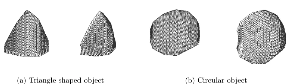
4.1 Sketches of 3D objects constructed with convex polygon inputs . . 38
4.2 Different wireframe examples of 3D objects constructed with rect-angular convex polygon inputs . . . 38
4.3 Different wireframe examples of 3D objects constructed with con-vex polygon inputs . . . 38
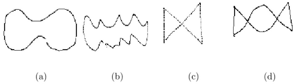
4.4 Sketches of 3D objects constructed with concave polygon inputs . 39 4.5 Different wireframe examples of 3D objects constructed with con-cave polygon inputs . . . 39
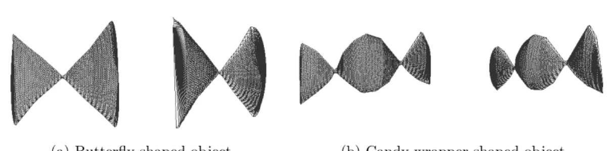
4.6 Different wireframe examples of 3D objects constructed with com-plex polygon inputs . . . 40
4.7 Resampling examples for different values of Input Point Resam-pling Constant (IRC). IRC is selected 20 for the input on the left and IRC is 10 for the input on the right. . . 40
4.8 Sketches of 3D objects constructed for SLS Testing . . . 41
4.9 Wireframe examples of 3D objects with different SLS values . . . 41
4.10 Dress sketch . . . 42
4.11 Wireframe model of a dress created with our system . . . 42
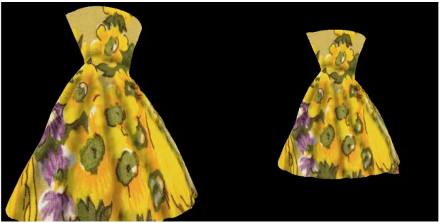
4.12 Textured model of a dress created with our system . . . 43
4.13 Almond sketch . . . 43
4.14 Wireframe model of an almond created with our system . . . 44
4.15 Textured model of an almond created with our system . . . 44
4.16 Fish sketch . . . 45
4.18 Textured model of a fish created with our system . . . 46
4.19 Leaf sketch . . . 47
4.20 Wireframe model of a leaf created with our system . . . 47
4.21 Textured model of a leaf created with our system . . . 48
4.22 Wall sketch . . . 48
4.23 Wireframe model of a wall created with our system . . . 49
4.24 Textured model of a wall created with our system . . . 49
4.25 Textured model of a wall created with ZBrush. (b) is the smoothed version of (a) . . . 50
Introduction
3D object modeling is a major research area in the computer graphics. As the powerful commercial modeling tools such as Maya [52] and 3D Studio Max [53] has been available to everyone and the power of the computer aided design tools have been discovered, many design related professionals such as engineers and architects utilize 3D modeling tools. The 3D modeling is also very popular (as expected) in its inevitable usage in gaming and 3D animation film industry. Most of the commercial and powerful 3D design tools today employ window, icon, menu, pointer (WIMP) interface [13]. This kind of interaction proved to be useful, and 3D modeling tools that employ such an interaction method are able to construct very detailed and realistic 3D models.
The 3D design tools that utilize the WIMP interface are very powerful but creation of 3D meshes with these systems require tedious work and much experi-ence. In order to remedy this, researchers have proposed a different interface, one that comes most natural to artists and designers, a sketch based interface. The idea that leads researchers to employ such an interface is that the traditional way to design and express ideas is done through sketching and one might extract ideas and understand the mental process under the sketch. Extending this idea to 3D modeling interfaces, researchers aimed to reconstruct 3D models by mimicking the cognitive process of human visual recognition system and by trying to under-stand the clues about the designer’s mental process that the designer provides to
the system when designing an object by sketching it.
The ultimate goal of sketch based modeling interfaces is briefly to provide an easy and intuitive modeling method that uses sketch input and to provide an interface that is as powerful as the WIMP interfaces. This goal is far from becoming true due to the complex nature of the 3D shape recognition process, however. This complexity arises mostly because of the lack of the depth infor-mation in sketches and in most of the interfaces that allow the user to provide sketch input to the computer.
Research in sketch based modeling interfaces today consists of systems that are scattered among different approaches to the sketch interpretation problem. Many different approaches have been proposed and none of these approaches proved nor aimed to be a final and complete method for sketch based modeling systems, which is only normal since the field is relatively new. The results of research are promising, however. Many incomplete but useful methods that pro-vide satisfactory results have been proposed. The current state of the research seems to become a collection of methods that employ different approaches that are able to address specific problems that sketch based modeling interfaces try to solve.
Observing the current state of the research, we try to address such a specific problem that has not been completely solved. The modeling of 3D objects is a problem of not only describing the overall structure of the object, but also a problem of depicting the detailed surface structure of the object. This is required in some systems more than others, especially in applications where the details are important such as modeling of 3D characters and objects in gaming and 3D animation film industry. The details of an object are especially important when modeling objects with perturbed free-form surfaces such as an almond or fish. These kind of objects have patterned or randomly placed perturbations on their surfaces.
Some of the current sketch based systems provide functionalities that allow such perturbations to be applied to the surface of an object such as Mudbox and ZBrush [54] [51]. These systems employ a depth painting method, which
allows the user to paint depth values on vertices using a brush. Some systems proposed to use shaded images [9] to construct shape of an object or to employ 2D painting interfaces to deform or manually correct mistakes on a pre existing 3D mesh [8]. The approach that is used in such systems inspired us to use shading data provided by the user to serve our purpose. Since these image based techniques are inadequate for fully 3D object creation purposes, we propose using such a technique as a modifier to a 3D object that is created by a purely sketch based 3D object creation method.
The main idea behind our work is that the perturbations and free-form struc-ture of a surface can be easily described by sketch input, with a traditional method named shading which is used for describing the depth values of a surface. We have observed that an artist provides shading input to depict the depth values of a surface, and this input can prove to be most valuable when reconstructing the surface of an object. We combine this idea with a 3D free-form object cre-ation approach that only requires 2D silhouette informcre-ation provided by the user. Our 3D object creation method uses sweep lines to construct surfaces which are similar to the rotational sweep surfaces used in Cherlin et al.’s work [3] which is explained in more detail in Chapter 2. The 3D object creation method employed in our system, when combined with a depth modification system, provides an intuitive and simple interface based solely on 2D sketch input.
The contributions of the thesis are summarized as follows:
1. We present a novel approach for creating fully 3D objects with free-form surfaces by only utilizing sketch input. We combine a 3D mesh creation sys-tem that is similar to the the rotational sweep surface technique proposed by Cherlin et al. [3] and combine it with a image based depth modifica-tion technique. This combinamodifica-tion provides an object with desired geomet-ric perturbations applied to its surface. The overall shape of the object is determined by the object creation technique and the surface geometry is determined by the height field that our image based system constructs according to the shading input.
2. We test regular triangular mesh structure for our image based technique. We use a regular triangular mesh to represent the geometry of the objects. The triangles of our mesh have a predefined edge length and are formed to fit inside vertices that are distributed uniformly through the area inside the borders of the mesh. In order to apply the appropriate perturbation value to a vertex in the mesh, we simply find the appropriate height value from the height map. When we calculate the perturbation value, we also add height values of adjacent elements in the height map which is constructed using user’s shading input. Then we apply the perturbation value to that vertex. When all vertices are perturbed in this manner, we obtain the desired surface geometry on the 3D final mesh.
We have observed that the usage of our system is easy and intuitive and users are able to model simple meshes with randomly placed or patterned perturbations with it. The limited scope of objects that can be modeled with our 3D object creation algorithm is a limitation, however. Also, the image based method we employ creates a fidelity problem when a curve is to be drawn on a 3D object such as the curves of a basketball. Thus our system is suitable for fast creation of 3D objects with detailed free-form surfaces.
The organization of the thesis is as follows: In Chapter 2 we briefly explain several different methods that discuss solutions to mesh creation problem and provide the background of the subject. Then in Chapter 3, we divide our system into sub-systems and explain each one in detail. In Chapter 4, we discuss differ-ent aspects and show results to the reader and finally in Chapter 5 we presdiffer-ent conclusion for our work.
Background and Related Work
There has been a lot of research in sketch based modeling systems. In this chap-ter, we explore different attempts that have been made in this research area. Most of the sketch based modeling systems include different sketch input acqui-sition methods [13]. Therefore, sketch input acquiacqui-sition techniques is explained in Section 2.1. In the rest of the chapter, we explain different sketch based mod-eling methods. We used in this chapter a division that is proposed by Cook et al. [14]. The research and different sketch-based modeling techniques are divided into 7 different parts and explained in the rest of this chapter in the following order: Gesture Created Primitives, Reconstruction, Height Fields and Shape-from-shading, Deformation and Sculpture, Blobby Inflation, Contour Curves and Drawing Surfaces and Stroke Based Constructions.
2.1
Sketch Input
One of the several concerns of sketch based modeling interfaces is sketch acqui-sition. Since user interaction is a fundamental issue for sketch based systems and many contemporary systems aim for easier user interaction, there is a lot of research in this area. There are several problems faced when user interacts with the system, and so there have been several different approaches to each of these
problems.
A major aspect about user input is the sketch acquisition device that users utilize to interact with the system. Several hardware choices are available, start-ing with the mouse and extendstart-ing all the way to more recently proposed devices such as haptic devices [41]. Among all the computer interaction devices, espe-cially those that are used in sketch based systems, one of the most ubiquitous devices is the mouse. Although the mouse is a familiar device for many users, it is hard for most users to successfully draw accurate shapes with the mouse. Tablet devices provide easier interaction to which most artists are used to, due to its similarity with the traditional pen and paper sketching. Some tablet devices employ the pressure data and orientation of the pen to amplify the expressiveness of the interaction device. There have also been different solutions to this problem, such as virtual reality devices or haptic devices [42] [41].
Another concern is sampling of the input data. In most cases when the user input is received, it is sampled. Since the real input provided by the user is continuous and sketch based systems receive the input in a discrete manner, the sampling process can be problematic. One problem this restriction creates is that the spatial distance between the consecutive sampled input points provided by the user varies. Users tend to draw some part of the sketch faster than others. This causes the faster drawn parts to have adjacent input points with larger spacing between them.
The sampled input is sometimes stored in structures called strokes. A stroke is defined as a sequence of sampled point input that the user provides to the system. A stroke starts with the user putting down his pen and ends when the pen is up. All points sampled between these two actions are used to construct the stroke.
Some of the contemporary systems use image based inputs. This approach is mostly used in systems that utilize image based approaches such as shape from shading (SFS) [8] [9].
results. Contemporary sketch based systems resample the input data for the sake of constructing the proper input desired by the user. There are several approaches to this problem.
One of the approaches proposed to solve the problem mentioned above is the minimax method [11]. This method minimizes the maximum distance between the approximating line and the points that represent the polygonal curve. Saykol et al. use another approach to approximate polygons [12]. In their work, they take polygon points as input and find importance level of these points, importance being determined by vertex velocity and acceleration, where vertex velocity is the rate of change of distance per angle and vertex acceleration is the rate of change of velocity per angle. Then using these vertex velocity and acceleration values, vertices with the highest importance level are found and used in the resulting polygon.
There are other approaches to this problem which produces rough approxi-mations. For example, Igarashi et al. proposed a simpler solution in their system Teddy [1]. In Teddy, the first and the last input point provided by the user is connected, and the result is checked. If the resulting shape is a 2D closed polygon, the system resamples the input points so that the adjacent points are equidistant. This approach aims the resampled points to form vertices of a 2D polygon that has edges with equal length, but it does not guarantee the result to be precise approximation.
Fitting the input provided by the user to other forms such as curves or lines has been employed by many researchers in their work. Some systems benefit from line or curve fitting techniques since lines or curves are simpler to analyse in some cases. There are also systems that use curves or lines to construct the object to be modelled.
There are several systems that use curve fitting to input strokes. For example in their work, Kara et al. use curve fitting to construct B-splines using a least squares curve fitting algorithm [7]. These curves are used in the model creation process where the user draws a wireframe model of the intended object. There are also other approaches to this problem. For example, Eggli et al. used least
squares curve fitting algorithms to construct B-splines [4] and Cherlin et al. used a reverse Chaikin subdivision technique to construct B-spline curves [3].
Some methods use both linear and curve representations. Such a work is pro-posed by Sezgin et al [10]. In their work, they propose a system that distinguishes line segments from curves from a drawing. The system finds straight line seg-ments in the stroke and then it discretely approximates Bezier curves from the curvy portions of the drawing. The resulting image consists of curves and line segments.
Line and curve fitting is mostly used in applications where details and preci-sion is most important such as engineering design systems. On the other hand, free form sketches have gained increased attention in the past decades. These differ from engineering design applications in that they provide more freedom to the user but lack the precision the engineering design applications offer. It is generally observed that people tend to draw several strokes before they get the final shape of the sketched object [14]. These lines depict the shape of the drawn object together. Pointing this issue, a sketching technique allows the user to draw many lines to describe the overall shape of an object and then use all of them to get a final result. This method of interaction is generally known as oversketching [14].
A number of systems use the idea of oversketching to allow the user to edit a line created before. For example, Fleisch et al. have proposed a system where the user draws an editing curve and the previously drawn curve is modified according to this curve [6]. Additionally they allow the user to provide several parameters. One parameter defines the effect of the overdrawn curve. The user is able to select how much the replacement curve will affect the original one. This parameter allows the user to completely change the original curve into the editing curve when it is 1, not to change it at all when it is 0. Thus, any value between 0 and 1 produces a curve between the original and the editing curve. In order to avoid breaks where the editing starts and ends on the original curve, the system smooths the curve around the starting and ending areas in order to make the transition. This transition interval size is also changeable by the user, where the
number of points is the parameter provided by the user.
Several approaches use techniques to find one curve that depicts the shape of the oversketched curve drawn by the user. One such system is proposed by Pusch et al. where the overall sketch is subdivided into boxes [5]. The subdivision ends when all boxes contain strokes that has roughly the same direction. These boxes are ordered so that internal strokes compose a complete curve. Then the points are fitted to a B-spline curve with the utilization of the ordering found using a reverse Chaikin subdivision technique.
Another method that uses oversketching input to form curves is proposed by Henzen et al. [2]. In their work, they proposed a system where the user is able to overdraw a line and the lines begin to fade in time. The final shape of the curve is formed by taking into account the most intensely coloured part of the overdrawn curves. This system allows the user to draw many lines and the final curve is constructed according to the part which is more saturated.
2.2
Sketch based Modeling Methods
After the the sketch input acquisition and re sampling is done, the next step is to interpret the sketch input and create 3D models.
2.2.1
Primitives Created using Gestures
An early approach to sketch based modeling was the creation of simple objects such as cubes or cylinders using gestures. The motivation behind some of these systems was to create complex objects by combining or applying other boolean operations with several simple objects. Several methods were proposed to create an unambiguous interface that allows the user to easily create simple objects with gestures.
was proposed by Zeleznik et al. [15] In SKETCH, users are able to draw several lines that combine into gestures. These gestures are recognized by the system and the recognized 3D object is created. For example, drawing an edge and two lines that are perpendicular to the edge and that end at any point on the drawn edge results in a 3D cuboid object and lengths of its sides are determined by the lengths of the drawn lines. There are also other objects that are not defined by their edges. An object of revolution, for example, can be created by drawing its profile and axis. There are several objects that can be created by SKETCH system, which are: cones, cylinders, spheres, objects of revolution, prisms, extrusions, ducts and superquadrics.
A similar system that uses gestural recognition is CIGRO which is proposed by Contero et al. [43]. CIGRO is capable of creating 3D objects using a small instruction set which includes gestures like adding/removing an edge, adding auxiliary edges and gestural commands such as move copy and delete. In CIGRO, user first draws a number of auxiliary lines that depicts the overall shape of the object. Then the user draws the real edges of the 3D object within the auxiliary lines. The real lines are differentiated with the auxiliary lines with the pressure information retrieved by the tablet device. The recognizer used in CIGRO is able to recognize elemental geometric forms such as triangles, rectangles, circles and ellipses.
Although SKETCH and SKETCH like systems shows that objects can be cre-ated using gestures with ease, the scope of such systems is very limited. Although more gestures can be added to overcome this, recognition of gestures gets harder as gesture library gets larger. Several researchers have designed suggestive sys-tems. The key idea of these systems is to inform the user of the possible results and allow him to select one, eliminating the ambiguity of the interpretation of the drawn shape. Such systems called GIDES and GIDES++, have been designed by Pereira et al. [16] [17]. In these systems, the user draws gestures and when the reconstruction process is complete, the system interactively suggests several options in a small window. When the suggestions (called expectation lists by author) are viewed, the user may or may not choose one. In the latter option, the user continues drawing in order to create a different and maybe a more complex
object. In these systems, the users are also able to apply editing operations using gestures, which also has suggestive feedback to the user.
Although these systems prove successful creation of some objects, their scope is limited even with the utilization of expectation lists. Moreover, a gesture based system restricts the user by forcing their input to predefined shapes and does not provide the freedom and expressiveness of traditional sketching.
2.2.2
Reconstruction
There are a number of studies that aim to interpret the users’ intention without using gestures. These systems evolved in order to remedy the limited scope and indirect interaction style of gesture based systems and to build systems that do not interrupt the sketching experience of the user. These systems also have to deal with the ambiguity of the 2D sketches.
Early researchers have tried to solve the ambiguity problem by identifying lines. Identifying a line here means differentiating lines so that when a 3D object is formed, the effect of the line is determined. This may be a tedious or even impossible job if the scope of objects that the system tries to identify is large. There are some methods that are used to differentiate (or label) lines this way.A number of solutions use a method called Huffman-Clowes line labelling [18] [19]. The key point in Huffman-Clowes line labelling system is that the scope of the system is limited to trihedral planar objects. The system labels every line in the 2D object. There are three different labels. Each line, being an edge of the 3D object to be created are either a convex, concave or occlusion edge. These labels mean that when the 3D object is constructed, from the viewers perspective, convex edges will be closer to the screen than its adjacent edges and concave edges will be farther away. Occlusion edges are edges that form the silhouette of the 3D object from the user’s perspective.
One system that uses Huffman-Clowes line labelling is proposed by Grimstead and Martin. [20] In their system, an incremental line labeller finds possible line
labellings that can be produced as the user draws. If the result is not what it is intended to be, then results derived from alternative labellings are shown. Then the system produces the 3D object with the selected line labelling by producing both visible and hidden faces from the labelled edges. Although this approach is capable of producing 3D objects and deal with the ambiguity, the system is very complex and its scope is limited to trihedral objects. The intervention of the user is also still required to resolve the ambiguity of the sketch.
In their system, Stilson et al. [21] have proposed a system that reconstructs a 3D object from line drawings that are drawn onto a 3D model. The motivation behind this system is to provide a system for architectural design by combining 2D sketching and 3D environments. The perspective information and pre-existing geometry of the 3D environment is used to interpret the 2D line drawings.
Another approach for reconstruction systems is proposed by Lipson et al. [22]. The main motivation behind their work is to emulate the human interpretation of 2D sketches. They claim that humans’ interpretation of 2D objects is based on their visual experience. Building a system based on this claim, they have tried to emulate the 2D-3D correlation by employing the correspondence information between 3D objects and their 2D projections. Using this information, they pro-duce a probability function for the candidate 3D objects that is later used to find a resulting 3D object. As the system produces correct 3D objects, the results are mostly rough objects as Lipson et al. indicates, which makes the system unusable for applications that require precision.
A different reconstruction approach is proposed by Piquer et al. which recon-structs 3D polyhedral objects using their symmetric properties [45]. To create an object, the user draws a 3D polyhedral object from straight lines. Then the system fins a symmetry plane from the sketch and creates a new coordinate sys-tem that the authors call the symmetry syssys-tem according to the symmetry plane found previously. Using the symmetry axis, the symmetry conditions are found and the 3D object is formed according to these conditions.
Since sketching systems based on reconstruction are suitable for engineering design and some objects that are constructed for engineering purposes may need
analysis of their physical properties, a system that incorporates these two features would be practical. With this motivation, Masry et al. developed a system that incorporates reconstruction based systems with analysers that provides analysis of the structural properties of the created objects [44]. Their approach has two parts: The first part is the reconstruction. The system allows reconstruction of an object that is composed of straight lines and planar curves. The second part is the analysis. In order to analyse the physical properties of the object created, the authors use finite element analysis technique.
One recent work, that reconstructs shapes from 2D silhouettes is proposed by Rivers et al [48]. In their work, the authors proposed a system where the user draws 2D silhouettes of a 3D object from top, side and front views. The system automatically constructs 3D shape of an object whenever the user draws different silhouette sketches of an object interactively. For example if the user draws triangles for the front and side views and a square for the top view, the system generates a 3D pyramid object. The creation of the models is achieved by boolean operations that are applied on the silhouette cylinders of the 2D sketches where the silhouette cylinder is defined by the infinite extension of a silhouette in the view direction. The resulting object is defined by the intersection of these silhouette cylinders.
2.2.3
Height Fields and SFS
One key feature of traditional pen and paper sketching is shading. Artists use the shading information to describe the shape of the object they are drawing. A number of researchers have proposed methods that utilize the shading information provided by the user to extract depth information.
Rushmeier et al. have proposed a system where users can edit the 3D geometry of an object by modifying images rendered from the 3D object with a 2D paint program or by using images from a photo or another model [8]. Using their system, the user is able to edit the surface of a 3D object by manipulating an image of the object with 2D paint operations such as cut, paste, paint, sharpen
and blur. Then the user is asked to edit the diffuse reflectance map in order to finalize the editing operation. The system also provides a solution for making major changes to a 3D model. In this editing scheme, the user provides an image of another 3D model or a real photograph and fits the image to the area to be edited. The grayscale changes are applied to the mesh after the grayscale image is inputted to a shape-from-shading algorithm. Then the resulting depth map is applied to the 3D object.
Another approach that uses shading to extract depth information is proposed by Kerautret et al. [9]. The authors mention that the current shape from shading approaches are not robust and are not able to provide a unique solution. In order to remedy this, they use several shaded images of the same object each provided by the user to construct a unique interpretation of the input. The images provided by the user contain the contour of the drawn object as well as the shading of the object under different lighting conditions. Although this system provides an intuitive method for creation of objects, the resulting objects are 212D, which means their depth extends in one direction.
The methods based on solely height fields and shape-from-shading provide intuitive model creation and modification but creation of fully 3D, complex ob-jects from scratch is still not possible with these methods. A commercial product named ZBrush allows creation of fully 3D detailed objects, by using a depth painting interface incorporated with modeling methods [51]. Using ZBrush, the users can interactively alter the surface geometry of an object by painting the surface of an object. The results of the ZBrush shows that incorporating the depth information with another technique provides better results.
2.2.4
Deformation and Sculpture
A number of studies utilize a more general form of editing in the sense that the whole object or a part of it is deformed in a more direct manner. In these systems, rather than using images to edit objects, the user deforms the object directly.
Most of these deformation techniques use interfaces that allow the user to sculpt or carve minor details onto the surface of an object. One such system pro-posed by Frisken et al. [34] utilizes Adaptively Sampled Distance Fields (ADFs) to allow local deformations. Their implementation of ADF provides a represen-tation for volumetric data and allows carving fine details. A distance field is basically a scalar field that specifies the minimum distance to a shape. The moti-vation behind the employment of such a representation is that the storage method is adaptive and sampling of the distance field is less where the local detail is low. The system allows fine carving of the object with efficient sampling rates since the method is adaptive. The user carves an object by moving the carving tool on the object’s surface.
Other surface representations are used for the deformation of the objects. For example, Bærentzen et al. proposed using the level set method for such purposes [35]. Using the level set method, the authors aimed to provide a generic technique for volumetric deformation. The level set method is briefly used to compute the evolution of surfaces that may expand or contract [35]. In their system, authors provide sculpting operations such as addition or removing of volumes and smoothing.
There are other attempts that have used global deformations on the objects. Wyvill et al. have proposed a system where models are defined by skeletal im-plicit surfaces [33]. The authors propose a structure called Blob tree, which is a hierarchical structure that consists of models on which warping, blending and boolean operations can be applied. The users are able to apply boolean oper-ations globally to implicit surface models and the hierarchical structure allows arbitrary compositions of these deformed objects.
Some proposed different techniques for modeling systems using deformation. One such attempt was made by Lawrence et al. where the user is able to deform and model an object with painting on its surface [36]. The work aims to provide a direct modeling and deformation interface. To deform a surface, the user paints over the surface and the system interactively provides a volumetric addition on the surface that is painted. The system also allows the user to select different
paints, changing the effect of the deformation, where the surface is propagated towards the surface normals in one selection and in other the surface is propagated in a constant direction.
One other approach was proposed by Singh et al. which allows the user to employ a structure called wires in order to deform an object [37]. Their deformation technique is similar to armatures used by sculptures, where wires define the shape of the object. Their system briefly defines a number of wires on an object and allows the user to manipulate the wires in order to deform the object.
These deformation and sculpture techniques are mostly intuitive mostly be-cause of its resemblance to sculpture techniques used by artists, but most of these systems are not practical when it comes to create an object from scratch. These techniques are better used as a supporting tool for model creation techniques. One such approach is proposed by Draper et al. in their system Freddy [46]. The authors proposed utilization of gesture recognized free-form-deformations on objects that are created using the 3D object creation employed in Teddy [1]. To deform an object, the user provides the system with gestural inputs. Then the gesture is recognized and the FFD lattice is displaced according to the input. The user can bend, twist, stretch or squash an object with different gestures. Kho et al. also proposed a system where the user deforms the object using a few curves [47]. In their system, the user provides two curves in order to deform a 3D object. The user first draws a reference curve as it was the skeletal description of the part of the 3D object to be deformed. The curve is projected onto the 3D space and the surface to be deformed according to the curve is calculated. Then the user draws a second curve and the surfaces of the object that is previously associated with the reference curve are displaced according to the second curve. The final deformed object provides a result such that the two curves are the bone structure of the object and the object is bent according to it.
2.2.5
Blobby Inflation
While there is a lot of research on sketch based modeling systems which try to increase the user’s control over the resulting mesh, there are also some researchers that have proposed solutions for creation of smaller set of objects by decreasing the user’s control over the resulting object.
Igarashi et al. has proposed such a system named Teddy, where the user’s sketch input is taken and a final 3D object is created [1]. The 3D object cre-ation method used by Teddy is called inflcre-ation, and as its name indicates the 2D silhouette provided to the system produces a resulting object so that it seems like it has been inflated. In to create an object in Teddy, the user provides the system with 2D free form strokes, which the system interprets as the silhouette for a object and then the system constructs a 3D polygonal object based on the given data. From the 2D strokes, the system creates a closed planar polygon by connecting the start and end points of the stroke. Then the system creates a spine for the 2D polygon. Here, spine is defined as the structure that describes the skeleton of the mesh and every point in the spine is equidistant from the edges. The spine is created by finding the chordal axis of the 2D polygon [24]. In order to find the chordal axis, the system triangulates the 2D closed polygon using constrained delaunay triangulation. After the triangulation, midpoints of internal edges of the triangulated 2D polygon are connected to create the cordial axis. Then the cordial axis is pruned to construct the final shape of the spine. After the spine is created, the triangles of the 2D polygon are divided by the spine and resulting polygons are triangulated. Then the vertices of the spine are elevated proportional to their distance between the vertex and edges. After the spine is elevated, a 3D mesh that covers the elevated spine edges and the external edges is formed. The final shape of the 3D mesh is constructed so that they form a quarter ovals between spine vertices and external edge vertices.
The inflation method that is employed by Teddy has its benefits. Although Teddy provides little control to the user on the final shape and the system is only able to produce rotund objects, Teddy provides a well defined, intuitive and easy to use technique to create 3D meshes. Although this system has benefits,
its aim is to construct approximate objects without precise details and is unable to create complex meshes.
The idea of using 2D sketch silhouettes to from 3D rotund objects has been used by other researchers who have been inspired by the approach used in Teddy. Karpenko et al., for example, have proposed using variational implicit surfaces in their work [25]. The variational implicit surfaces are proposed by Turk and O’Brien [26]. In their system, they allow the user to draw the silhouette of an object and the system inflates the outline of the object drawn and a 3D object is created. They also support drawing of additional shapes which overlap with the previously inflated objects. The inflation algorithm produces 3D objects so that the shape varies according to the width of the 2D shape drawn by the user, meaning that thin shapes produce cylindrical objects whereas circular shapes produces fatter 3D shapes. They also support creation of hierarchical shapes. The hierarchy is constructed according to the overlapping regions of the 3D object that each drawn shape produces and the previously created objects.
Tai et al. have noted that the technique used by Karpenko et al. requires high computational cost and proposed a technique that constructs 3D rotund objects from 2D shapes using convolution surfaces [27]. Their method extracts the skeleton of the 2D shape and a rotund generic convolution surface is created for each skeletal line segment. Their skeleton finding algorithm aims to find an approximate medial axis which is defined as the locus of the center of maximal circles inside the 2D shape. The 3D mesh is obtained by convolving the skeleton. Schmidt et al. have proposed a free form modeling system that provides many features in order to create a fully capable free form modeling system [28]. There are several modeling operations that the system provides. The system provides blobby inflation from 2D shapes, sweep surfaces that are created with linear sweeps and surfaces of revolution, cutting, blending operations. The system also provides surface drawings to be applied to a created 3D object, where the strokes are used to modify the surface of the 3D object.
The skeletal structure that is employed by some of the systems that use blobby inflation can be used for other purposes as well. In their recent work, Yang et al.
proposed a system called Life-Sketch that constructs 3D models from 2D sketches and extracts its skeleton to be used for animation purposes [50]. The authors used Teddy’s method of inflation to create 3D objects from 2D silhouettes. Then a skeleton extraction algorithm finds the skeleton of the object using the chordal axis which is created as a middle step of Teddy’s inflation algorithm. When the skeleton is found, the user can animate the object by rotating the object’s bones around its skeletal joints using a keyboard.
Most of the systems that utilize blobby inflation techniques are powerful tools in the sense that they allow creating simple objects with ease. Blobby inflation techniques provide an intuitive way of 3D simple object creation. Furthermore, inflation methods achieved what most sketch based systems aimed, creating 3D object from 2D sketches directly. The shortcomings of these techniques are the limited scope of objects that these systems are capable of creating and the lack of fine details.
2.2.6
Contour Curves and Drawing Surfaces
Sketching activity mostly involves drawing of curves to depict the overall shape. Since the contour of the object depicts much about the object to be designed, some researchers proposed modeling methods that is based on drawing curves. Although, since drawing 2D curves on a 2D plane is not enough to describe 3D surfaces, some sketch based systems evolved to use 2D curves to construct 3D curves or to create 3D curves directly.
An early work that is proposed by Cohen et al. proposes a technique that allows the user to draw 3D curves using 2D sketches [38]. After drawing 2D curves, the user provides a second curve that the authors call the shadow curve. As its name indicates, the shadow curve is the projection of the initial curve on a plane. The depth information and the 3D structure of the final curve is extracted from the shadow curve.
methods of 3D object modeling. Grossman et al., for example, proposed a method that is inspired by a design method called ”tape drawing” [39]. Tape drawing technique is used in automobile industry, where the artist draws the concept sketches of a car to large, 1 to 1 scale black photographic tapes. The system also uses large displays to provide a similar environment. The user interacts with the system by drawing 2D profile curves and these curves are then used in creation of 3D models. The 2D profile curves, drawn by user are constructed on 2D planes. The view of the system is a cuboid that includes the 2D drawing planes. These planes are shown to the user within the cuboid that contains these 2D planes as parallel surfaces. This display method is employed in order to help the user understand the relation between the drawn 2D curves and the underlying 3D object.
Some approaches have used similar techniques that allow creation of 3D ob-jects with 2D curves with a suggestive interface. The work proposed by Tsang et al., for example, uses image guided sketching on 2D planes on a 3D environment [40]. In the system, the user draws curves on 2D planes that has 2D images of an object that is similar to the one which is being created. The user draws curves on these 2D planes, and the system guides the user by attracting the drawn curves to the curves in the image. Suggestions of pre-existing and user created shapes is also available when the system matches the user input with one that is held at a database of shapes. The user is able to draw on orthographic 2D planes from three different viewpoints: top, side and front. All the 2D planes and 2D curves drawn on these planes are shown within a 3D cuboid volume.
2.2.7
Stroke Based Constructions
There have been attempts to construct 3D objects from 2D strokes by fitting sur-faces to input curves. For example, Wesche and Seidel have proposed FreeDrawer, a system where the user is required to provide the system with several strokes that describe the object [29]. The user needs to provide the overall description of the object as a network of curves. The system works in a 3D environment in which the user is able to construct 3D shapes by drawing 2D/3D curves and
creating surfaces between closed loops of curves. The system is best used by users with drawing skills, as it is also noted by the authors [29]. Michalik et al. have proposed another system that allows modification of B-spline surfaces by drawing 3D curves on the surface [30]. In their work, to create a new 3D ob-ject, the user draws curves which are projected onto planes. Using these curves, B-spline surfaces are created using a constraint based approach. This system is powerful but has high computation cost and the run time increases rapidly with large examples, as its authors note [30].
Although curve sketching is a powerful design tool, the need for drawing skills and the complexity of the object creation make these systems hard to use especially for users without an artistic background. A number of approaches have constrained the scope of the objects by sacrificing the freedom of the user but increasing the intuitiveness and expressiveness of the method. Levet et al. have proposed such an object creation method that uses a similar approach to inflation employed in Teddy [31]. The system requires the silhouette of the object and a profile curve. The silhouette is used to inflate the shape with a method similar to Teddy but the shape of the object depends on a profile curve which is also proposed by the user. The system elevates the vertices of the 2D shape according to the profile curve provided by the user which is in contrast to Teddy where the system inflates the 2D shape according to a circular profile curve.
Another approach, proposed by Cherlin et al. aims users to design 3D objects with a few strokes [3]. Their approach is based on a method used in traditional pen and paper drawing, which the authors call the spiral method, in which the artist draws the silhouette of the shape and then draws spiral curves to describe the shape of the object. In the system, creation of the 3D objects is done in a similar manner: The user first draws the silhouette of the object using two or more strokes, which are called the constructive curves. Then the midpoints of these two constructive curves are used to form another curve, which is used as a center curve to construct the surface of the object. Finally, for all points of the center curve, a circle that has a center at the center curve and is passing through the two constructive curves is created to form the final shape of the object. A surface that is created by this method is called a rotational blending
surface. Using this method, the system offers an easy to use, intuitive method for creating 3D objects which requires users to use only a few strokes to depict the object they want to create. Another creation method used by the system proposed by Cherlin et al. is called the cross sectional blending surfaces. In this method, which is similar to the rotational blending surface method, the user again draws two constructive curves. Then he draws a curve between these two constructive curves. The resulting surface between the two constructive curves is generated by using this curve rather than a circle. This method allows users to create thin, non circular objects with an arbitrary cross section.
A recent work has been proposed by Stiver et al. [49] where the system uses a stroke based construction system that is similar to what is used by Cherlin et al. [3]. The authors proposed a method for cloud modeling, where the user models the general form of clouds by strokes. Then using rotational or cross sectional blending surface techniques, an initial mesh is created. Then the mesh is filled with volumetric particles. These particles provide a noisy look on the boundaries of the cloud and makes it seem like one.
Stroke based systems are powerful and provide easy and intuitive way of 3D object creation methods, where the user is able to express the shape of the object with simple curves. Whereas some of these systems can be used to construct complex objects in detail and provide freedom to the user, some can be used to construct simpler objects by limiting the scope. In both cases, since the strokes are used directly to form objects, these systems are very intuitive.
Most of the approaches explained in this chapter have both strong and weak aspects and by merging two different methods, better solutions can be produced. Our system combines two of the above mentioned approaches, to provide a solu-tion for a very specific problem. Our system is inspired by two different limita-tions that we observed in the contemporary sketch based modeling solulimita-tions. We observed that blobby inflation methods are capable of producing 3D free-form objects from simple 2D silhouettes but they are mostly incapable for addition of surface texture details. We also observed that the shape from shading methods are incapable of creating 3D objects from scratch but can be utilized to form
detailed surfaces. In our work, we combine these two approaches and create 3D objects with detailed free-form surfaces.
Method Description
3.1
Overall System Description
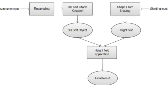
Our system takes two separate sketch inputs from the user. The first input is the silhouette, which is used in creating of the 3D object mesh; and the second input is the shading, which is used to create the height field. The two results are then combined by applying the height field on the 3D mesh to obtain the final result. The overall framework of the system is shown in Figure 3.1.
The system briefly operates in the following order: First, the user provides the system with a drawing of the 2D silhouette of the 3D object to be created. The silhouette input is resampled in order to create a smaller set of input points that carries roughly the same information. Then the 3D object creation step constructs a 3D object from the silhouette input. Then user provides the system with shading strokes that depicts the surface of the final 3D object. The user inputs the shading data by drawing strokes inside the 2D silhouette that was previously drawn. Therefore, the user sees every line and shading that is drawn as it were in pen and paper sketching. Then a height field is constructed using this shading data and finally the height field is applied to the 3D object to produce the final mesh. The overall procedure can be seen in Figure 3.2.
Figure 3.1: The Proposed Framework
3.2
System Description
This section aims to provide further explanation of the different parts of the sys-tem. In Section 3.2.1, storage and resampling of the silhouette input is discussed. The creation of the 3D object is explained in Section 3.2.2 in detail. In Section 3.2.3, creation of the height field is discussed and finally in Section 3.2.3, we describe the application of the height field on the 3D object.
3.2.1
Receiving and Resampling the Silhouette Input
Our system is compatible with 2D input devices. Using a 2D input device such as a mouse or a tablet device, a user without drawing skills is able to use our system to its full extent. When the user starts to draw the silhouette of the object, the input is sampled and is stored as dense points. The points are stored in a list structure. The list’s order is important; it is ordered according to the time the sampled point is received by the system. After the sampling of the silhouette input is finished, the input is resampled. The aim of the resampling is to find a rough estimate of the strokes provided by the user with fewer point samples, since
1. The user draws the silhouette of the object to be created 2. The 2D silhouette input is resampled
3. The 3D object is created
4. The user provides the shading strokes by drawing strokes inside the silhouette 5. A height field is constructed according to the shading input
6. The height field is applied to the mesh of the 3D object
Figure 3.2: Overall procedure
the future calculations will require edge intersection test between sweep lines and the planar input polygon (Section 3.2.2). We employ a resampling method that is similar to the technique that was used in Teddy [1]. The ordered list of sampled input points are held in P = {p0, p1, p2, ...., pn} where P denotes the list structure
and pi are the individual points where i = 0, 1, ..., n. The resampling algorithm
is given in Figure 3.3.
Input: P = {p1, p2, ..., pn}, input points
Output: R = {r1, r2, ..., rm}, resampled points
[1] R ← p1
[2] for pi, i = 1 to n − 1, do
[3] if distance(pi, pi+1) is bigger than or equal to IRC
[4] R ← R + pi+1
Figure 3.3: Input Resampling Algorithm
R stands for the list of resampled points and IRC is the Input Point Resam-pling Constant. After the resamResam-pling is over, a smaller number of input points is kept and the distances between adjacent points are close to IRC.
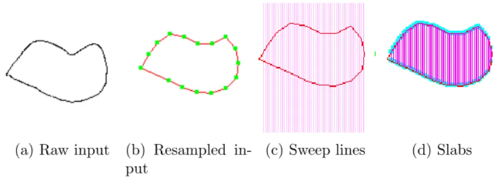
(a) Raw input (b) Resampled in-put
(c) Sweep lines (d) Slabs
Figure 3.4: Different steps of our 2D silhouette processing algorithm.
3.2.2
3D Object Creation
After the input is resampled, a 2D closed polygon that represents the resampled input is constructed. Once we have the 2D closed polygon, we aim to create the 3D object’s triangular mesh structure. During the triangulation, we elevate each of the vertices according to our vector elevation equation. The steps of this procedure can be seen in Figure 3.5.
1. Construct a 2D closed polygon from resampled points.
2. Determine whether the sweep lines should be parallel to x or y axis 3. Find the intersection points of each sweep line and edges of the polygon 4. Construct slabs by combining every two consecutive slab edge
6. Triangulate slabs to create the triangular mesh structure.
7. Elevate the resulting triangle points’ z value so that each slab edge becomes an arc.
Figure 3.5: 3D Object Creation Procedure
In order to form the edges of the 2D closed polygon, adjacent vertices of the resampled input points are connected. Since the resampled input points are
ordered according to the time they were received, by connecting each point with the next one we are able to create the closed 2D polygon. The edge creation algorithm is given in Figure 3.6.
Input: R = {r1, r2, ..., rm}, resampled input
Output: E = {(r1, r2), ..., (rm−1, rm), (rm, r1)}, polygon edges
[1] for ri, i = 1 to m, do
[2] if i is equal to m [3] E ← E+(ri, r1)
[4] else
[5] E ← E+(ri, ri+1)
Figure 3.6: Silhouette Edge Creation Algorithm
When the 2D polygon is formed by connecting the resampled vertices, we determine whether the sweep lines are parallel to the x or y axis. To achieve this, we first find the largest and the smallest x and y values among the input points. After these points are found, we calculate the distance between the largest and smallest x and y values. We will call these calculated values dmax,x and dmax,y
from now on. Then we compare the dmax,x and dmax,y. If dmax,x is bigger, we use
sweep lines that are parallel to y axis. If dmax,y is bigger, we use sweep lines that
are parallel to x axis.
After the sweep axis is selected, we generate sweep lines and for each sweep line we find the intersection points between the sweep lines and polygon edges. If the lines are selected to be parallel to the y axis, the first sweep line starts with the same x value with the point within the resampled input that has the smallest x value. If the sweep lines are selected to be parallel to x axis, it intersects the point with the smallest y value. The sweep lines are generated so that each consecutive sweep line has a predefined spacing in between. This predefined length is called Sweep Line Spacing (SLS ) . The equations of each sweep line are shown in the below equations:
is used if sweep lines are selected to be parallel to x axis,
x = xmin+ i × SLS (3.2)
is used if sweep lines are selected to be parallel to y axis.
In both equations SLS is the predefined measure that determines the resolu-tion of the mesh to be created since there will be no more subdivision between the sweep lines and i = 0, 1, ...., n where n makes the result of the equation equal to ymax or xmax. The next step is to find the intersection points between the
polygon edges and the sweep lines (Figure 3.4c) and to create slab edges which are formed by connecting the two intersection points that are found for each sweep line (Figure 3.4d). The complete line generation and intersection finding algorithm is given in Figure 3.7.
Input: E = {(r1, r2), ..., (rm−1, rm), (rm, r1)}, polygon edges
Output: S = {(s1, t1), (s2, t2), ..., (sk, tk)}, slab edges
[1] if sweep lines are parallel to the y axis [2] for y = ymin to ymax, increment y by SLS
[3] a ← 0
[4] for e starts with first element in E, until the last element of E [5] if y is between the y values of e
[6] t ← intersection point of e and the current sweep line [7] a ← a + 1
[8] if a is 1 [9] s ← t [10] else if a is 2 [11] S ← S+(s, t)
Figure 3.7: Sweep Line Generation and Intersection Finding Algorithm This algorithm gives us slab edges. Any two consecutive slab edges form a slab with a predefined length (SLS ) between them. Slabs are basically the polygons that are formed by connecting the two consecutive and parallel slab edges. They can be considered as thin plates that are constructed by dividing the polygon
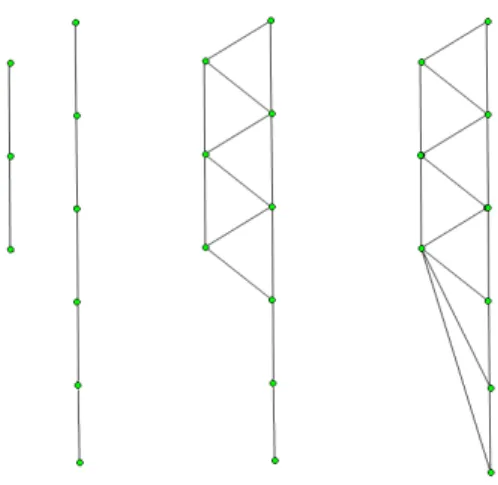
Figure 3.8: Slab Triangulation
with parallel lines, therefore when all slabs are considered, they form the polygon itself.
The rest of the 3D object creation process can be explained briefly with the following steps: When we have the slabs defined, we triangulate each slab. During the triangulation, we create points that are on the slab edges. When creating these points, an elevation offset for each point is calculated and applied to the point so that each slab forms an arc. The result of the triangulation with the elevated of vertices, is the triangular 3D object’s mesh.
The aim of the triangulation algorithm we employed is to construct triangles with one of their edges, which we will call base edge from now on, on one of the slab edges and one point on the other slab edge. Each triangles base edge’s length is determined by a predefined constant, Triangulation Edge Constant (TEC ). The triangles are formed so that they fill the whole area inside a slab. The triangulation process is shown in Figure 3.8. In order to triangulate the slab edges, we first find equidistant points for the two slab edges that form the slab to be triangulated. The point finding algorithm for a slab edge is shown in Figure 3.9.
z =ql2− ((x − m
Input: (s, t), a slab edge
Output: K = {(x1, y1, z1), (x2, y2, z2), ..., (xu, yu, zu), }, equidistant points found
[1] if s.x − t.x is 0 [2] dx ← 0 [3] dy ← TEC
[4] if s.y − t.y is equal to 0 [5] dx ← TEC [6] dy ← 0 [7] for x = t.x to s.x and y = s.y to t.y increment x by dx, increment y by dy [8] if x is bigger than s.x [9] x ← s.x
[10] if y is bigger than s.y [11] y ← s.y
[12] calculate corresponding z value according to Equation 3.3 [13] K ← (x, y, z)
[14] if x is equal to s.x and y is equal to s.y [15] break
Figure 3.9: Point Finding Algorithm
In Equation 3.3, l is the distance between the midpoint of the slab edge, x and y are x, y coordinates of the point and mx, myare midpoint’s x and y coordinates.
IC stands for inflation constant and is used to control the flatness of the object created. If IC is 0, then the object is a flat surface, if IC is 1 then the resulting object has circular cross sections. This equation is used in order to create semi elliptic lines from slab edges, when the vertices are elevated. The z values of vertices of the slabs are calculated according to this equation, so that when the slabs will be constructed, they are shaped as a thin plate that is bent so that it forms an arc. A graphical description that shows the 3D form of a slab after the triangulation of slab edges with the height values of its vertices calculated using Equation 3.3 is given in Figure 3.10.
After points to be used in triangulation are created from both slab edges, we find the slab edge with the minimum number of points between the two edges that
Figure 3.10: 3D Slab
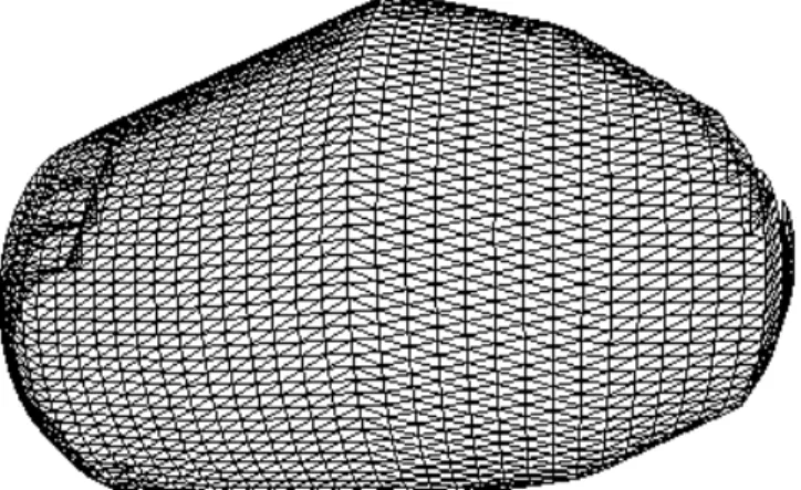
form the slab. When we determine the edge with the smaller number of points, we use the algorithm shown in Figure 3.12 to create the triangles as shown in Figure 3.8. Note that for simplicity, Figure 3.8 does not show the result of the elevation of vertices. Figure 3.11 shows a wireframe model of a 3D mesh generated by our algorithm.
As a result of this procedure, we finish triangulating the slabs. When all slabs are triangulated, we have the half of the triangular mesh representing the 3D object. To create the other half, we just create a mirror image of the first half of the mesh. For simplicity, we build our mesh on z = 0 plane, so that the mirror image of any vertex with coordinates x, y, z in the mesh is a point with coordinates x, y, -z.
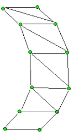
Figure 3.11: Wireframe 3D mesh
Input: A = {(x1, y1, z1), (x2, y2, z2), ..., (xi, yi, zi)}, finite point set
Input: B = {(`x1, `y1, `z1), (`x2, `y2, `z2), ..., (`xj, `yj, `zj)}, finite point set
Assume i < j [1] p1 ← B.f irst
[2] for p0 ← A.f irst to A.last
[3] if p1 is B.end
[3] break
[3] createTriangle(p0, p1, p1.next)
[4] if p0 is not A.last
[5] createTriangle(p0, p0.next, p1.next)
[6] p1 ← p1.next
[7] if p0 is A.last
[8] while p1 is not B.end
[9] createTriangle(p0, p1, p1.next)
[10] p1 ← p1.next
Figure 3.13: Brush sizes
3.2.3
Construction of the Heightfield
The shading strokes are stored as image pixels in order to make the transition of shading input to SFS input easier. Since the SFS input is image based, we use the shading data directly as an input to the SFS algorithm. We define a sketchpad, which is the area on the screen that user is able to draw onto. We get the input as it is drawn to the screen, meaning that whenever the pen of the tablet device touches the tablet or mouse’s first button is pressed, we get the pixel coordinate information of the cursor whenever the input event is received. If the stroke input is continuous, then each time the stroke is sampled, each sampled pixel coordinate information is received. We store the shading information in a 2D array, where each element corresponds to a pixel on the screen. When the corresponding pixel in the screen is drawn the corresponding element in the 2D array is set.
In order to provide an easier form of interaction, we provide different brush sizes for the user. As the brush size gets bigger, the pixels that are set are increased. The three different sizes for the brush are shown in Figure 3.13. As it can be seen in the figure, the brushes are designed so that they draw circular points.
Once the shading input is done, our system requires the user to inform the system that the shading is over. When user finishes shading and notifies the system, the image based shading data is used as input to the SFS step. We use Tsai et al.’s SFS algorithm [32] for this step. Since the input is already a 2D array of pixels, it can be utilized as an image. We input the image data directly into the SFS algorithm and obtain the result as a height field.
Tsai et al.’s SFS algorithm employs a linear approach, meaning to find a sur-face shape from shading, the authors linearly approximate the reflectance func-tion. In order to achieve this, the authors approximate the surface normal in a discrete manner. Then the authors linearize the reflectance function in depth. The overall procedure of Tsai et al.’s method is given in Figure 3.14. Refer to [32] for details of this algorithm.
1. The surface normal is approximated in a discrete manner.
2. Using these approximations with the reflectance function, the authors are able to linearly approximate a depth map using a Taylor series expansion for a fixed point.
3. Then for each point, the authors form a linear system.
4. Using the Jacobi iterative method, the linear system is solved.
Figure 3.14: Shape-from-shading method. Courtesy of Tsai et al. [32] As a result of this process, we obtain a height field that contains depth per-turbation values that are calculated from the shaded pixels. Since the user input is image based, each element in the height field contains depth information cor-responding to the pixel that has its indices as coordinates. In other words, we can obtain the depth perturbation value of a point in the 3D mesh by giving its x and y coordinates to the height field as indices and obtaining the corresponding depth value.
3.2.4
Application of the Heightfield on the 3D Mesh
After the 3D object mesh is constructed, as the next step, we apply the height field. Each element in the height field has values between 0 and 1, indicating the
height value to be applied. In order to apply the height values to the mesh ver-tices, we calculate a depth elevation value from the information we acquire from the height field. For each vertex, we first find the nearest 9 depth perturbation values from the height field. We use 9 values, one of them being the height value that corresponds to the vertex itself and 8 other height values that belongs to the adjacent elements in the height field. In order to get the depth perturbation values, we simply floor the x and y coordinates of the vertex and we employ the following equation to calculate the depth perturbation value where ∆z is the depth perturbation value of the vertex with coordinates x, y.
∆z = 1 X i=−1 1 X j=−1 heightF ield(x + i, y + j) 9 (3.4)