GENERATION OF FOCUSED SURFACE WAVES
WITH
A SOLID WEDGE
Abdullah ATALAR and Hayrettin
ItOYMEN i
Electrical and Electronics Engineering Department, Bilkent University
t
Electrical and Electronics Engineering Department, Middle East Technical Uiiiversity
Ankara, Turkey.
ABSTRACT
Focusing of surface acoustic waves on material surfaces was achieved by axicons in liquid immersion. The system consisted of a plane acoustic wave generator obliquely insonifying a cylindrical mirror placed per- pendicularly on the surface t o be examined. A similar axicon can be implemented with a solid cylindrical structure which does not require an immersion liquid. T h e lower cap of a solid cylinder is placed on the surface of the solid object, while the upper cap, where a shear wave transducer is placed, is inclined with respect t o the axis of the cylinder. Shear waves generated by the transducer are reflected from the free cylindrical surface of the solid. The reflected waves are incident on the bottom surface a t a critical angle and couple t o the object surface as surface waves to converge to a diffraction limited focus. T h e cylindrical solid material must be chosen from low shear wave velocity materials. The critical angle determines the inclination of the top surface and it is found from the solution of reflection problem for shear waves a t a solid- solid interface with aslippery boundary condition. T h e focusing system is implemented successfully with k i t e as the solid and aluminum as the object material.
1. INTRODUCTION
Use of focused surface acoustic waves (SAW) for imagingpurposes have been previously demonstrated [1,2]. The system consists of a parabolic cylindrical mirror surface insonified obliquely by a plane sound wave in a liquid medium. The reflected waves form a conical wavefront. If the conical wavefronts propagating in the liquid medium are incident a t a planar solid interface at the Rayleigh critical angle, all of the power in the conical wavefront will be transferred to a leaky SAW. The surface waves will focus to a diffraction limited spot before they completely leak back into the liquid medium. Any inhomogeneity at the focal point will cause a reflection of the surface waves, and the reflected SAW will find its way back t o the transducer which originally created them. Used in pulse echo mode, it is possible to build a n imaging system with this configuration [3]. Such an imaging system requires a liquid immersion medium.
Using the same principle, it is also possible to build a SAW focusing setup without an immersion liquid. Such a system will be essentially a solid wedge transducer [4,5] with a built-in focusing mechanism as explained below.
0090-5607187/oooO-0681 $1
.OO
0
1987 IEEE
2. FOCUSING SYSTEM
Fig. 1 illustrates the setup used. It consists of a solid cylindrical block
Transducer Electrical I
Focussed surface waves
Figure 1: Arrangement used to focus SAW at the object surface with an orthogonal planar surface on one end and with an angled pla- nar surface on the other end. A shear wave transducer is placed on the angled surface so t h a t the shear waves generated by the transducer insonify the cylindrical surface formed by the solid-air interface of the block. When a small portion of the circular cylindrical surface is uti- lized, it approximates well a parabolic cylindrical surface. No mode conversion a t reflection exists, because, typically, for this surface the incidence angle is above the critical angle for longitudinal wave excita- tion [6]. Fig. 2 shows the plots of the reflection coefficient a t a stress-free solid boundary for some solids. T h e critical angle is about 31.3 degrees for lucite and 20.5 degrees for lead. The reflected shear waves form a conical wavefront in the solid block as before
[a].
T h e axis of the gen- erated conical wavefront will lie a t a distance approximately half the cylinder radius from the reflecting surface. If the solid block is placed on a solid object surface to be examined, the conical wavefronts will impinge on the solid-solid interface formed by the solid block and the object. Typically, one would use a liquid couplant gel between the solid block and the object, in which case, the interface formed is a solid-solid interface with a slippery boundary. As we will show later, it is possible t o excite SAW a t the interface provided that the shear wave velocity in the solid block is less - preferably, by a factor of two or more - than the wave velocity on the interface. Moreover, the inclination of the up-I I I I I I I
I I I I I I - 211
0
6o (dcgrccrl
0 20 4 0
Figure 2: Reflection coefficient magnitude (solid curve) and phase (dashed curve) as a function of incidence angle for a stress-free lucite and lead boundaries
per surface of the block must be selected so t h a t , the shear waves are incident at the interface a t a particular angle in such a way to excite this wave. T h e polarization of shear waves must be vertical, because a horizontally polarized shear wave will not couple t o the object ma- terial through a slippery boundary. I t is appropriate t o choose a low shear velocity material for the block to keep the inclination of the up- per surface a t a practical value. Use of longitudinal waves. instead of shear waves, would have required a solid material whose longitudinal velocity is less than the wave velocity at the interface. This is a more stringent requirement to satisfy and such material combinations which give realizable incidence angles are hard to come by.
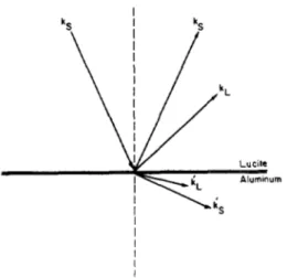
Excited SAW will converge to a diffraction limited spot, because the intersection of a conical surface with the planar object surface is always circular. If there is a reflector at the focal point, the waves will return through the same path to the shear wave transducer which originally generated them. When it is used in pulse-echo mode, it is possible to detect the return echo. Note t h a t , not all of the incident energy will be converging to the focal point, some of it will leak back into the solid block in the form of shear waves before it reaches the focus. Similarly, not all of the reflected SAW will be collected by the transducer, because some of the waves will keep propagating in the form of SAW. We have solved the shear-wave incidence acoustic reflection problem a t a solid-solid interface with a slippery boundary (See Fig. 3). Isotropic and nonpiezoelectric solids are assumed. The boundary conditions are the continuity of normal particle velocity and the normal traction force. T h e components of the traction force parallel t o the surface on both sides must be zero because of the slippery condition. From these four boundary conditions, it is possible to find an analytic solution for this problem and the reflection coefficient for shear waves can be written as
N R = - - l D with N
=
4 ( k g - k:)(k? - k:(ki - k:) Figure 3:cite-aluminum) interface with a slippery boundary
Geometry of the reflection problem a t a solid-solid (lu-
and
where 72 is the reflection coefficient of vertically polarized shear waves, subscripts
S
andL
refer t o shear and longitudinal waves, primed and unprimed variables refer t o the object and block medium, respectively.k's represent wavenurnbers, k, is the component of the wave vector along the interface and c's are elastic constants.
Lucite has a low shear velocity, 1287 m/sec [7], therefore it is appro- priate for most object materials. We have plotted the magnitude and phase of the reflection coefficient as a function of incidence angle i n Fig. 4 for lucite-aluminum interface. From the magnitude curve, three critical angles are apparent: For anglessmaller than
SL,
= sin-'(k;/ks) three refracted waves - a reflected longitudinal wave, transmitted lon- gitudinal and shear waves - will exist in addition t o the reflected shear wave. For angles exceeding 8LL no longitudinal waves in aluminum can exist. AboveS
:
,
= sin-'(k$/ks) the shear waves in the aluminum can no longer be excited, and finally beyond BCL = sin-'(kL/ks) a longitu- dinal wave reflection in the lucite can not occur. T h e phase transition a t O c ~ = 31° indicates that a wave a t interface is excited. This angle corresponds to a wave velocity of about 2500 m/sec a t the interface, considerably less than the SAW velocity on the free aluminum surface. It is seen that this wave is excited a t an angle slightly higher than O c ~ T h e velocity of this wave is primarily determined by the shear wave t o longitudinal velocity ratio in the lucite, not by the SAW velocity in the aluminum. This is a rather interesting wave excited when a vertically polarized shear wave is incident a t a slippery solid-solid interface. At this incidence angle, all the waves except the shear wave in the lucite are evanescent. Hence, the generated wave is a leaky wave much like the SAW excited on a liquid-solid interface.T h e Schoch Displacement, A s , can he related to the rate of change of
reflection coefficient phase with incidence angle [SI. This value can be readily determined from the analytical expression [9]:
3. EXPERIMENT
I
0 I
1
IO 14 18 2 2 26 30 34
Cagrcesl
Figure 4: Magnitude (a) and phase (b) of the reflection coefficient as
a function of incidence angle a t the lucite-aluminum (solid curve) and lead-aluminum (dashed curve) interfaces for the slippery boundary case
where
LR
indicates the phase of the reflection coefficient and O c ~ is the critical angle. A s is a factor which shows the rate of decay of SAW and it is important for optimization of focusing system efficiency. We have used Eq.1 and 2 t o calculate a number of cases. Table 1 summarizesthe results. For optimum efficiency, the radius of the cylinder block Material Pair
1
O c ~ (degrees)I
As/XsLucite-A1
1
31.46I
260 Lucite-Fe 31.30L u c i t e N i 31.31
Pb-A1 23.95
Pb-Fe 21.32
Table 1 : Critical angle and Schoch Displacement for a number of ma-
terial combinations
must be related to the Schoch Displacement by [2]
r = 1 1As. (3)
Fortunately, the function which relates r/As to efficiency of the system is not a fast varying function [2], hence non-optimal cases can be used without great losses.
Inspection of Fig. 4 indicates that there is a phase transition at an angle corresponding t o SAW velocity on the aluminum surface. However, the slope of the phase transition is positive, resulting in a negative Schoch Displacement! In this case, the evanescent SAW will exist as a backward traveling wave [lo], making it inappropriate for focusing in the forward direction.
We have built a SAW focusing block from lucite. An operating fre- quency of 1 MHz was chosen. At this frequency and aluminum as the object material, the optimum radius of block from Table 1 is 40 cm. Instead, we have used a block with a radius of 3 cm giving afocal length of 1 . 5 cm. This non-optimum but practical size of the block causes a
loss of 16 dB [2]. T h e inclination angle of the upper surface is to be 31.4 degrees. We have manufactured a number of focusing blocks with slightly varying angles to determine the optimum excitation angle. For proper insonification of the cylindrical surface a block height of 2.8 cm is chosen. Note that , the shear wave attenuation in lucite is quite high: 2.1 dB/cm a t 1 MHz as given in the literature
[ll].
T h e shear wave transducer was rectangular in shape and 1.1 cm by 2 cm in size. This transducer size with the above mentioned cylinder
block gives an f-number of 0.75. Due to low shear impedance of lu- cite, it is hard to excite shear waves in it by a high impedance PZT
transducer. Moreover, high impedance backing used for the transducer reduces coupling into the lucite. We had to add a quarter-wave match- ing layer between P Z T and lucite. T h e transducer is able to generate 3 microsecond shear wave pulses at 1 MHz.
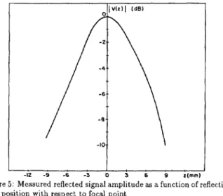
A straight edge discontinuity on the object surface is placed a t the expected focus position under the block. A signal is observed with the predicted time delay. The signal showed the characteristics of a focused wave as the position of the edge was varied with respect t o block. Fig. 5
shows the the measured signal amplitude as a function of position of
i I
-12 -9 -6 -3 0 3 6 9 z(rnrn1
Figure 5: Measured reflected signal amplitude as a function of reflecting edge position with respect to focal point
reflecting edge with respect to the focal point. To be able to calculate the conversion efficiency of the focusing wedge we have measured the signal reflected from a flat lucite block of the same path length with the same transducer. Comparison of this signal level with the signal from the focusing wedge gives a loss value of 16 dB. Comparing this value with the calculated value above shows us that the reflection coefficient of the interface wave a t the straight edge discontinuity is close to unity. Note t h a t, we have made no correction for diffraction losses.
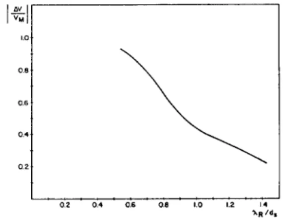
To show the focusing ability of the wedge, we placed a series of small holes drilled perpendicular to the surface a t the focal line. T h e mod- ulation depth of the return signal was measured as the focusing block was moved along the focal line. This experiment was repeated for a
number of different hole spacings t o produce different spatial frequen-
cies. Fig. 6 is a plot of the results. Experiments indicate that it is able
lmvll
I
I v M I 1.0 . 0 8 0.6 0.4. 0 2 0 2 O A 0.6 0.8 1.0 1.2 14 '*RFigure 6: Measured modulation transfer function for the focusing block t o separate holes of 1 m m diameter with a center-to-center spacing of
2 mm. A resolution of 2 m m with a surface wave wavelength of 2.5 m m
shows the diffraction limited character of the focused wave.
4. RESULTS AND CONCLUSIONS
Non-optimum size of the block causes a rather large loss; 16 dB. This decreases the reflected signal level considerably, but still the signal is easily measurable. An optimal size focusing wedge a t low M H z frequen-
cies is impractically large. At higher frequencies optimality condition can be met, but this time excessive absorption losses will emerge. One may also expect a high level of background signal due to multiple re- flections in the bounded geometry of block material. Nevertheless, this background level is significantly lower than the echo signal.
The estimated reflection coefficient of unity for the straight edge dis- continuity is not in agreement with a typical SAW reflection coefficient value. For the SAW, a typical reflection coefficient is around 0.4 [12] and it is mainly due to a high transmission coefficient of SAW propa- gating onto the edge surface. Whereas, for o u r case a higher reflection coefficient is expected. because the interface wave ceases t o propagate when the object surface loses contact with the wedge surface. At the onset of the project, we expected t o be able to excite a SAW on aluminum surface with a velocity very close to the that of the free aluminum surface. However, calculations indicated that only a wave, whose velocity is close to the longitudinal velocity in the lucite, could be excited. This wave has properties very similar to a leaky SAW, but it is a special wave in the sense that i t occurs only when two solids are brought together with a slippery bond. This wave velocity changes only very slightly for different object materials as long as the shear wave velocity of the object material is higher than the longitudinal wave velocity of the block material. If the difference of these two velocities are made smaller, the Schoch displacement decreases and consequently, the range of angles in which one can efficiently excite the surface wave will increase. Since the critical angle changes only very slightly, one can build a focusing wedge with a fixed inclination angle applicable to a number of different object materials. If required, a wedge with optimal and practical size may be constructed with proper combination of the block and object materials.
It is difficult t o adjust the excitation angle in a solid focusing block,
if the Schoch displacement is high. Also, achieving optimal cylinder radius may be difficult. New wedge materials will have to be tried.
For example, calculations indicate that lead would be a proper choice. Not only it is an easy t o match material for PZT, but also it results in a small value of Schoch displacement for most materials, hence giving a high efficiency. Lead yields a manageable optimal cylinder radius, which means that 16 dB loss of lucite wedge can be reduced to the theoretical 3 dB limit with a wedge made out of lead.
ACKNOWLEDGEMENT
This work was supported by TUBITAK Ankara Electronics R
8
DInstitute.
References
H.Koymen and A. Atalar, "Focusing surface waves with an axi- con", Appl. Phys. L e t t . , vol. 47, pp. 1266-1268, 1985.
A. Atalar and H. Koymen, "Use of a conical axicon as a surface acoustic wave focusing device", IEEE Trans. Ultrason. Ferro. and
Freq. C o n t . , vol. 34
,
pp. 53-63, 1987.H . Koymen, A. Atalar, T. Ciloglu. M. Onder, Cetin Uzel and H. Yavuz, "Imaging flaws close to surface using focused surface acoustic waves" in Proc. IEEE Ultrasonics Symposium, pp. 755- 7 5 8 , 1986.
B.L. Bertoni and T. Tamir, "Characteristics of wedge transducers for acoustic surface waves", IEEE P a n s Sonics Ultrason., vol. 22,
pp. 415-420, 1975.
H.L. Bertoni, "Coupling layers for efficient a e d g e transducers",
IEEE Trans. Sonzcs Ultrason., vol. 22, pp. 421-430, 1975.
[6] B. A. Auld, Acoustic Waves in Solrds, vol. 11, Academic Press, New York, 1973.
[7] V.M. Ristic, Principles of Acoustic Devices, John Wiley and Sons,
Kew York, 1983.
[8] L.M. Brekovskikh, W a v e s in Layered Media, academic Press, New
York, 1960.
[9] H.L. Bertoni and T. Tamir, "Unified theory of Rayleigh angle phenomena for acoustic beams a t liquid-solid interfaces", Appl.
Phys., ~ 0 1 . 2 , pp.157-172, 1973.
[lo] T. Tamir and H.L. Bertoni, "Lateral displacement ofoptical beams a t multilayered and periodic structures", J. O p t . Soc. A m . , vol. 6 1 , pp. 1397-1413, 1971.
[ l l ] B. Hartman and J . Jorzysinki, "Ultrasonic hysteresis absorption in polymers",
J.
.4ppl. Phys., vol. 43, pp. 4304-4312, 1972.[12] F.C. Cuozzo, E.L. Cambiaggio, J - P Damiano, and E. Rivier, "In- fluence of elastic properties on Rayleigh wave scattering by normal discontinuities," IEEE Trans. Sonzcs Ultrason., vol. 24. pp. 280-
289, 1977.