Contents lists available atScienceDirect
Engineering Failure Analysis
journal homepage:www.elsevier.com/locate/engfailanalEffects of induction motor end ring faults on motor performance.
Experimental results
Asım Gökhan Yetgin
⁎Mehmet Akif Ersoy University, Department of Electrical-Electronics Engineering, 15030, Burdur, TURKEY
A R T I C L E I N F O Keywords:
Induction motor Broken rotor bar failure End ring failure Experimental analysis Performance analysis
A B S T R A C T
Induction motors are inherently robust in construction, although faults can occur inside or outside in the motor due to various reasons. These failures cause deterioration of the motor performance and it can even cause the motor to be disabled. As a result of literature studies, it has been seen that a hole is opened in the middle part of the rotor bars for the induction motor rotor bar failures. In this study, different the studies in the literature, faults were introduced on the end ring part and on the intersections of the end ring and the rotor bars. The aim of this paper, end ring faults was investigated the effect of a squirrel cage induction motor on the motor perfor-mance. Seven motors with the same power and physical characteristics were used in the study. One of the motors is used as a reference (healthy) motor and the other six motors which have got with various faults in the end ring part. The three motors were used exactly as the faulty motor at the intersection of the end ring and the rotor bars, and the other three as the faulty motor which caused a scraped on the end ring part. No-load, locked-rotor and loaded operation tests were performed separately for each motor. The core losses, copper losses, current, power factor, ef-ficiency, torque-speed characteristic and etc. values were obtained for seven motors. The motors that are tested are squirrel cage, 3 phase and 4 kW power. The obtained results are presented in comparative tables and graphs. Core loss and copper losses have increased by 21.57% for 3 scrapped motor and 9.83% for 2 broken rotor bar motor respectively, compared to the healthy motor. The efficiency value is reduced by 3.4% for the 3 scraped motor.
1. Introduction
Induction motors play a very important role in industrial, commercial and domestic applications because they have a number of advantages over the other types of motors. It is the most preferred electric motor due to its robustness, simple structure, reliability, low cost, low maintenance requirement, stable operation, ease of control [1–5]. While studies continue to improve the performance of induction motors, these studies are mostly concerned with the development of material science and production techniques. Computer aided design methods are very useful in determining performance values before motors are produced. These design methods enable the creation of new designs and the inability to understand the performance degradation due to some faults [6]. Although induction motors have a solid structure, many faults can occur in the motor. Moradian and friends have proposed a method based on artificial neural networks to detect broken rotor bar and end ring faults which is occur in the induction motor rotor part [7]. In the Hayri and Osman's study, the effects of broken rotor bar failures on the torque-speed curve of the squirrel cage induction motor were investigated ex-perimentally [2]. Glowacz and friends propose early fault detection technique which uses method of selection of amplitudes of
https://doi.org/10.1016/j.engfailanal.2018.10.019
Received 19 June 2018; Received in revised form 2 October 2018; Accepted 22 October 2018 ⁎Corresponding author.
E-mail address:[email protected].
Available online 23 October 2018
1350-6307/ © 2018 Elsevier Ltd. All rights reserved.
frequencies and Linear Discriminant Analysis to classify feature vector [8]. In their work, Yahoui and Grellet presented a new technique that allows the diagnosis of an end ring fault in three-phase squirrel cage induction motor [9]. In the Takeo study, not only the broken rotor bars but also an induction motor has examined the diagnosis of broken end ring faults. The difference between the broken rotor bars and the broken end ring are experimentally clarified by Fourier analysis of the stator currents [10]. In the study of Tulicki et al., they analyzed the motors with a healthy, one broken rotor bar, two broken rotor bars and dynamic excisities using the Bispectral Analysis method. They obtained the stator current, vibration and acustic pressure values of the motors [11]. Arredondo et al. analyzed the changes in the induction motor for mechanical unbalance condition, bearing faults and broken rotor bars [12]. Glowacz et al. described an early fault diagnostic technique based on acoustic signals. The presented technique was used for a single-phase induction motor. They mea-sured and analysed following states of the motor: healthy single-phase induction motor, single-phase induction motor with faulty bearing, single-phase induction motor with faulty bearing and shorted coils of auxiliary winding. They stated that this method can be used for other types of rotary electric motors [13]. Prainetr and friends studied on a mechanical fault system using simulation and experimental detection of the eccentric fault in different levels of an induction motor. They analysed current signal and sound acoustic time-frequency domain with Fast Fourier applied to estimate fault harmonic signal, noise, caused by eccentricity [14]. Mesbeh and friends investigated the effects of current changes in rotor bars and end ring on induction motor operation of different error scenarios. They show that rotor faults greatly affect both the amplitude and the harmonic content of the currents in the rotor bars and end ring [15]. Mini and Ush-akumari investigated broken rotor bar failure of three-phase squirrel cage induction motor. They determined the amplitude of the stator current, speed, negative sequence of the current and change in line currents based on the FFT magnitudes [16]. The Glowacz described acoustic based fault diagnosis techniques of a three-phase induction motor. They analysed four real states of the three-phase induction motor: healthy motor, one broken rotor bar, 2 broken rotor bars and faulty ring of squirrel cage [17]. The objective of Merizalde and friends article is to conduct a macro or global analysis of the different methodologies applied to diagnose the failures that can occur in an induction motor in a timely manner and to avoid its exit from service in an unexpected way [18]. Magdaleno and friends proposed the use of the Empirical Mode Decomposition and Hilbert Spectrum to perform the current signature analysis for incipient broken rotor bars in induction motors. The novelty of the proposed methodology is the early detection of a partially broken rotor bar at a full and a half mechanical load [19]. The contribution of Guillen and et al., is to propose a new methodology for detecting and classifying broken rotor bar faults in induction motors. In the methodology, a new technique used Tooth-FFT is introduced for detecting time-frequency changing signals [20]. In Arabaci and Bilgin's work, they analyzed the effect of rotor failures on stator current using FFT. The analyzes were made for a high resistance rotor bar, a broken bar, two broken bars, three broken bars and an end ring broken. According to the obtained result, rotor failures have caused significant changes in the sidebands in the current spectrum [21]. Maraaba and friends paper presents the development of a neurak network-based diagnoistic tool for detecting the severity and exact percentage of stator inter-turn faults in three-phase induction motors. Simulation results illustrate the advantage of using a steady-state electromechanical torque signature as a fault indicator [22]. In their work, Spyropoulos and friends used finite element method analysis to examine the effects of broken rotor bar failure on the induction motor electromagnetic characteristics. They used one healthy motor and one broken rotor bar motor [23]. Xie et al. examined the induction motor with healthy and broken rotor bar depending on the thermal stress. It has been stated that broken rotor bar failures can have an effect on the thermal profile and thermal stress of the motor and that the breakpoint always occurs at the junction of the bars and end rings [24]. Singh and Naikan present a new method to diagnose half broken rotor bar fault in induction motor drive, running under various load conditions using a variable frequency drive. They proposed in the paper that uses Multiple Signal Classification algorithm on the square of the current signal, in order to detect the half broken rotor bar fault at various load conditions [25]. Glowacz and friends proposed a technique of fault diagnosis based on recognition of currents. The authors analyzed 4 states of three phase induction motor: healthy motor, one faulty rotor bar, two faulty rotor bars and faulty ring of squirrel cage. An analysis was carried out for original method of feature extraction called msaf-ratio15 [26].
In this study, different end ring failure of seven induction motors with the same power and characteristics were analyzed. One of these motors was used as a healthy motor (reference motor) and the other 6 was used as a faulty motor. Three of these motors were brought to the broken in the rotor bars. In the other three motors, only end ring failure was created. No-load, locked-rotor and loaded operation tests were performed for each motor. The performance values (efficiency, torque, current, power factor, speed, etc.) of the motors with healthy and end ring faults are compared.
2. Types of induction motor faults
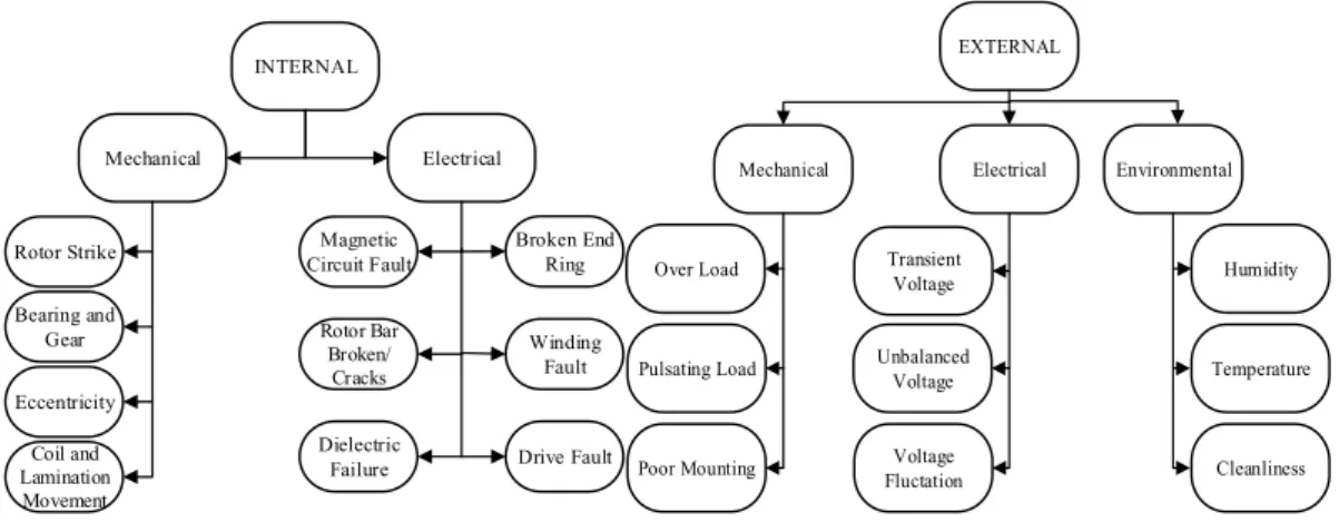
Although induction motors are robust and reliable, failures can occur, such as broken rotor bars, bearing failures, manufacturing faults, and end ring faults [5,27,28]. For example, faults can occur in the motor, such as short circuiting of cables, ground faults, bearing and gearbox defects, broken rotor bar, cracked end ring. Also, faults can occur outside of the motor such as phase error, the asymmetry of the power supply, mechanical overloading [27]. With the occurrence of faults, the induction motor starts to operate faulty and this motor failure can result in major revenue losses for the enterprise and increased motor maintenance costs. For this reason, early identification of failures is of great importance [1]. There are many methods to diagnose and observe faults in induction motors, which are explained in detail in [29–31]. Faults that can occur in squirrel cage induction motors can be grouped under two main headings which are external and internal [32]. These faults are then separated between themselves as electrical and mechanical faults [33]. The details of these failures are given inFig. 1[1,3,4,32,34].
Through the industrial experience several surveys of faults of electrical machines have been conducted. InTable 1, the results of the surveys of IEEE-IAS and ERPI are compared concerning induction machines.
Juneghani and friends, Spyropoulos and Mitronikas have shown that faults can occur in the induction motors can lead to un-balanced air-gap voltage and line currents, increased oscillations at the torque and speed, reduced average torque, increased losses,
reduced efficiency, and overheating [3,35]. 2.1. Rotor Bar and End Ring Faults
Despite its reliability and stability, faults occur in the induction motors. Certain of these faults are rotor failures. Rotor faults can occur as minor faults during production, or they can be caused by manufacturing errors on the rotor or by mechanical, environ-mental, electromagnetic, or thermal pressure on the motor. Even if these failures are initially small, the failures can grow even bigger over time due to the pressures. Especially transient events accelerate this growth. Faulty motors negatively affect torque, current and speed of the motor [2]. Broken rotor bars can quickly fail in large motors, especially with multiple poles. However, if there are enough broken rotor bars, the motor may not move because of it cannot generate sufficient starting torque. Discovery of broken rotor bars also leads to time-consuming and expensive repair costs [6]. In the induction machines, 20% of the failures occur in the rotor part and especially in the end ring of squirrel cage motors [9]. The connection region between the rotor bars and the end ring is a common source of mechanical failures in squirrel cage induction motors [36]. Reasons for failures of rotor bar and end ring are thermal, magnetic, residual, dynamic, environmental, mechanical stresses [4], electromagnetic forces, electromagnetic noise and vibration, centrifugal forces and fatigue parts [35].
Each rotor bar and segment of end-ring is substituted by an equivalent circuit representing the resistive and inductive nature of the cage. Such an equivalent circuit is shown inFig. 2(a) and for the broken end ring in the section of the kthrotor loop the corresponding loop current is zero as is presented inFig. 2(b) [5].
3. Studied motors and experimental setup
For the experimental study, 3-phase, 4 kW, 4-pole squirrel cage induction motors are used. Specifications and rated parameters of the studied induction motor are given inTable 2.
The views of the motors used in the experiments are given inFig. 3andFig. 4. The rotor image of 4 kW healthy motor is shown in Fig. 3.Fig. 4(a) is 1 broken rotor bar motor,Fig. 4(b) is 2 broken rotor bars motor,Fig. 4(c) is 3 broken rotor bars motor,Fig. 4(d) is 1 scraped motor,Fig. 4(e) is 2 scraped motor,Fig. 4(f) is 3 scraped motor.
The broken formed in the rotor bars have a depth of 8 mm and a width of 6 mm. For broken rotor bar faults, the location of the rotor end ring and rotor bar junction is selected. The scraped faults are only caused by the rotor end ring part.
The block diagram of the experimental set-up is shown inFig. 5. The motor test setup is given inFig. 6. In the experiments, auto-transformer is used for voltage adjustment, amperemeter and pens-amperemeter are used for current measurement, Fluke 23-B power analyzer is used for power measurement and fucolt brake is used for the loaded operation tests. No-load tests are conducted at nominal voltage of 400 V. The values of the locked-rotor tests were measured by subtracting them up to the rated current value of 8.1 A (In= Ik). For the loaded operation test, it was carried out at nominal voltage and at the nominal speed of 1440 rpm. The frequency is 50 Hz. In addition, the current THD values and harmonic variations is obtained from the power analyzer.
INTERNAL Mechanical Electrical Rotor Strike Bearing and Gear Eccentricity Coil and Lamination Movement Magnetic Circuit Fault Rotor Bar Broken/ Cracks Dielectric Failure Broken End Ring Winding Fault Drive Fault EXTERNAL Mechanical Electrical Over Load Pulsating Load Poor Mounting Transient Voltage Unbalanced Voltage Voltage Fluctation Environmental Humidity Temperature Cleanliness
Fig. 1. Block diagram presentation of internal and external faults. Table 1
Comparison of IEEE-IAS and ERPI [3].
Major components IEEE-IAS % of failures ERPI % of failure
Bearing Related 44 41
Stator Related 26 36
Rotor Related 08 09
4. Results and Discussion 4.1. No-load Test Results
The no-load test was carried out the nominal voltage at 400 V. No-load operating currents (I0) for the motors are given inFig. 7. The no-load operating current of a healthy motor is measured as 4.20 A. It is seen that the no-load current increases but a horizontal
Fig. 2. a) Rotor cage equivalent circuit showing rotor loop currents and circulating end ring current b) broken end ring. Table 2
Nameplate specifications and parameters of the studied induction motor.
Motor parameters Values
Rated voltage (V) 400
Rated current (A) 8.1
Frequency (Hz) 50
Rated power factor 0.82
Nominal torque (N.m) 26.5
Winding connection Delta
Number of stator slot 36
Number of rotor slot 28
Rotor speed (rpm) 1440
Operating mode S1
End ring depth (mm) 9
End ring width (mm) 20
increase occurs for broken rotor bar motors. For the scraped motors, this increase appears to be vertical. The largest no-load current value (4.86 A) was obtained from the 3 scraped motor. No-load power factor values varied in the 0.21–0.22 band. The number of no-load speed varied between 1498 and 1499 rpm. The change in core loss (P0) values is given inFig. 8. The variation of core losses shows a similar change to the no-load operating current values. The core loss value obtained from the 3 scraped motor showed an increase of 21.57% compared to the healthy motor. As can be seen from the figures, scraped faults introduced on the end ring have been found to be more effective than broken rotor bar motor failures.
Fig. 4. Faulty motors (a) 1 broken rotor bar (b) 2 broken rotor bars (c) 3 broken rotor bars (d) 1 scraped rotor (e) 2 scraped rotor (f) 3 scraped rotor.
Fig. 5. Block diagram of the system.
4.2. Locked-Rotor Test Results
The locked rotor tests were carried out at the rated current of the motor. The locked rotor voltage value is obtained between 76 V -79 V. The locked rotor power factor value is ranged from 0.57 to 0.61. The change of copper losses (Pk) is given inFig. 8. The copper losses have changed depending on the applied locked rotor voltage and locked rotor power factor due to the constant current. The copper loss of the healthy motor was 610 W, the highest copper loss was obtained from the 2 broken rotor bars motor model. This value is obtained 670 W.
4.3. Loaded Test Results
The loaded operating test was carried out at nominal speed 1440 rpm, rated at 400 V. The efficiency graph for healthy and faulty motors is given inFig. 9. The efficiency of the healthy motor was 77%, while the lowest efficiency was obtained by 74.39% with 3 scraped motor. It is also seen that the efficiency value is rapidly decreasing for faulty motors. The increase in core loss and copper loss resulted in a decrease in efficiency value. The current values obtained from the loaded operation test obtained again a rapid increase. While the nominal current of the healthy motor is the same as that of the nameplate value, it has been found that the current value exceeds 9 Amperes in the scraped motors. The nominal power factor value is ranged from 0.86 to 0.88.
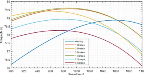
The torque-speed variations for healthy and faulty motors are given in Fig. 10. When the graph is examined, the change in starting, maximum and nominal torque values is clearly seen. Detailed change of starting torque is given inFig. 11, the detailed change of the maximum torque is shown inFig. 12, and the detailed change of the nominal torque is shown inFig. 13.
When the starting torque is examined, the highest starting torque is obtained from the 2 broken rotor bars with 56.1 N.m. The lowest torque is obtained from the healthy motor. The values obtained from other motors were around 54.1 N.m.
It is known that the pull-out slip in induction motors changes depending on the rotor resistance and the reactance. As can be seen from the figure, different pull-out slip values are obtained for various fault conditions. The speed of the motors is changing from 945 rpm to 1063 rpm at the pull-out point. The pull-out slip of the healthy motor is sd= 29%. The reason why these changes take place is the changes in resistance and reactance parameters.
4.10 4.20 4.30 4.40 4.50 4.60 4.70 4.80 4.90
Healthy 1 Broken 2 Broken 3 Broken 1 Scrape 2 Scrape 3 Scrape
I0
(A)
I0 (A)
Fig. 7. Change of no-load currents.
570 590 610 630 650 670 690 710
Healthy 1 Broken 2 Broken 3 Broken 1 Scrape 2 Scrape 3 Scrape
P o a n d Pk [W] Motors Po [W] Pk [W]
When the figures are examined, the most noticeable point is that the maximum torque obtained from the healthy motor is greater than that of the other faulty motors. The nominal torque value of the healthy motor is obtained to be 27 N.m and it is determined that this value is in accordance with the value given inTable 2.
74.2 74.7 75.2 75.7 76.2 76.7 77.2
Healthy 1 Broken 2 Broken 3 Broken 1 Scrape 2 Scrape 3 Scrape
E ffi ci en cy (%) Motors Efficiency (%)
Fig. 9. Change of efficiency.
Fig. 10. Torque-speed characteristic.
4.4. Harmonic Results
The variation of the total harmonic distortion for the current obtained from the Fluke 43-B power analyzer during the loaded operation test for healthy and faulty motors are given inTable 3. The harmonic variations for the current values of healthy motor, 3 broken rotor bars and 3 scraped motors are given inFig. 14(a), (b) and (c). The increase in distortion and harmonic current values which is occur in 3 broken rotor bars and 3 scraped motors is apparent in the Figures.
5. Conclusion
In this work, failure analysis of three-phase squirrel cage induction motors with 7 same powers and quantities was experimentally
Fig. 12. Detailed of maximum torque.
Fig. 13. Detailed of nominal torque.
Table 3
Current THD values during loaded operation.
Motors THD for current on loaded operation [%]
Healthy 3.8
1 Broken rotor bar 5.7
2 Broken rotors bars 6.5
3 Broken rotors bars 7.0
1 Scraped rotor 6.3
2 Scraped rotor 6.6
investigated. Three of these motors are faulty (broken rotor bars) at the intersection of the end ring and the rotor bars. The other three are the types of faulty brought about by the scraped only in the end ring. No-load, locked-rotor and loaded operation experiments are made for each motor type. According to the obtained results, an increase was observed in core losses and copper losses in both fault types. It was determined that efficiency values obtained from faulty motors decreased. In addition, an increase in the rated current values has been detected. However, in the case of current harmonic variations obtained from the loaded operation experiments, increases in the 5th and 7th harmonic amplitudes have occurred for faulty states. In loaded operation, the current THD is about twice as much degraded as healthy motor. In general, it has been determined that the number of broken rotor bars or the increase in the number of scraped rotors causes adverse effects on the machine performance.
In the future, the author will perform thermal analyzes to see the effects of faults on the motor temperature and performance for the healthy and faulty motors. It will also perform vibration analyzes for each motor types.
References
[1] O.G. Snehal, M.R. Salodkar, Review of detection of faults in induction motor, Int. Res. J. Eng. Technol. 03 (2016) 1771–1774.
[2] A. Hayri, O. Bilgin, Effects of rotor faults in squirrel-cage induction motors on the torque-speed curve, XIX International Conference on Electrical Machines-ICEM
2010, 1-5, Rome, 6–8 Sept. 2010.
[3] V.S. Dionysios, D.M. Epaminondas, A review on the faults of electric machines used in electric ships, Adv. Power Electron. 2013 (2013) 1–8. [4] A.A. Malik, Fault diagnosis of three-phase induction motor: a review, Opt. Spec. Issue: Appl. Opt. Signal Process. 4 (2015) 1–8.
[5] M.J. Picazo-Rodenas, R. Royo, J.A. Daviu, J.R. Folch, Use of the infrared data for heating curve computation in induction motors: application to fault diagnosis, Eng. Fail. Anal. 35 (2013) 178–192.
[6] A. Usudum, D. Bolukbas, The performance analyses of an induction motor due to specified fault conditions, 2013 8th International Conference on Electrical and Electronics Engineering (ELECO), 273–277, Turkey, 28–30, (Nov. 2013).
[7] M. Moradian, M. Ebrahimi, M. Danesh, M. Bayat, Detection of broken bars in induction motors using a neural network, J. Power Electron. 6 (2006) 245–252. [8] A. Glowacz, W. Glowacz, Z. Glowacz, Recognition of armature current of DC generator depending on rotor speed using FFT, MSAF-1 and LDA, Eksploatacja i
Niezawodnosc Maint, Reliab. 17 (2015) 64–69.
[9] Y. Hamed, G. Grellet, Detection of an end-ring fault in asynchronous machines by spectrum analysis of the observed electromagnetic torque, J. Phys. III, EDP Sci. 6 (1996) 443–448.
[10] I. Takeo, Failure Diagnosis of Squirrel-Cage Induction Motor with Broken Rotor Bars and End Rings, Chapter 5, 141–161.
[11]J. Tulicki, M. Sulowicz, N.P. Rylko, Application of the bispectral analysis in the diagnosis of cage induction motors, IEEE 13th Selected Issues of Electrical Engineering and Electronics (WZEE), 1–8, Rzeszow, Poland, 04–08, (May 2016).
[12]P.A.D. Arredondo, D.M. Sotelo, R.A.O. Rios, J.G.A. Cervantes, H.R. Gonzalez, R.J.R. Troncoso, Methodology for fault detection in induction motors via sound and vibration signals, Mech. Syst. Signal Process. 83 (2017) 568–589.
[13]A. Glowacz, W. Glowacz, Z. Glowacz, J. Kozik, Early fault diagnosis of bearing and stator faults of the single-phase induction motor using acoustic signals, Meas. 113 (2018) 1–9.
[14]S. Prainetr, S. Wangnippanto, S. Tunyasirut, Detection mechanical fault of induction motor using harmonic current and sound acoustic, IEEE 5th International Electrical Engineering Congress, 1-4, Pattaya, Thailand (Mar. 2017) 8–10.
[15]M. Amina, M. Jarboui, A. Masmoudi, Broken bar and end-ring faults: analysis of their effects on the rotor cage currents, COMPEL: Int. J. Comput. Math. Electr. Electron. Eng. 34 (2015) 1771–1795.
[16]V.P. Mini, S. Ushakumari, Rotor fault detection and diagnosis of induction motor using fuzzy logic, AMSE J. 2014 Ser. Modell. A. 87 (2014) 19–40. [17]A. Glowacz, Acoustic based fault diagnosis of three-phase induction motor, Appl. Acoust. 137 (2018) 82–89.
[18]Y. Merizalde, L.H. Callejo, O.D. Perez, State of the art and trends in the monitoring, detection and diagnosis of failures in electric induction motors, Energies. 10 (2017) 1–34.
[19]J.R. Magdaleno, H.P. Barreto, J.R. Cortes, I.C. Vega, Hilbert spectrum analysis of induction motors for the detection of incipient broken rotor bars, Meas. 109 (2017) 247–255.
[20]J.R.R. Guillen, J.J.D.S. Perez, J.P.A. Sanchez, M.V. Rodriguez, R.J.R. Troncoso, Enhanced FFT-based method for incipient broken rotor bar detection in induction motors during the startup transient, Meas. 124 (2018) 277–285.
[21]H. Arabacı, O. Bilgin, Automatic detection and classification of rotor cage faults in squirrel cage induction motor, Neural Comput. Appl. 19 (2010) 713–723. [22]L. Maraaba, Z. Al-Hamouz, M. Abido, An efficient stator inter-turn fault diagnosis tool for induction motors, Energies. 11 (2018) 1–18.
[23]V.S. Dionysios, K.N. Gyftakis, J. Kappatou, E.D. Mitronikas, The influence of the broken bar fault on the magnetic field and electromagnetic torque in 3-phase induction motors, 2012 XXth International Conference on Electrical Machines (ICEM), 1868–1874, France, 2–5, (Sept. 2012).
[24]Y. Xie, Z. Wang, X. Shan, Y. Li, Investigation of rotor thermal stress in squirrel cage induction motor with broken bar faults, COMPEL-Int, J. Comput. Math. Electr. Electron. Eng. 35 (2016) 1865–1886.
[25]G. Singh, V.N.A. Naikan, Detection of half broken rotor bar fault in VFD driven induction motor drive using motor square current MUSIC analysis, Mech. Syst. Signal Process. 110 (2018) 333–348.
[26]A. Glowacz, W. Glowacz, Z. Glowacz, J. Kozik, M. Gutten, D. Korenciak, Z.F. Khan, M. Irfan, E. Carletti, Fault diagnosis of three phase induction motor using current signal, msaf-ratio15 and selected classifiers, Arch. Metall. Mater. 62 (2017) 2413–2419.
[27]T. Aroui, Y. Koubaa, A. Toumi, Magnetic coupled circuits modeling of induction machines oriented to diagnostics, Leonardo J. Sci. 13 (2008) 103–121. [28]J. Faiz, B.M. Ebrahimi, M.B.B. Sharifian, Time stepping finite element analysis of broken bars fault in a three-phase squirrel-cage induction motor, PIER Prog,
Electromagnet. Res. 68 (2007) 53–70.
[29]Z.Y.M. Hurtado, C.P. Tello, J.G. Sarduy, A review on location, detection and fault diagnosis in induction machines, J. Eng. Sci. Technol. Rev. 8 (2015) 185–195. [30]K.S. Gaeid, H.W. Ping, Wavelet fault diagnosis and tolerant of induction motor: A review, Int. J. Phys. Sci. 6 (2011) 358–376.
[31]A. Sharma, S. Chatterji, L. Mathew, M.J. Khan, A review of fault diagnostic and monitoring schemes of induction motors, Int. J. Res. Appl. Sci. Eng. Technol. 3 (2015) 1145–1152.
[32]P.S. Bhowmik, S. Pradhan, M. Prakash, Fault diagnostic and monitoring methods of induction motor: a review, Int. J. Appl. Control Electr. Electron. Eng. 1 (2013) 1–18.
[33]H.H. Hanafy, T.M. Abdo, A.A. Adly, 2D finite element analysis and force calculations for induction motors with broken bars, Ain Shams Eng. J. 5 (2014) 421–431.
[34]M. Akar, I. Cankaya, Broken rotor bar fault detection in inverter-fed squirrel cage induction motors using stator current analysis and fuzzy logic, Turk. J. Electr. Eng. Comput. Sci. 20 (2012) 1077–1089.
[35]M.A. Juneghani, B.K. Boroujeni, M. Abdollahi, Determination of number of broken rotor bars in squirrel-cage induction motors using adaptive neuro-fuzzy interface system, Res. J. Appl. Sci. Eng. Technol. 4 (2012) 3399–3405.
[36]S. Dmitry, W. Chen, Y. Liu, O. Liukkonen, Finite element analysis of end ring impedance in squirrel cage induction machines, IEEE Energy Conversion Congress and Exposition (ECCE), 254–259, USA, 28, (Oct. 2013).