246 IEEE TRANSACTIONS ON CIRCUITS AND SYSTEMS FOR VIDEO TECHNOLOGY, VOL. 4, NO. 3, JUNE 1994
3-D Motion Estimation and Wireframe
Adaptation Including Photometric Effects for
Model-Based Coding
of
Facial Image Sequences
Gozde
Bozdagi,
Member, IEEE,A.
Murat Tekalp, Senior Member, IEEE, and Levent OnuralAbstruct- We propose a novel formulation where 3-D global and local motion estimation and the adaptation of a generic wireframe model to a particular speaker are considered simul- taneously within an optical flow based framework including the photometric effects of the motion. We use a flexible wireframe model whose local structure is characterized by the normal vectors of the patches which are related to the coordinates of the nodes. Geometrical constraints that describe the propagation of the movement of the nodes are introduced, which are then efficiently utilized to reduce the number of independent structure parameters. A stochastic relaxation algorithm has been used to determine optimum global motion estimates and the parameters describing the structure of the wireframe model. Results with both simulated and real facial image sequences are provided.
I. INTRODUCTION
UE to growing interest in very low bit rate digital video
D
(about 10 kbitsls), a significant amount of research has focused on model-based video compression [ 11-[ 121. Scien- tists became interested in model-based coding because the quality of digital video obtained by hybrid coding techniques, such as CCITT Rec. H.261 [13], is deemed unsatisfactory at these very low bit rates. Studies in model-based coding employ object models ranging from general purpose 2-D or 3-D models [2], [lo], [ l l ] to application specific wireframe models [3]-[9]. One of the main applications of model-based coding has been the videophone, where scenes are generally restricted to head and shoulder type images. In videophone applications, it is common to represent the head and shoulders of the speaker by a specific wireframe model which is present at both the receiver and the transmitter. Then, 3-D motion and structure estimation techniques are employed at the transmitter to track the motion of the wireframe model and the changes in its structure from frame to frame. The estimated motion and structure (depth) parameters along with changing texture information are sent and used to synthesize the next frame in the receiver side.Traditionally, the scaling of a generic wireframe model to the actual speaker and motion estimation have been handled Manuscript received November 1, 1993; revised April 16, 1994. It was supported by NATO International Collaborative Research Grant N 900012 and by TUBiTAK under the COST 211 project and was recommended by Prof. Hans Georg Musmann.
G. Bozdagi and L. Onural are with the Electrical and Electronics Engineer- ing Department, Bilkent University, 06533 Bilkent, Ankara, Turkey.
A. M. Tekalp is with the Electrical Engineering Department, University of Rochester, Rochester, New York, 14627 USA. He was a visiting Associate Professor at Bilkent University during the progress of this work.
IEEE Log Number 9402882.
separately. Many of the existing methods consider scaling a generic wireframe to the actual speaker using only the initial frame of the sequence [3], [14]. Thus, the scaling in the z-direction (depth) is necessarily approximate. The scaling procedure first proposed by Aizawa et al. [3] involves manual steps, while Reinders et al. [14] later proposed an automated procedure. For subsequent frames, first the 3-D global motion of the head is estimated under rigid body assumption, using either point correspondences [3], [6], [12] or optical flow based formulations [7], [8]. A general overview of 3-D rigid body motion and structure estimation methods can be found in [15]. Then, local motion (due to facial expressions) is estimated making use of action units (AU) described by Facial Action Coding System (FACS) [8]. Recently, Li et al. [9] proposed a method, to recover both the local and global motion parameters from the spatio-temporal derivatives of the image, which also requires a priori knowledge of the AU’s. Finally, provisions
for texture update for regions where the model-based approach fails are considered.
In this paper, we propose a novel formulation where 3- D global and local motion estimation and the adaptation of the wireframe model are considered simultaneously within an optical flow based framework including the photometric effects of motion. Although, the utility of photometric cues in 3-D motion and structure estimation are well-known [ 161-[ 191, photometric information was not used in the context of mo- tion estimation for videophone applications before. The main contributions of this paper are: (i) a flexible 3-D wireframe model has been used where the X , Y and 2 coordinates of the nodes of the wireframe model are allowed to vary from frame to frame so as to minimize the error in the optical flow equation, and (ii) photometric effects are included in the optical flow equation. The proposed adaptation of the wireframe model serves for two purposes that cannot be separated: to reduce the misfit between the wireframe model and the facial region in frame k - 1, and to account for the local motion deformations from frame k - 1 to frame k without using any a priori information about the AU’s.
The simultaneous estimation formulation is motivated by the fact that estimation of the global motion, local motion and adaptation of the wireframe model including the depth values are mutually related; thus a combined optimization approach is necessary to obtain the best results. Because an optical flow based criterion function is utilized, computation of the synthesis error is not necessary from iteration to iteration; 1051-8215/94$04.00 0 1994 IEEE
I
BOZDA6I er al.: 3-D MOTION ESTIMATION AND WIREFRAME ADAPTATION 247
thus, resulting in an efficient implementation. The synthesis error at the conclusion of the iterations is used to validate the estimated parameters, and to decide whether a texture update is necessary.
In Section 11, we review the optic-flow based approach to 3-D motion and structure estimation and briefly discuss a photometric image formation model. Estimation of the illumi- nant direction is summarized in Section 1I.C. The formulation of simultaneous motion estimation and wireframe adapta- tion problem including the photometric effects of motion is presented in Section 111. The algorithm for the proposed si- multaneous estimation including an efficient method to update the nodes of the wireframe model is given in Section IV.
Experimental results on simulated and real video sequences are presented in Section V to demonstrate the effectiveness of the proposed methods.
11. BACKGROUND A. 3-0 Motion and Structure from Optical-Flow
In this section, we will review the equation describing the relation between the 3-D motion and structure and the corresponding 2-D velocity field (optical flow), which is related to the projection of the 3-D motion onto the image plane under certain assumptions [ 161. By using additional constraints regarding the 3-D structure of the scene, it is possible to recover the parameters of the 3-D motion from
the associated optical flow field [15].
Zs(t)lT be the vector of the 3-D coor- dinates of a particular point s of a moving object at time
t
and S refers to the object which is the set of all such points. If we assume that the object is rigid and subject to small rotation, we can express the position of s at timet
+
At given its position at time t as,Let [ X s ( t ) Ys(t)
Zs(t
+
At) w y -wx 1where W X , w y , and wz are the rotational displacements about the X , Y and 2 axes, respectively, and T x , Ty, and TZ are the translational displacements along the X , Y and 2 axes, respectively. Then, the 3-D velocities are approximated by
W Y -wx
where X,(t) = X,(t+At)-X,(t), Ys(t) = Ys(t+At)-Ys(t), Z,(t) = Z s ( t
+
At) - Z s ( t ) , and At = 1. Under orthographic projection along the z-direction, we can represent the 2-D velocity field associated with the projection of the point s as;.s(t) = wzys(t) - WY&(t)
+
TxYs(t) = -wzzs(t)
+
w x Z s ( t )+
TY (3) where z s ( t )A
X,(t), ys(t) Ys(t).Now, let us represent the intensity at point ( x s ( t ) , ys(t))
by I ( z s ( t ) , ys(t),
t).
Assuming that I ( x S ( t ) , y s ( t ) , t ) does not change in time, we can write,I ( z s ( t ) , y s ( t ) ,
t )
= constant; V t , and Vs E S. (4) or in other words,v s E
s.
(5)Since the above equations are valid for all s E S , from now on we will drop the subscript s to simplify the equations. Using the chain rule of differantiation, we can write (5) as
I,;.
+
I Y Y+
It = 0, (6)where I,,
IY,
and It are the partial derivatives of image intensity, I , in z, y and t , respectively. Substituting (3) into(6), we get
I , ( w z ~ - W Y Z
+
T x ) + l y ( - ~ z z+
W X Z+
T y )+
It
= 0. (7)Eq. 7 is a constraint that relates the spatio-temporal image
gradients to the 3-D motion w,, w y , w,
,
T,, TY and structure (2) parameters under the assumption that the variation in image intensity pattern is solely due to the 3-D motion of the underlying scene.Eq. (7) alone is not sufficient to determine the 3-D motion and structure parameters if they are allowed to change freely and independently at every point. Several approaches exist in the literature to compute the motion and structure parameters from (7) under piecewise rigid scene assumption (constraining the variation of the 3-D motion parameters) and with certain surface structure models (constraining the variation of 2 with
( X , Y ) ) [151-[211.
B. Photometric Model of Image Formation
The above formulation neglects the effects of changing shading due to the 3-D motion of the scene. For example, in the case of rotational motion because the surface normals change, the shading of the objects varies even if the external illumination remains constant. Recently Pentland [ 181 showed that the changes in image intensity because of photometric effects can dominate intensity changes due to geometric effects of motion (changes in projected surface geometry due to 3-
D motion). Similar discussions can be found in [16], [171, [19]. Here we briefly discuss a photometric model of image formation with the aim of incorporating photometric effects into the above optical flow based formulation.
The image intensity associated with the point s (described in the previous section) can be represented through a reflectance map
I(xs(t11 ys(t), t ) = R ( P S ( t ) , 4s(t)) (8)
where
R
denotes the reflectance map function, and p = and q = are the partial derivatives of depth ZS(t) with respect to the image coordinates z and y respectively. Under the assumptions of orthographic projection onto the image248 IEEE TRANSACTIONS ON CIRCUITS AND SYSTEMS FOR VIDEO TECHNOLOGY, VOL. 4, NO. 3, JUNE 1994
-611
-
SI2
E;]
= (BtB)-lBt:
- S I N-
plane and a Lambertian surface with constant albedo, p, we can express the reflectance map as [22]
(9) where
L'
= ( L z , L,, L,) is the unit vector in the mean illuminant direction and $ is the unit surface normal of the object at point s given byR ( p s ( t ) , q s ( t ) ) = PNSlt)
.
L'
N s l t ) = ( - p s ( t ) , - 4 s ( t ) , l)/(p?(t)
+
q,2(t)+
w2.
(10)Note that the illuminant direction can also be expressed in terms of tilt and slant angles as
+
L = (L,,L,,L,) = (cosrsina,sinTsina,cosa) ( 1 1 ) ?here r , the tilt angle of the illuminant, is the angle between L and the+X
-
Z plane, and a, the slant angle, is the angle between L and the positive 2 axis.The model (9) is widely used in the computer vision literature for estimating the object shape and the illuminant direction from shading in case of diffuse reflection [18].
Moreover, its simple functional form makes it popular than specular models which are mainly used when the surface is shiny.
-Sz1 SYl
-
6x2 SY2
,
and B =- 6 x N S y N d
C. Estimation of Illumination Direction
In order to incorporate the photometric effects of motion into 3-D motion estifnation and wireframe adaptation, the illuminant direction L must be known or estimated from the available frames. In this study, we use the method proposed by Zheng et al. [25] to estimate the illuminant direction.
The method to estimate the tilt angle is based on approxi- mating the surface by spherical patches. The reason for using locally spherical patches is to begin from an initial state close to the true surface shape in order not to be stuck in a local minimum. An estimate of the tilt angle is given by
since f 3 ( ~ ) (defined in [25]) is a monotonically decreasing function of a, where E { I } and E { 1 2 } are the expected values of the image intensities and the square of the image intensities, respectively, estimated from the image area where the wireframe model is fitted. Finally, the surface albedo can be estimated from
where f1(0) and f2 ( (T) are seventh order polynomials in cos (T
as defined in [25].
111. PROBLEM FORMULATION
In this section we present the proposed formulation for simultaneous estimation of 3-D global motion parameters and the adaptation of the wireframe model which also takes the presence of local motion into account. The inclusion of the photometric effects into the optical flow equation is discussed in Section 1II.A. In Section III.B, we introduce geometrical constraints about the structure of the wireframe model and formulate the problem.
A. Incorporation of the Photometric Effects
Since we represent the 3-D structure of the head and shoulders scene by a wireframe model and the surface of the wireframe model is composed of planar patches, the variation in the intensity of a pixel due to photometric effects of motion will be related to a change due to motion in the normal vector of the patch that this pixel belongs to using the image formation model (9).
From (10) and ( l l ) , we can write the change in the normal vector associated with the point s due to the 3-D motion as
d N s l t ) = d ( X s ( t
+
At), Ys(t+
At), Z s ( t+
A t ) ) - fis(Xs(t), Ys(t), ZS(t>) - (-ps(t), - q s ( t ) ,UT
- - ( - p s ( t+
At), q s ( t+
At), ( p s ( t ) 2+
q s ( t ) 2+
1 ) 1 / 2 ' ( p s ( t+
A t ) 2+
qs(t+
A t ) 2+
1)ll2 (15)where using orthographic projection p s ( t ) =
w ,
q s ( t ) = ay. ( t ) anda Z S ( t
+
A t )-
-WY+
p s ( t )d z s ( t
+
A t ) 1+
W y p s ( t )p s ( t
+
At) = -Assuming that the mean illuminant direction
L'
=( L z , L,, L,) remains constant, we can represent the change in intensity due to photometric effects of motion using (9) as
Then, combining (6) and (17), dropping the subscript s for simplicity and denoting p(t
+
At) as p', q ( t+
At) as q', p ( t )I
BOZDAGI et al.: 3-D MOTION ESTIMATION AND WIREFRAME ADAPTATION
and
249
as p, q ( t ) as q, we include the photometric effects into the optical flow based formulation as
I,(w,Y
-
wVZ
+
T,)+
Iy(-w%x+
w,Z
+
T y ) + I tThe term on the right hand side of (18) may be significant especially if the change in the surface normal has components either toward or away from the illuminant direction [ 181. B. Structure of the Wireframe Model and Problem Statement
The wireframe model is composed of triangular patches which are characterized by the
(X,
Y,
2 ) coordinates of their respective vertices. Given the(X,
Y,
2 ) coordinates of the vertices of a patch, we can write the equation of the lane containing this patch. LetPii)
=(Xii',
YJi),
Zf'), PF)
= vertices of the ith patch, and P(') =(Xi,
y Z ,Zi)
be any point on this patch. Then,(X(2) y(2)
z(i))
andPii)
=(X(i)
y(i)z(i))
denote the2 , 2 9 2 3 , 3 , 3
gives the equation of the plane containing
Pf),
Pii'
andPf),
whereP(i$ii), P,(i$$),
andPFGf)
are the vectors from the former point to the latter, respectively. We can express this equation in the form(19)
zi
= pixi+
qiy,+
Ci,where (see top of page).
Using (19), the Z coordinate of any point on the ith patch can be expressed in terms of the parameters p i , q; and ci and the
X
andY
coordinates of the point. Then, we can eliminate2
from (18) by substituting (19) into (18) withXi
= xi,yZ = yi, where the patch index i is determined for each (2, y)
according to the orthographic projection.
The problem of simultaneously estimating the 3-D global motion parameters w,
,
w y,
w, , T,,
Ty
, describing the global motion of the head, and the parameters p i , qi, ci, that describe the structure of the wireframe model, can then be formulated as to minimize the sum square error in the optical flow equation (1 8) over all pixels in a frame given bywhere (see (21) above)
with respect to the variables w,, w y , w,,
T,,
T,,p,,
q,, c, andi
= 1,.. .
,
number of patches. It is important to note that the surface normals p a , q, and the translation (in the Z direction) parameters c, of each planar patch of the wireframe are not completely independent of each other. Each triangular patch is either surrounded by two (if it is on the boundary of the wireframe) or three other triangles. The requirement that the neighboring patches must intersect at a straight line imposes a constraint on the structure parameters of these patches in the formPaxaj
+
qayzj+
ca = Pjxaj+
qjyzj+
cj ''q22)where p3, qJ and cj denote the structure parameters of the jth patch, and ( x a J , yv) denote the coordinates of a point that
250 IEEE TRANSACTIONS ON CIRCUITS AND SYSTEMS FOR VIDEO TECHNOLOGY, VOL. 4, NO. 3, JUNE 1994
lie on the intersection of the ith and jth patches. Eq. 22 not only enables us to preserve the structure of the wireframe during the adaptation, but also facilitates the reduction of the number of independent unknowns in the optimization process. An efficient algorithm to reduce the number of independent unknowns using (22) is given in Section IV.
The perturbation of the structure parameters p i , q; and ci for each patch i results in a change in the coordinates of the nodes of the updated wireframe. The new coordinates
(X,,
Y,,
Zn)
of the node n can be computed given the updated structure parameters of three patches that intersect at node n. Let the patches i, j and k intersect at node n. Then, the relations
pix,
+
qiyn+
ci = p j X ,+
qjYn+
cjpix,
+
qiyn+
cz = p k x n+
q k y n+
ck (23)specify X , and Y,. The coordinate 2, can be computed using (19) for any of the patches i , j or k . It is this updating of the coordinates of the nodes that allows the adaptation of the wireframe model to lower the misfit error and accomodate the presence of local motion, such as the motion of the eyes and the mouth.
IV. METHOD
In this Section a stochastic relaxation algorithm to esti- mate the global motion parameters w,
,
wy,
w,,
T,,
Ty , and the structure parameters p i , qi,
ci, by minimizing the error in the optical flow equation E given by (20), is proposed using the values of p and (LzlL,,
L,) that are estimated according to Section 1I.C. Stochastic relaxation is an iterative technique to find the global optimum for complex optimization problems. Each iteration consists of perturbing the state of the system in some random fashion [26]. In our experiments, the independent unknowns are perturbed at each iteration, where the perturbations are generated as samples of Gaussian distributed numbers with the variance of the distribution adjusted according to the value of the cost function E (given by (20)). Further, the magnitude of perturbations is reduced with the number of iterations, so that convergence should result.As stated in Section III.B, not all of the parameters p i , q;
,
ciare independent due to the geometrical constraints defining the structure of the wireframe model given by (22). The dependent structure parameters are determined as follows: At each iteration cycle, we visit all the patches of the wireframe model in sequential order. If, at the present iteration cycle, none of the neighboring patches of patch i has yet been visited for updating their structure parameters (e.g., the initial patch), then p i , q;, c; are all independent and are perturbed. If only one of the neighboring patches, say patch j , has been visited (pi, q j , c j have already been updated), then two of the parameters, say pi and qi are independent and perturbed. The dependent variable c; is computed from (22) as
(24)
where x i j is one of the nodes common to both patches i and j , that is either in the boundary or has been already updated in the present iteration cycle. If two of the neighboring patches, say
ci = P j X i j
+
qjj.yij+
cj - P i X i j-
q i y i j ,patches j and IC, have already been visited, i.e., the variables
p j , q j , cj and p k , q k , Ck have been updated, than only one
variable, say pi, is independent and perturbed. Then, c; can be found from (24), and q; can be evaluated as
where X ; k is one of the nodes common to both patches i and k , that is either in the boundary or has been already updated in the present iteration cycle.
The change in the structure parameters p i , qi, ci affect the location of the nodes. At each iteration cycle, the coordinates of a node are updated as soon as the structure parameters of three patches that intersect at that node are updated using (23).
Thus, the new X and Y coordinates of the nodes are given by
The new Z coordinate can be computed from (19) given the
X
and Y coordinates and the p ; , q i , ci for any patch passing through that node.In the following we summarize the proposed algorithm as: 1) Estimate the illumination direction using (12) and (13),
and the surface albedo using
(14).
2) Initialize the coordinates of the nodes ( X n , Y,, Zn), for all n, using an approximately scaled initial wireframe model. Set the iteration counter m = 0.
3) Determine the initial motion parameters using the sto- chastic relaxation method described in [ 121 (or any other point correspondence method to compute the motion parameters using a set of selected nodes given their depth values).
4) Compute the value of the cost function E given by (20).
5 ) If E
<
E, stop.Else, set m = m
+
1 andperturb the motion parameters w = [U,, wy
,
w,, T,, TylTas
(27)
where cy is a constant, A = N ( 0 , &,J), i.e., zero mean Gaussian with variance a'(,), where a'(,) = E , and the structure parameters p ; , q; and c; as
Define count-i as the number of neigh- boring patches to patch i whose struc- ture parameters have been perturbed. Set count-i=O, €or all patches i.
Perturb p-1, q-1, c-l as
W ( m )
-
q m - 1 )+
am&P l ( m )
-
P l ( m - l )+
cymal,a(,)
-
q l ( m - l J+
Qmnllwhere Ai = Ni(O,n:'"'), i.e., zero mean Gaussian with variance czz(mJ, where gtz(m) = ~ ~ x , y ) E
BOZDA61 et al.: 3-D MOTION ESTIMATION AND WIREFRAME ADAFTATION 25 1
for (i=2) to number of patches if (counti = 1) {
perturb p-i and q-i
increment count-m, for all m denoting neighbors of patch i
Compute c i using Eq. 27 where the x and y coordinates are that
of a fixed or a precomputed node on the intersection line
between patch i and j }
if (count2 == 2 ) ) { perturb p-i
increment count-m, for all m denoting neighbors of patch z Compute c-i using Eq. 27 and q-z using Eq. 28 where x-ij,g-zj
and x - i k , y i k are coordinates of a fixed or a precomputed node
on the intersection line between patches i , j and i , k
respectively.
1
If p-z,q-z, and c-i €or at least three patches intersecting at a node are
updated, then update the coordinates of the node by using Eq. 28. }
increment count-j, for all j denoting neighbors of patch 1 (con’t top of this page). 6) Go to (4).
Experimental results will be presented in the next section to demonstrate the performance of the proposed method.
v.
&SULTSWe have demonstrated the proposed method with both real and synthetic image sequences. The real image sequences are “Miss America” and “Claire” where each frame consists of
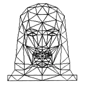
256 x 256 and 352 x 288 pixels, respectively. The synthetic sequence is generated by moving (the vertices corresponding to the head area) and shading the wireframe (Fig. 1) which is an extension of the CANDIDE wireframe [27] and composed of 217 triangles and 144 nodes [ 5 ] . In the simulations, we set
(Y = 0.95 to obtain the reported results. In each case, the con-
vergence is achieved in about 100 iterations. The experimental results are summarized in the following subsections.
A. Simulation Results
According to our model, the synthesis error in model-based image synthesis originates from: (i) misfit of the wireframe, (ii) error in global motion estimation, (iii) error in local motion estimation, and (iv) the photometric effects of the motion. The following set of simulation experiments is intended to test each of these causes in a controlled manner. The experiments with the synthetic image sequences show the performance of the algorithm in case of global motion only, global and local motion, with and without incorporating illumination effects. On the other hand, the real image sequences used in the experiments have both global motion, local motion and illumination effects. These set of experiments enables us to
Fig. 1. The wireframe model.
see whether the consideration of illumination is useful and effective for the real image sequences for motion and structure estimation.
first simulation tests the accuracy of the proposed method for global motion estimation by eliminating all other sources of error. To this effect, we generate an image frame by taking the orthographic projection of the wireframe in Fig. 1, and painting its patches by black and white altematingly. Since the image is obtained directly from the wireframe itself, there is no fitting problem, and therefore, no misfit. The next frame is obtained by rotating and translating the wireframe using a given set of motion parameters and computing the projection of the wireframe in this new position. No local motion or shading effects are simulated. Table 1 shows the
I
%
w ,
252 IEEE TRANSACTIONS ON CIRCUITS AND SYSTEMS FOR VIDEO TECHNOLOGY, VOL. 4, NO. 3, JUNE 1994
True motion Initial point Our method Percentage Error
-0.1 -0.08894 -0.1046 4.61
0.35 0.3368 0.3526 0.76
Fig. 2. clockwise (a) The first and (b) the second frames of the synthetic image sequence with global motion; (c) the initial wireframe and (d) the rotated wireframe through the estimated motion parameters pasted on the first and the second frames respectively.
Fig. 3. clockwise (a) The first and (b) the second frames of the synthetic image sequence with globaland local motion; (c) The initial wireframe and (d) the rotated wireframe through the estimated motion parameters pasted on the first and the second frames respectively.
True motion Initial point -0.1 -0.08894
u.. 0.35 0.3368
TABLE I
GLOBAL MOTION ESTIMATION WlTH THE SYNTHETIC SEQUENCE
Our method
I
Percentage Error -0.1072I
7.15 0.3461 I 1.104 W, T, TY -0.03 -0.0113 -0.030641 2.13 6 4.962 5.9860 0.23 -3 -2.8999 -2.9791 0.69true and estimated motion parameters. “Initial point” indicates the motion parameters at the beginning of the iterations, and “Result” shows the estimated parameters at convergence. The “Percentage error” gives the percentage deviation of our results from the true values. The first and the second frames are shown in Fig. 2(a) and 2(b). The initial wireframe, and, the rotated wireframe with the estimated motion parameters, are shown on their corresponding frames in Fig. 2(c) and 2(d). The mean square synthesis error between the actual second frame I a ( x l y) and the synthesized second frame Is(z, y) is computed according to
L - I
W , -0.03 -0.0113 -0.02724 9.19
TS 6 4.962 5.8697 2.17
Tu -3 -2.8999 -2.9737 0.87
where N and M show the x and y extends of the image, respectively. The MSE in this case is 5.062.
The next simulation tests the ability of our method to track the local motion deformations. For this purpose, in addition to the above global motion, the action units (AU) 17 and 46, corresponding to chin raiser and winking, are also synthesized. Table I1 shows the true and estimated global motion parame- ters. The first and the second frames together with the initial wireframe and the rotated and modified wireframe through the
TABLE I1
GLOBAL AND LOCAL MOTION ESTIMATION WITH THE SYNTHETIC SEQUENCE
estimated motion parameters pasted on the first and the second frames respectively are also shown in Fig. 3. The MSE is computed to be 5.579.
Simulations With the “Miss America ” Sequence
With no photometric effects
After getting successful results from the previous experi- ment we tested our algorithm, again for global and local mo- tion tracking performance, using a textured 3-D model instead of the previous bare wireframe model. The textured model is obtained by mapping a single frame from the “Miss America” sequence to the initial wireframe model. The mapping is accomplished after scaling the wireframe model approximately to the location and the size of the face by positioning four extreme points, interactively. A second frame is obtained from the first one by rotating and translating it. Then we applied our algorithm to check its performance in finding these already known motion parameters. The results of global motion estimation with no local motion and no photometric effects is presented in Table 111. In addition, we have synthe- sized a new frame from the first frame using the estimated motion parameters and computed the difference between this synthesized frame and the second frame. The MSE is found
BOZDAGI et al.: 3-D MOTION ESTIMATION AND WIREFRAME ADAPTATION 253
Fig. 4. clockwise (a) The first frame of “Miss America”, (b) simulated second frame with global and localmotion (without photometric effects); (c) synthesized second frame using the estimated motion and structure parameters.
Fig. 5. clockwise (a) The first frame of “Miss America”, (b) simulated second frame with global and local motion, and the photometric effects; (c) synthesized second frame using the estimated motion and structure parameters. TABLE III
GLOBAL MOTION ESTIMATION WITH THE SIMULATED MISS AMERICA SEOUENCE WITHOUT THE PHOTOMETRlC EFFECTS
TABLE 1V
GLOBAL AND LOCAL MOTION ESTIMA~ON WITH THE SIMULATED MISS
We repeat the above experiment by including local motion specified by the AU2, AU17 and AU46 which correspond to outer brow raiser, chin raiser and winking. By this way, we are able to test how local deformations affect the 3-D global
motion and structure parameter estimation and whether we can track these deformations. Table IV shows the true and estimated global motion parameters. The first, second, and the synthesized frame in this case are shown in Fig. 4. The MSE between the second and the synthesized frames is now equal to 7.554.
With photometric effects: The purpose of this set of sim-
ulations is to see whether there is an improvement or not when the illumination effects are also considered. To simulate the photometric effects, we estimate the direction of the illuminant from the first frame. The estimated tilt and slant angles are 141.131 and 72.5064 which correspond to
L
= (-0.74257,0.59851,0.33059). The 3-D object of the firstframe is again rotated and translated (with or without local motion) as done in the previous experiment, but this time the object is shaded using (8) according to the change in the
surface normal vectors due to rotation (assuming the direction of the illuminant remains constant). Tables V and VI show
the results of global motion estimation both without and with
AMERICA SEQUENCE WITHOUT THE P H O T O M E ~ C EFFECTS
TABLE V
GLOBAL MOTION ESTIMATION WITH THE SIMULATED MISS
AMERICA SEQUENCE INCLUDING THE PHOTOMETRIC EFFECTS
local motion. In the case of local motion, we again use the
AU 2, 17 and 46 which correspond to outer brow raiser, chin raiser and winking, respectively. The second and synthesized frames using estimated parameters are shown in Figs. 5 in the case with local motion. The MSE are found to be 5.839 and 7.101, for the experiments without and with local motion, respectively.
B. Results With Real Image Sequences
Experiments With
Two
Frames of the “Miss America” Se- quence: Now, we test our algorithm using the first and the-
254
w,
W,
T,
IEEE TRANSACTIONS ON CIRCUITS AND SYSTEMS FOR VIDEO TECHNOLOGY, VOL. 4, NO. 3, JUNE 1994
. . . ~ . _ . ~.
0.35 0.3368 0.34001 2.85
-0.03 -0.0113 -0.0272 9.28
6 4.962 6.4660 7.76
Fig. 6.
of the real “Miss America” sequenceincluding the photometric effects. clockwise (a) The first, (b) tenth, andthe (c) synthesized tenth frame
Fig. 7.
of the real “Miss America” sequencewithout the photometric effects. clockwise (a) The first, (b) tenth, and the (c) synthesized tenth frame
and second frames in our algorithm. Here, there exists both global and local motion. Further, since the second frame is not artifically synthesized, there is also additional wireframe misfit error. To see the importance of incorporating the photometric effects into the optical flow equation, we repeat the experiment once ignoring the photometric effects and once taking them into account. Tables VI1 and VI11 show the estimated global
TABLE VI
GLOBAL AND LOCAL MOTION ESTLMATION WITH THE SIMULATED MISS AMERICA SEQUENCE INCLUDING THE PHOTOMETFX EFFECTS
11
True motion11
Initial pointI
Our methodI
Percentage Errorn
-0.1 II -0.08894 1 -0.1079 I 7.90I
T..n
-3 I1 -2.8999 I -2.8852 I 3.82I
THE
TABLE W
AMERICA SEQUENCE INCLUDING THE F’HOWMETRIC E m c r s
ESTIMATED GLOBAL MOTION PARAMETERS WITH THE REAL MISS
TABLE VIII
THE ESTIMATED GLOBAL MOTION PARAMETERS WlTH THE REAL MISS AMERICA SEQUENCE WITHOUT THE PHOTOMETRIC EFFECTS
0.908
U
0.7648T, 1.4827 2.6144
motion parameters with and without considering the photo- metric effects, respectively. The synthesized images using the estimated motion and structure parameters are depicted in Fig. 6 and Fig. 7 and the MSE are 5.81658 and 6.23229, respectively. The MSE’s are calculated only using the region of the image pasted on the wireframe.
Motion Trucking Experiments With the “Claire” Sequence:
Finally, we test our method on a longer sequence using the first 16 frames of the “Claire” sequence. Every second frame of this sequence is shown in Fig. 8. In the beginning Claire looks straight into the camera. Later, she turns her head to the left. There are also some facial movements such as blinking and openning of the mouth. A frame consists of 352 x 288 pixels (which is the CIF picture format). Only the luminance component is used in the experiments. Our task is to track the motion of the head and extract the facial expressions. Fig. 9 shows the synthesized image sequence using the estimated parameters. The MSE for the frames used in the experiment are 6.98, 7.17, 8.06, 8.27, 8.21, 8.77, 9.48. Upon viewing the two sequences, the difference is hardly noticable.
VI. DISCUSSION AND CONCLUSION
Our goal in this paper has been to estimate the 3-D structure and motion of an head and shoulder type scene with the highest possible accuracy based on two frames in order to predict the second frame from the first. We start with a wireframe model developed for a generic head and shoulders type scene. We address the problem of fitting this generic wireframe model to the actual speaker in the scene, by flexibly adjusting its configuration in both
X ,
Y , and 2 directions,I
BOZDAGI et al.: 3-D MOTION ESTIMATION AND WIREFRAME ADAPTATION
Fig. 8. image sequence.
Every second frame of the first 16 frames of the original “Claire”
Fig. 9.
structure parameters.
The synthesized “Claire” sequence using the estimated motion and
simultaneously with estimating its 3-D motion based on two frames. The proposed algorithm not only minimizes the misfit of the wireframe model to the speaker in the first frame but also adjusts the configuration of the wireframe model to adapt for the local motion deformations from the first to the second frame. The simultaneous estimation framework developed in this paper promises the highest possible estimation accuracy due to the inherent connection between the global motion estimation, local motion estimation and wireframe model adaptation in 3-D model-based coding.
This problem could also have been formulated to minimize the synthesis (prediction) error between the actual second frame and its 3-D model-based synthesis. However, this would require a synthesis step after each perturbation which may be costly in terms of the computational load of the algorithm. The proposed optical flow based formulation avoids this synthesis step while allowing us to incorporate the photometric effects
255
of the motion into the formulation. The representation of the structure of the wireframe model in terms of the surface normal and the displacement in the z-direction of each patch facilitates incorporation of the photometric effects while allowing us to flexibly adjust the structure of the wireframe model. Note that the structure of the wireframe (the location of the nodes) enters the cost function (21) in terms of the 2 coordinate of each point on the wireframe.
The validity of the estimated 3-D motion and structure parameters are tested in terms of the sythesis error at conver- gence. The synthesis error is in general due to (i) misfit of the wireframe model to the actual speaker, (ii) 3-D global motion estimation error, (iii) 3-D local motion estimation error, (iv) error in the estimation of photometric effects of the motion, and (v) change in the texture as a result of the motion. Note that the formulation proposed in this paper takes the first four causes into account while the texture changes would require texture updating which is not addressed here. Experimental results indicate that the resulting synthesis errors are within acceptable limits for both simulated and real image sequences. Finally, we note that the goal of this work has been to compress head and shoulder type image sequence at about 10
kbit/s. However, we have not addressed the actual coding of the model parameters in this paper. Work in this area is in progress.
REFERENCES
[ l ] R. Forchheimer and T. Kronander, “Image coding-from waveforms to
animation,” IEEE Tram. Acoust. Speech Sign. Proc., vol. 37, no. 12, pp. 2008-2023, Dec. 1989.
[2] H. G. Musmann, M. Hotter and J. Ostennann, “Object-oriented analysis- synthesis coding of moving images,” Signal Processing: Image Commu-
nication. vol. 1, pp. 117-138, 1989.
[3] K. Aizawa, H. Harashima and T. Saito, “Model-based analysis-synthesis image coding (MBASIC) system for a person’s face,” Signal Processing: Image Communication, vol. 1, pp. 139-152, 1989.
[4] T. S. Huang, S. C. Reddy and K. Aizawa, “Human facial motion
modeling, analysis, and synthesis for video compression,” SPlE Visual
Comm. andlmage Proc’9I. vol. 1605, pp. 234-241, Nov. 1991. [5] W. J. Welsh, “Model-based coding of videophone images,” Elecfronics
and Communication Engineering Joumal. pp. 29-36, Feb. 1991. [6] M. Kaneko, A. Koike and Y. Hatori, “Coding of facial image sequence
based on a 3D model of the head and motion detection,” J. visual CO”.
and Image Rep., vol. 2, no. 1, pp. 39-54, Mar. 1991.
[7] H. Morikawa and H. Harashima, “3D structure extraction coding of image sequences,” J. visual Comm. and Image Rep., vol. 2, no. 4, Dec. [8] K. Aizawa, C. S. Choi, H. Harashima and T. S . Huang, “Human facial
motion analysis and synthesis with application to model-based coding,” in Motion Analysis and Image Sequence Processing, M. I. Sezan and R. L. Lagendijk, ed., Kluwer Academic Publishers, 1993.
[9] H. Li, P. Roivainen and Forcheimer, “3-D Motion Estimation in Model- Based Facial Image Coding,” IEEE Trans. Putt. Anal. Mach. Intel., vol. 15, pp. 545-555, Jun. 1993.
[lo] N. Diehl, “Model-Based Image Sequence Coding,’’ in Motion Analysis and Image Sequence Processing, M. I . Sezan and R. L. Lagendijk, ed., Kluwer Academic Publishers, 1993.
[ 111 J. Ostermann, “Analysis-synthesis Coder based on Moving Flexible 3-D Objects,” in Picture Coding Symp. (PCS-93) p. 2.8, Mar. 1993. [12] G. Bozdagi, A. M. Tekalp and L. Onural, “An Improvement to MBASIC
Algorithm for 3-D Motion and Depth Estimation,” accepted for publica- tion in the IEEE Trans. Image Proc., Special Issue on Image Sequence Processing, Jun. 1994.
[13] CCIlT Recommendation H.261, Video Codec for Audiovisual Services at p x 64Kbit/s, COM XV-R 37-E, 1990.
[14] M. J. T. Reinders, B. Sankur and J. C. A. van der Lubbe, “Transfor- mation of a general 3D facial model to an actual scene face,” l l t h Int. Con$ Pattem Recog.,, pp. 75-79, 1992.
256 IEEE TRANSACTIONS ON CIRCUITS AND SYSTEMS FOR VIDEO TECHNOLOGY, VOL. 4, NO. 3, JUNE 1994
[15] J. K. Aggarwal and N. Nandhakumar, “On the computation of motion from sequences of images-A review,” Proc. IEEE, vol. 76, no. 8, pp. 917-935, Aug. 1988.
[16] A. Verri and T. Poggio, “Motion Field and Optical Flow: Qualitative Properties,” IEEE Trans. Pan. Anal. Mach. Intel., vol. PAMI-11, no. 5,
pp. 490498, May 1989.
[17] D. Pearson, ‘Texture Mapping in Model-Based Image Coding,’’ Signal Processing: Image CO” Vol. 2, pp. 377-395, 1990.
[18] A. Pentland, “Photometric Motion,” IEEE Trans. Pun. Anal. Mach
Intel., vol. PAMI-13, no. 9, pp. 879-890, Sept. 1991.
(191 J. N. Driessen, “Motion Estimation for Digital Video,” Ph.D. Thesis,
Delft University of Technology, Department of Electrical Engineering, Information Theory Group, Delft, The Netherlands, Sept. 1992. [20] B. K. P. Hom and B. G. Schunk, “Determining optical flow,” Artif:
InteZl., 17, pp. 185-203, 1981.
[21] K. Kanatani, “Structure and motion from optical flow under orthographic projection,” Comp. Vision Graph. Image Proc., 35, pp. 181-199, 1986. [22] B. Klaus and P. Hom, Robot Vision, MIT Press, 1986.
[23] A. Pentland, “Finding the illuminant direction,” .IOpt. . Soc. Am., vol. 72, no. 4, pp. 448-455, Apr. 1982.
[24] H. Lee and A. Rosenfeld, “Improved methods of estimating shape from shading using light source coordinate system,” in Shape from Shading, (B. K. P. Hom and M. J. Brooks, eds.), Cambridge, MA: MIT Press, [25] Q. Zheng and R. Chellappa, “Estimation of illuminant direction, albedo, and shape from shading,” IEEE Trans. Pan. Anal. Mach. Intel., vol. PAMI-13, no. 7, pp. 680-702, Jul. 1991.
[26] K. Zeger and A. Gersho, “Stochastic relaxation algorithm for improved vector quantizer design,” Electronic Letters, vol. 25, no. 14, pp. 96-98,
Jul. 1989.
[27] M. Rydfalk, “CANDIDE: A parametrised face,” Dept. Elec. Eng. Rep. LiTH-ISY-1-0866, Linkoping Univ., Oct. 1987.
pp. 323-569, 1989.
Gijzde Bod@ was bom in Ankara, Turkey in
1967. She received B.S. degree from the Middle East Technical University, Ankara, Turkey, M.S. and Ph.D. degrees from Bilkent University, Ankara, Turkey, in 1988, 1990 and 1994, respectively, all in electrical and electronics engineering. She is cur- rently a visiting research associate at the Electrical Engineering Department, University of Rochester. Her current research interests include image coding, 3D motion estimation and holography. She is a member of IFEE, ACM and SPIE.
A. Murat Tekalp (S’84-M’85SM’91) was bom in 1958. He received B.S. degree in Electrical Engineering, and B.S. degree in Mathematics from BogaziGi University, Istanbul, Turkey in 1980, with the highest honors, and M.S. and Ph.D. degrees in Electrical, Computer and Systems Engineering from Rensselaer Polytechnic Institute (RPI), Troy, New York, in 1982 and 1984, respectively.
From December 1984 to August 1987, he was a research scientist, and then a senior research scientist at Eastman Kodak Company, Rochester, New York. He joined the Electrical Engineering Department at the University of Rochester, Rochester, New York, as an assistant professor in September 1987, where he is currently an associate professor. He has been a visiting assistant professor at Rensselaer Polytechnic Institute from January 1987 to June 1987, and a visiting Associate Professor at Bilkent University, Ankara, Turkey from September 1992 to June 1993. His current research interests are in the area of digital image and video processing, including image restoration, motion and structure estimation, model-based coding, image segmentation, and magnetic resonance imaging.
Dr. Tekalp is a senior member of IEEE, and a member of SPIE and Sigma Xi. He has been a scholar of the Scientific and Technical Research Council of Turkey between 1978-80. He received the NSF Research Initiation Award in 1988, and IEEE Rochester Section Awards in 1989 and 1992. He has served as an Associate Editor for the IEEE Transactions on Signal Processing (1990-1992). and as the Chair of the Technical Program Committee for the 1991 MDSP Workshop sponsored by the IEEE Signal Processing Society. He has been the organizer and first Chainnan of the Rochester Chapter of the IEEE Signal Processing Society. At present he is the Vice-Chair of the IEEE Signal Processing Society Technical Committee on Multidimensional Signal Processing, and an Associate Editor for IEEE Trans. on Image Processing, and the Multidimensional Systems and Signal Processing Journal. He is also the Vice-Chair of the Rochester Section of IEEE.
Electrical and Electror
Ankara, Turkey, where research interests are in fractal models.
Levent Onural was bom in fimir, Turkey in 1957. He received the B.S. and M.S. degrees in elec- trical engineering from the Middle East Technical University, Ankara, Turkey, in 1979 and 1981, respectively, and the Ph.D. degree in electrical and computer engineering from the State University of New York at Buffalo in 1985. He was a Fulbright Scholar between 1981 and 1985. After a Research Assistant Professor position at the Electrical and Computer Engineering Department of the State Uni- versity of New York at Buffalo, he joined the ucs Engineering Department of Bilkent University, he is an Associate Professor at present. His present signal processing, image processing, holography, and